
Simple 2fa Access System

Made by sabinandrei / Home Automation / Security
About the project
We will build an access system that doesn't need any external devices( you can use an 13.56 Mhz RFID tag if you want), and that uses a private-public key system so password stealing is much harder, thus making your application more secure.
Project info
Difficulty: Difficult
Platforms: Linux
Estimated time: 1 day
License: GNU General Public License, version 3 or later (GPL3+)
Items used in this project
Hardware components


View all
Software apps and online services
Hand tools and fabrication machines
Story
Idea
I got the idea to build such a system, after looking at numerous tutorials, and often finding different problems that were dealbreakers for me, I wanted to build and design a system that can offer all the functionality of a commercial one at a lower price, and that doesn't skimp on security, using only standard hardware, using 2FA.
This tutorial has 3 chapters:
- Firstly, we will talk about the hardware construction and how it all fits together.
- Secondly, we will discuss how the software works and how to install it and configure the Giant board/ Arduino
- Thirdly, we will talk about the advantages and disadvantages of such systems, comparing it to off-the-shelf systems and also to DIY ones.
Hardware
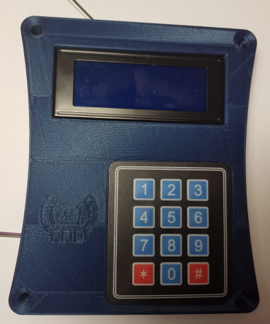
Front panel construction
Hardware construction
We will 3D print the Front panel body, then we will remove the supports and we are going to prepare it for the next steps:

Then we are going to attach all the necessary modules to complete the build:
- Lcd screen mounts to the upper 4 screws with M2.5 screws
- RC-522 sensor is mounted under the Arduino
- Membrane keypad is mounted on the front panel with the cable entering thru the small slot
- Arduino is mounted on the 4 lower screws and secures RFID module
- The whole unit will be mounted on the wall with 4 screws, one in each corner, taking care that the wires need to pass thru the wall to the back unit
Wiring
Below is attached a wiring diagram(*Sorry for not using Fritzing, not all components I needed were included)
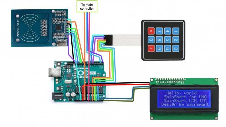
The components are connected as follows:
- LCD GND to Arduino GND
- LCD VCC to Arduino 5V
- LCD SDA to Arduino A4
- LCD SCL to Arduino A5
- KEYPAD Pin 1 to Arduino A0
- KEYPAD Pin 2 to Arduino A1
- KEYPAD Pin 3 to Arduino A2
- KEYPAD Pin 4 to Arduino A4
- KEYPAD Pin 5 to Arduino D5
- KEYPAD Pin 6 to Arduino D6
- KEYPAD Pin 7 to Arduino D7
- RC522 GND to Arduino GND
- RC522 3.3V to Arduino 3.3V
- RC522 RST to Arduino D9
- RC522 MISO to Arduino D12
- RC522 MOSI to Arduino D11
- RC522 SCK to Arduino D13
- RC522 SDA to Arduino D10
This is how it should look when assembled, you can desolder the pins from the components if you want, then solder wires directly if you would like, it will make it more resistant to shocks and also look nicer.

Back lock assembly
Hardware construction
We will 3D print the back body, then we will remove the supports and we are going to prepare it for the next steps:

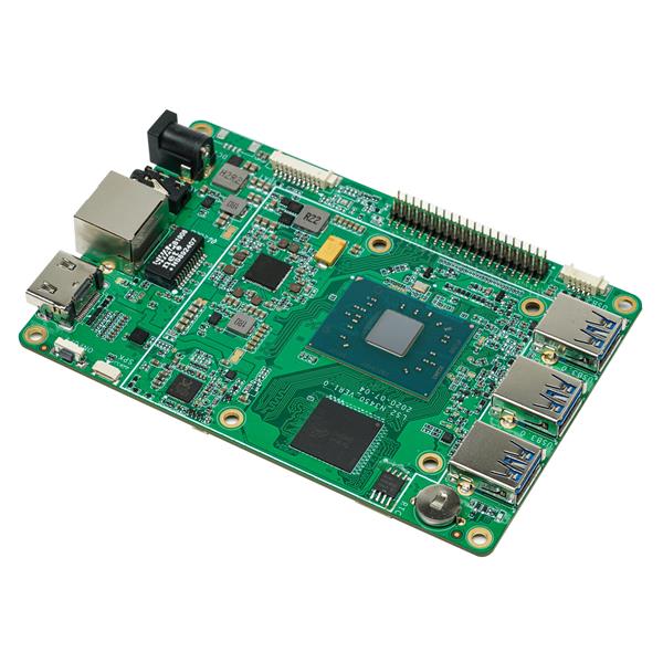
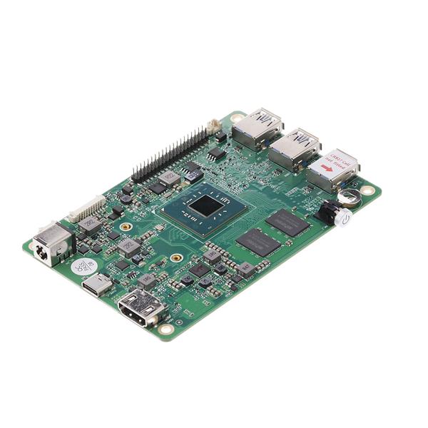
We are going to attach the necessary components next:
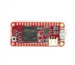
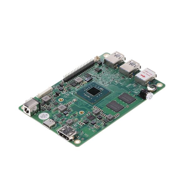
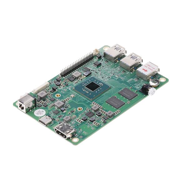
- The Giant Board sits on the bottom 4 screws with the USB port facing right, this is very important
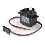
- The ServoMotor will be mounted with 2 screws, and with the output shaft facing downwards
- the Asus ZenPower batter will be mounted with the USB ports facing to the right
Wiring
The components are connected as follows:
- ServoMotor SIGNAL pin to Giant Board PWM1
- ServoMotor VCC pin to 5V rail
- ServoMotor GND pin to GND rail
- Giant Board Micro-USB port to 5V cable connected to the power bank
- Giant Board AD3 to Arduino D0
- Giant Board AD2 to Arduino D1
- Arduino VIN to 5V rail
- Arduino GND to GND rail
This is how it should look like, I would suggest making the locking bar from steel(the blue highlighted piece):

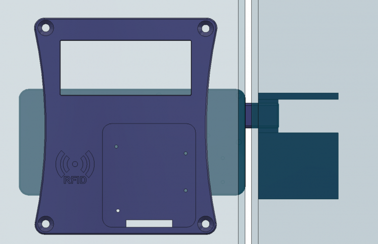
Mounting the pieces on a door
The Front Panel and the Lock Body need to communicate so they have to near each other, the front panel will be placed on the insecure parts of the door, while the lock will be placed on the secure side, they will be fixed, each with four screws, the locking bar will lock the door from moving as in the image below:
Software
Configuring the Giant Board
Installing necessary software
Firstly, we need to install a terminal emulation app, I'm using windows, so I chose Putty, you can get it at https://putty.org/. Once you have installed it, you will be greeted with this window:
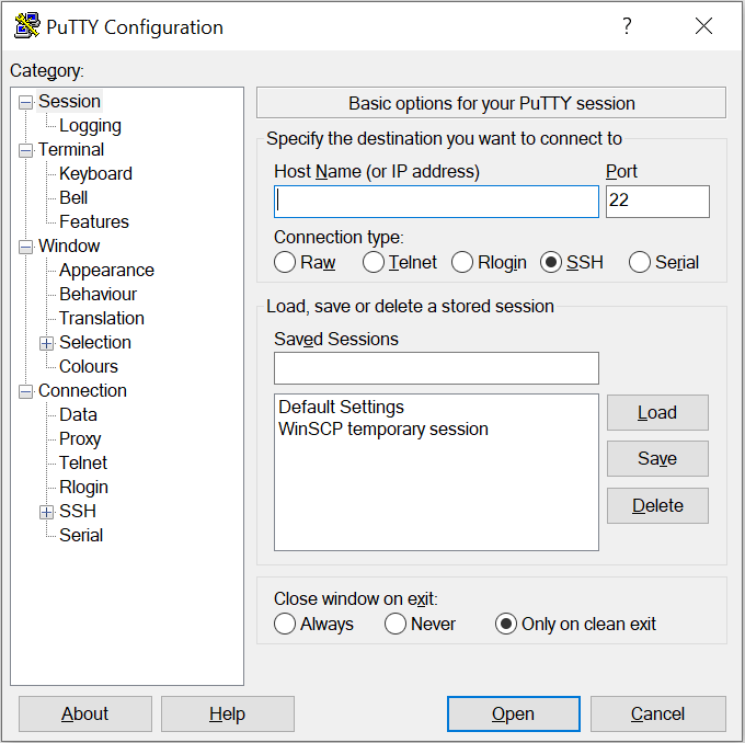
We need to select the Serial tab and enter the serial port associated with our Giant Board, if you don't know it, you can find it at Device manager, under COM ports. After we have selected it, we need to set the baud rate to 115200, then we press Open. If it doesn't work first, wait for a bit so the Giant Board has time to boot.
Configuring the controller
The default username name is debian and the default password is temppwd. Once you type that in you will be greeted by the Giant Board console!. It is recommended that you change the password with the passwd command.
First, we need to configure the network. We enter the command sudo connmanctl, it will ask for your password, enter it. You will be greeted with a prompt like this:
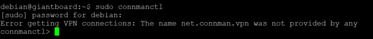
Enter the command services, it will give you a list of one device, with a name like gadget_5e70b6158b61_usb, copy it, then type connect and paste the string, you paste with right-click. you will be greeted with Connected gadget_5e70b6158b61_usb, if this is the case, then you are ready to go, if you encounter difficulties, the Giant Board documentation can be very helpful at https://groboards.com/docs/
Then we need to configure it inside Windows, go to Network and Sharing centre in the control panel, you should see something like this:
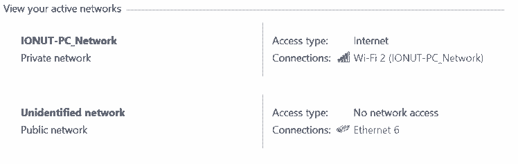
Click on the connection that has internet, in my case (Wi-Fi 2), and then go to Properties. Once you get there go to the Sharing tab and enable Sharing, this will make you select a network, select the network created by the Giant Board, in my case (Ethernet 6), once you did this, you will have Internet on your Giant Board.
The giant board uses Overlays to define hardware connectivity. You need to go enter sudo nano /boot/uboot/uEnv.txt, then you need to uncomment the line:
- enable_uboot_overlays=1
Then, you need to add to two of the overlay lines:
- GB-UART2-FLX4-AD2-AD3.dtbo
- GB-PWM1.dtbo
The first enables UART which will be used to communicate with the Arduino and the second enables PWM to control the Servo
We need to install the libraries for controlling the motor and the UART serial line and random number generation:
- pip install Adafruit-Blinka
- pip install pyserial
- pip install random2
Writing the main script
Now we are going to write the main control script for the giant board, we will discuss it in parts, but the whole code can be copied from the Attachments.First, we need to create a file named backend.py at the bin directory, we do this by using the following command:
- sudo nano bin/backend.py
This will open the text editor nano, it should look like this:
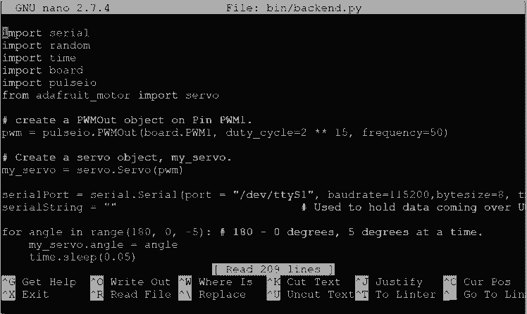
The shortcuts are in the lower part of the screen.Now we can get to writing the main script, first we add all the necessary libraries:
- import serial
- import random
- import time
- import board
- import pulseio
- from adafruit_motor import servo
Then we create the necessary objects such as the servo motor and the Serial Connection (UART):
- # create a PWMOut object on Pin PWM1.
- pwm = pulseio.PWMOut(board.PWM1, duty_cycle=2 ** 15, frequency=50)
- # Create a servo object, my_servo.
- my_servo = servo.Servo(pwm)
- serialPort = serial.Serial(port = "/dev/ttyS1", baudrate=115200,bytesize=8, timeout=2, stopbits=serial.STOPBITS_ONE) # Here you add Arduino parameters, those are default
- serialString = "" # Used to hold data coming over UART
Now we initialize the servo motor to the closed position:
- for angle in range(180, 0, -5): # 180 - 0 degrees, 5 degrees at a time.
- my_servo.angle = angle
- time.sleep(0.05)
We create the function that unlocks the door so we can call it later if the correct credentials are supplied:
- def unlock():
- for angle in range(0, 180, 5): # 0 - 180 degrees, 5 degrees at a time.
- my_servo.angle = angle
- time.sleep(0.05)
- time.sleep(2)
- for angle in range(180, 0, -5): # 0 - 180 degrees, 5 degrees at a time.
- my_servo.angle = angle
- time.sleep(0.05)
If your motor is backward change 0 to 180, 180 to 0, 5 to -5, and -5 to 5 in the parameters of range.
Now we add the function that defines ourselves (the user):
- # this is the secure info of user "me"
- def me(type, token):
- # Here you put the passcode
- if (type == 1):
- return "111111"
- # Here you put the RFID tag info
- if (type == 2):
- return "66949828"
- if (type == 3):
- d1 = token[0]
- d2 = token[1]
- d3 = token[2]
- d4 = token[3]
- d5 = token[4]
- d6 = token[5]
- d7 = token[6]
- d8 = token[7]
- # here you write your 2FA rule
- result = ''
- result += str((d1 + 1) % 10)
- result += str((d2 + 2) % 10)
- result += str((d3 + 3) % 10)
- result += str((d4 + 4) % 10)
- result += str((d5 + 5) % 10)
- result += str((d6 + 6) % 10)
- result += str((d7 + 7) % 10)
- result += str((d8 + 8) % 10)
- return result
In the first 'if', we add our passcode, in the second, our RFID tag and in the third our 2FA rule, in this case, I take every digit and add 1 to the first digit 2 to the second, etc, taking only the last digit so we get an array with an identical number of digits.
The rest of the script is just validation:
- def genrand():
- # here we generate a random token
- s1 = random.randint(0, 10)
- s2 = random.randint(0, 10)
- s3 = random.randint(0, 10)
- s4 = random.randint(0, 10)
- s5 = random.randint(0, 10)
- s6 = random.randint(0, 10)
- s7 = random.randint(0, 10)
- s8 = random.randint(0, 10)
- return [s1,s2,s3,s4,s5,s6,s7,s8], str(s1)+str(s2)+str(s3)+str(s4)+str(s5)+str(s6)+str(s7)+str(s8)
- while(1):
- # Wait until there is data waiting in the serial buffer
- if(serialPort.in_waiting > 0):
- # Read data out of the buffer until a carraige return / new line is found
- serialString = serialPort.readline()
- # Print the contents of the serial data
- comm = serialString.decode('Ascii')
- comm = comm.strip()
- # Separate string into 2 parts delimited by '|'
- str1, str2 = comm.split('|')
- # Verify if the connection started
- if (str1 == 'COMM' and str2 == 'START'):
- print("Connection succesfull!")
- if (str1 == 'PASS'):
- print('PASS ==> ' + str2)
- if (me(1, '') == str2):
- print ("PASS OK")
- serialPort.write(b"MODE|SQRFIDn")
- exit = False
- while exit == False:
- if (serialPort.in_waiting > 0):
- exit = True
- # Read data out of the buffer until a carraige return / new line is found
- serialString = serialPort.readline()
- # Print the contents of the serial data
- comm = serialString.decode('Ascii')
- comm = comm.strip()
- # Separate string into 2 parts delimited by '|'
- str1, str2 = comm.split('|')
- if (str1 == 'RFID'):
- if (me(2, '') == str2):
- print('RFID OK')
- serialPort.write(b"MODE|SQ2FAn")
- exit1 = False
- while exit1 == False:
- if (serialPort.in_waiting > 0):
- exit1 = True
- # Read data out of the buffer until a carraige return / new line is found
- serialString = serialPort.readline()
- # Print the contents of the serial data
- comm = serialString.decode('Ascii')
- comm = comm.strip()
- # Separate string into 2 parts delimited by '|'
- str1, str2 = comm.split('|')
- if (str1 == 'MODE'):
- token, tokenstr = genrand()
- tokenstr = tokenstr[0:8]
- serialPort.write(bytes((tokenstr + 'n').encode()))
- exit2 = False
- while exit2 == False:
- if (serialPort.in_waiting > 0):
- exit2 = True
- # Read data out of the buffer until a carraige return / new line is found
- serialString = serialPort.readline()
- # Print the contents of the serial data
- comm = serialString.decode('Ascii')
- comm = comm.strip()
- # Separate string into 2 parts delimited by '|'
- str1, str2 = comm.split('|')
- if (str2 == me(3,token)):
- print("2FA OK")
- serialPort.write(b"ACC|GRANTn")
- unlock () # unlock
- else:
- print("2FA FALSE")
- serialPort.write(b"ACC|INTRn")
- else:
- print("RFID FALSE")
- serialPort.write(b"ACC|INTRn")
- else:
- print("PASS FALSE")
- serialPort.write(b"ACC|INTRn")
- if (str1 == 'RFID'):
- print('RFID ==> ' + str2)
- if (me(2, '') == str2):
- print("RFID OK")
- serialPort.write(b"MODE|SQPASSn")
- exit = False
- while exit == False:
- if (serialPort.in_waiting > 0):
- exit = True
- # Read data out of the buffer until a carraige return / new line is found
- serialString = serialPort.readline()
- # Print the contents of the serial data
- comm = serialString.decode('Ascii')
- comm = comm.strip()
- # Separate string into 2 parts delimited by '|'
- str1, str2 = comm.split('|')
- if (str1 == 'PASS'):
- if (me(1, '') == str2):
- print('PASS OK')
- serialPort.write(b"MODE|SQ2FAn")
- exit1 = False
- while exit1 == False:
- if (serialPort.in_waiting > 0):
- exit1 = True
- # Read data out of the buffer until a carraige return / new line is found
- serialString = serialPort.readline()
- # Print the contents of the serial data
- comm = serialString.decode('Ascii')
- comm = comm.strip()
- # Separate string into 2 parts delimited by '|'
- str1, str2 = comm.split('|')
- if (str1 == 'MODE'):
- token, tokenstr = genrand()
- tokenstr = tokenstr[0:8]
- serialPort.write(bytes((tokenstr + 'n').encode()))
- exit2 = False
- while exit2 == False:
- if (serialPort.in_waiting > 0):
- exit2 = True
- # Read data out of the buffer until a carraige return / new line is found
- serialString = serialPort.readline()
- # Print the contents of the serial data
- comm = serialString.decode('Ascii')
- comm = comm.strip()
- # Separate string into 2 parts delimited by '|'
- str1, str2 = comm.split('|')
- if (str2 == me(3, token)):
- print("2FA OK")
- serialPort.write(b"ACC|GRANTn")
- unlock() # unlock
- else:
- print("2FA FALSE")
- serialPort.write(b"ACC|INTRn")
- else:
- print("PASS FALSE")
- serialPort.write(b"ACC|INTRn")
- else:
- print("RFID FALSE")
- serialPort.write(b"ACC|INTRn")
After the script is written we can make it start at the boot of the Giant Board, to do this we need to add a new crontab:
- sudo crontab -e
Then we need to specify our script, we add this line to the bottom of the file, after all the #'s:
- @reboot python /bin/your_script.py &
Then we can reboot our board with sudo reboot.
Configuring the Arduino
Installing necessary software
We need the Arduino IDE to send programs to our Arduino, we can get it at https://www.arduino.cc/en/Main/Software
After we have downloaded it we will be greeted with a page that looks like this: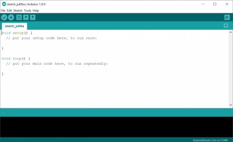
Now we are ready to add the necessary code so our Arduino becomes a frontend, like our python script, we first add the necessary libraries:
- #include <Wire.h>
- #include <LiquidCrystal_I2C.h>
- #include <SPI.h>
- #include <MFRC522.h>
Then we add variables and define some instances for the RFID reader and the LCD screen:
- // Variables for the main program
- const int tokensize = 8;
- int mode = 1; // 1 = can read rfid + passcode 2 = rfid 3 = passcode 4 = 2FA
- String command;
- String token;
- // RFID reader pins and variables
- #define SS_PIN 10
- #define RST_PIN 9
- MFRC522 rfid(SS_PIN, RST_PIN); // Instance of the class
- MFRC522::MIFARE_Key key;
- byte uid[4];
- //Keypad characters
- char digits[10];
- int keychar, cont;
- int keypressed = 0;
- char characters[] = {' ','3','6','9','#','2','5','8','0','1','4','7','*'}; // characters on the keypad
- //LCD screen I2C address (0x3F)
- LiquidCrystal_I2C lcd(0x3F, 20, 4);
Now we enter the setup part of the script, this tells the microcontroller, in this case, the Atmega328p what to do when first starting up, here we set up pins and start the RFID reader, the UART interface and the LCD interface:
- void setup() {
- // setting up pins for the 3 X 4 matrix keypad
- pinMode(5, OUTPUT);
- pinMode(6, OUTPUT);
- pinMode(7, OUTPUT);
- pinMode(A0, INPUT_PULLUP);
- pinMode(A1, INPUT_PULLUP);
- pinMode(A2, INPUT_PULLUP);
- pinMode(A3, INPUT_PULLUP);
- // starting a serial connection for monitoring
- Serial.begin(115200);
- //Serial.println("AS-Frontend-v-1.1");
- Serial.println("COMM|START");
- // starting SPI bus for RFID reader
- SPI.begin(); // Init SPI bus
- rfid.PCD_Init(); // Init MFRC522
- for (byte i = 0; i < 6; i++) {
- key.keyByte[i] = 0xFF;
- }
- // printing info on the lcd
- lcd.begin();
- lcd.print(" Access system");
- lcd.print(" Rev 1.1");
- delay(100);
- lcdstd();
- // it needs to read RFID + Passcodes
- mode = 1;
- }
The Arduino communicates with the Giant Board with short messages like COMM|START for starting the bus.
We now get into the different functions that make all of this to work
We first have the function that reads from the keypad, I know that there are off the shelf alternatives from Adafruit but those use the digital pins, mine also uses the analog pins so we can use more stuff with our little microcontroller, I tried to comment the code as much as I can but if anyone would like to know something you can leave it in the comments down below.
- int keypad() {
- float a = 0, b = 0, c = 0, d = 0, thresh = 100.0;
- // here we iterate thru the rows and the columns to check whether there is any key pressed
- digitalWrite(5, LOW);
- digitalWrite(6, HIGH);
- digitalWrite(7, HIGH);
- a = analogRead(A0);
- b = analogRead(A1);
- c = analogRead(A2);
- d = analogRead(A3);
- if (a < thresh) {
- return 1;
- }
- if (b < thresh) {
- return 2;
- }
- if (c < thresh) {
- return 3;
- }
- if (d < thresh) {
- return 4;
- }
- digitalWrite(5, HIGH);
- digitalWrite(6, LOW);
- digitalWrite(7, HIGH);
- a = analogRead(A0);
- b = analogRead(A1);
- c = analogRead(A2);
- d = analogRead(A3);
- if (a < thresh) {
- return 5;
- }
- if (b < thresh) {
- return 6;
- }
- if (c < thresh) {
- return 7;
- }
- if (d < thresh) {
- return 8;
- }
- digitalWrite(5, HIGH);
- digitalWrite(6, HIGH);
- digitalWrite(7, LOW);
- a = analogRead(A0);
- b = analogRead(A1);
- c = analogRead(A2);
- d = analogRead(A3);
- if (a < thresh) {
- return 9;
- }
- if (b < thresh) {
- return 10;
- }
- if (c < thresh) {
- return 11;
- }
- if (d < thresh) {
- return 12;
- }
- return 0;
- }
Then we have some code to change the message on the display:
- void lcdstd()
- {
- lcd.begin();
- delay(100);
- lcd.print(" Scan RFID tag ------ Type passcode");
- }
- void lcdauth()
- {
- lcd.begin();
- lcd.backlight();
- delay(100);
- lcd.print(" Access Granted");
- delay(2000);
- lcdstd();
- }
- void lcdnauth()
- {
- lcd.begin();
- lcd.backlight();
- delay(100);
- lcd.print(" Access Restricted Try again");
- delay(2000);
- lcdstd();
- }
Now we need to read from the RC522 reader so we need to get the data from the SPI bus and format it so it can be read by our program using this script, if anyone is wondering, we use only the UID of the tag:
- bool card_reader()
- {
- bool card = false;
- if (rfid.PICC_IsNewCardPresent() && rfid.PICC_ReadCardSerial())
- {
- for (byte i = 0; i < 4; i++)
- {
- uid[i] = rfid.uid.uidByte[i];
- card = true;
- }
- }
- rfid.PICC_HaltA();
- rfid.PCD_StopCrypto1();
- return card;
- }
Finally, we get to the main loop, which just verifies if any code or any tag is provided to the reader and if so it sends them to the Giant Board for verification:
- void loop()
- {
- if(card_reader() && mode != 2 && mode != 4)
- {
- Serial.print("RFID|");
- for (byte i = 0; i < 4; i++)
- {
- Serial.print(uid[i]);
- }
- //Serial.println("|");
- lcd.setCursor(7,2);
- lcd.print("******");
- lcdstd();
- mode = 0;
- }
- keychar = keypad();
- if(keychar!=keypressed && mode != 3 )
- {
- keypressed = keychar;
- lcd.setCursor(7,2);
- if(mode==4){
- lcd.setCursor(6,2);
- }
- //lcd.print(characters[keychar]);
- cont = true;
- int i=0;
- int m = 5;
- if(mode == 4){
- m = tokensize - 1;
- }
- while(i <= m) // stops after 6 digits
- {
- delay(50);
- keychar=keypad();
- if(keychar == 0)
- {
- cont = true;
- }
- if(keychar != 0 && cont == true)
- {
- //lcd.print(characters[keychar]); //uncomment this if you want the passcode to be visible when written
- digits[i]=characters[keychar];
- i++;
- lcd.print('*');
- cont = false;
- }
- }
- if(mode != 4){
- Serial.print("PASS|");
- }
- else{
- Serial.print("2FAS|");
- }
- for(int i=0;i<=m;i++){
- Serial.print(digits[i]);
- }
- //Serial.println("|");
- lcdstd();
- keypressed=0;
- mode = 0;
- }
- while(Serial.available() > 0)
- {
- command = Serial.readString();
- if(command == "MODE|SQPASSn")
- {
- //Serial.println("MODE|PASS");
- mode = 2;
- lcd.setCursor(3,1);
- lcd.print("Enter Passcode ");
- lcd.setCursor(3,0);
- lcd.print(" ");
- }
- if(command == "MODE|SQRFIDn")
- {
- //Serial.println("MODE|RFID");
- mode = 3;
- lcd.setCursor(3,1);
- lcd.print("Scan RFID tag ");
- lcd.setCursor(3,0);
- lcd.print(" ");
- }
- if(command == "MODE|SQ2FAn")
- {
- Serial.println("MODE|2FAPASS");
- mode = 4;
- while(Serial.available() == 0){}
- token = Serial.readString();
- token[tokensize]=' ';
- lcd.setCursor(3,0);
- lcd.print("Enter 2FA token");
- lcd.setCursor(3,1);
- lcd.print(" ");
- lcd.setCursor(6,1);
- lcd.print(token);
- lcd.setCursor(6,2);
- lcd.print("--------");
- }
- if(command == "ACC|GRANTn")
- {
- Serial.println("ACCESS|OK");
- lcdauth();
- }
- if(command == "ACC|INTRn")
- {
- Serial.println("ACCESS|NO");
- lcdnauth();
- }
- }
- }
And now, we have officially finished the hardware and software, we can talk about the cons and the post to such a system:
Pros and Cons
Pros:
- It doesn't use any external device(RFID can be removed), unlike other systems that depend on your phone to verify, those systems prove useless if the said device runs out of battery, which in our world could easily happen.
- It doesn't rely on other services to process data, like AWS or Google Cloud, or any other IoT service, this makes it more secure and independent of said services.
- It doesn't have the flaw that many systems have, which is that the part that opens the door is on the insecure side, thus making it practically useless, requiring basic skills to open, these flaws are easily exploitable by using an external battery to open the solenoid or the motor
- The power bank acts as a UPS "Uninterruptable Power Supply", that makes it work even if the power is down in your respective place.
- It is cheap to build and I think it looks relatively nice
- There is room for integration with more of these systems, to have a centralized database on your home server that keeps all the events.
Cons:
- Takes getting used to the 2FA code
- 3D printed parts are not extremely durable, this can be improved by milling them with a CNC out of aluminum.
- The lock body with the servo is vulnerable to brute force attacks, this can be easily solved with an external solenoid, I just couldn't find one near where I live.
- Is not waterproof.
Final prototype
This is how it looks when the correct codes and RFID key are entered:
This is how it looks when an incorrect RFID tag is placed:
That is it, I hope you like it and maybe it inspired you to build something like this, if you have any idea, share it with us in the comments below!
Schematics, diagrams and documents
CAD, enclosures and custom parts
Code
Credits
Related products


Leave your feedback...