
Project info
Items used in this project

Story
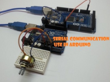
In this video I’m going to cover the basic functions of Serial communication, and end with a demonstration of connecting Arduino uno to Arduino mega via serial.
The idea for the video came from seeing the same questions asked, and the confusing and contradicting answers people give to them. So I hope that by the end I will cover thus basics and make it as clear as possible. Let start with the first step, the Serial.begin(). This is the function that start the Serial service and the number between the brackets is the baudrate.
Why it’s so important – because this is the speed the serial will communicate at – and trying to communicate in other baudrate – will result in either blank or gibberish output. The next thing I want to cover is the the Serial.print vs Serial.write and the way the data is transferred in both methods. Side note – whatever I say about print() goes for println() just with a “rn” added in the end to get a line break in the output. Print function will take any value you feed it and change it to its string representation, which is what the IDE monitor tool is expecting. Here is a link to the page in arduino showing how things get converted
https://www.arduino.cc/reference/en/language/functions/communication/serial/print/
Now – on the other hand the write function of 66 produced a“B” on the screen – and the reason for that is, that unlike the print function the write function send the BYTE value as is, without conversation.
And since the Serial monitor is expecting a char to arrive, and there for takes the byte value of 66 and turn it to its char – which is in our case “B”. take a look at any ascii table. I’m sure this is still a bit if not a lot confusing especially if you never dealt with data conversions before. on top of that you only see the output and not the actual data.
So now, let’s reverse the roles, and I will be sending data from the serial monitor to the Arduino, and parsing it out. will take this example and run it.
void setup() {
 Serial.begin(115200);
 Serial.print("Please enter data");
 Serial.print("n");
}
void loop() {
   while (Serial.available()) {
     byte rec = Serial.read();
     Serial.print(rec);
    // Serial.print(" - ");
    // Serial.print((char) rec);
     Serial.print("n");
   }
}
When I send 165 from the serial monitor I get a strange 4 byte result. Now remember I told you that Serial.print turns everything into strings, so does the monitor tool, so we get 3 characters one for each of the digits. Now since we read and display a byte – we see their asci value.
Now in order to explain the 4th byte I have to take a Small detour and go over the drop down that is responsible of adding (or not) an extra characters at the end of the message you send. In our case its set to new line n which it asci value is 10. Take a look at the bottom right of your IDE serial monitor
Now uncomment the extra 2 lines, Note – each value is corresponding to a digit, if cast as a char.
If you never done data types conversations in the past, I got a series of video :
Some system will pass numeric data as string and not as its value. And Arduino have given us some tools to convert it during the read process. The 2 are parseInt() & parseFloat() both will take a string representation of a value and turn it into the actual value in a specific data type.
In this example we enter a numeric value in the serial monitor and use parseint() to read and convert it to integer. We then display the value entered times 2 back.
void setup() {
 Serial.begin(115200);
 Serial.print("Please enter data");
 Serial.print("n");
}
void loop() {
   if (Serial.available()) {
     int value = Serial.parseInt();
     Serial.print("Number entered X2: ");
     Serial.print(value*2);
     Serial.print("n");
   }
}
Now lets take it all and put it into use
In order for 2 systems to talk to each other, they need to have some forms of communications roles.
The first one is to know that we are reading a start of a message, there for you will often see a starting characters that will mark just that.
Then the receiving end needs to know when to stop reading, in most cases this can be achieved by adding an end character.
The other option is to let the receiver know how many bytes it needs to read. So in some cases the first value after the starting characters– will be the length of the message.
Or decide in advance on a fixed message size like I do in my example.
Since errors can and will happen One more thing that can be added in order to keep data integrity is a checksum – a way to make sure we got the data correctly by preforming math on received data.
I will say in advance that there are many ways to do what I did in the following example.
In this example will be sending The uno analog read value of pin A0 to the serial every 250 millis.
The data message will have a fixed bytes format with 2 opening bytes 253, 255, followed by the lower and upper byte of the read value integer, and the checksum is added last.
void setup() {
 Serial.begin(9600);
}
void loop() {
 int analogVal = analogRead(A0);
 byte checksum = 0;
 checksum += (byte) analogVal;
 checksum += (byte) (analogVal >> 8);
 Serial.write(253); // start
 Serial.write(255); // start
 Serial.write(analogVal); // lower byte
 Serial.write(analogVal >> 8); // upper byte
 Serial.write(checksum); //checksum
 delay(250);
}
I connected the uno serial TX is to the Serial1 RX on the mega, the reason I used serial1 is to allow myself the use the Serial to output the data to the serial monitor. And remember to share grounds.
on the mega we wait for serial1 data to be available,
we read the data into a buffer and keep an index of the buffer position.
if message was not started and it at least 2 bytes long we look for 2 starting bytes 253, 255 in a row – to mark the start of the message.
Once found we reset the buffer index to zero and set the message start flag to true.
we then read the 3 bytes of the known message size.
compare the data to the checksum
and if that matches we rebuild he integer from its 2 bytes parts and output it via the serial monitor
last we reset the message start flag to false – to start looking for the next message.
This can be done with even bigger datatypes like long. And with more than one parameter at a time – as long as you keep the right format. I hope this covered some of your basic questions on how to use serial
Schematics, diagrams and documents
Code
Credits
Related products


Leave your feedback...