Rp2040 Based Pi-day Bling
About the project
RP2040-based bling that changes its LED color when it detects one of three keywords: "Pi", "3.14", or "Irrational"
Project info
Difficulty: Moderate
Platforms: Adafruit, Raspberry Pi, Edge Impulse
Estimated time: 1 hour
License: MIT license (MIT)
Items used in this project
Hardware components
Story
Happy Pi-Day! This project describes a bling designed around the RP2040 microcontroller. In the spirit of celebrating Pi-Day, it is designed to capable of detecting three words namely: Pi, 3.14, and Irrational. When it detects one of these keywords, the RGB LEDs on the bling change their color.
Pi Day Bling -Front View
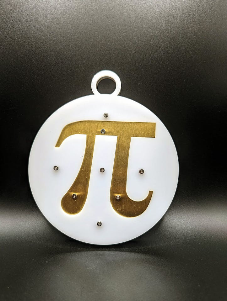
Pi Day Bling -Front View
ComponentsThe bling is designed around the RP2040 microcontroller. The following image shows the components of the bling.
Bling - Back side
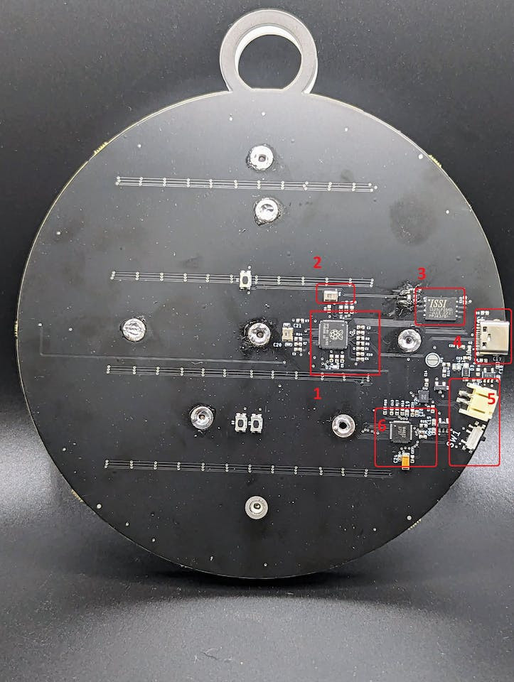
Bling - Back side
The components of the bling on the back side (in numerical order) include:
- RP2040 microcontroller
- Goertek SD18OB261-060 PDM microphone
- Flash memory
- USB-C port
- Li-Po battery port + charger
- IS31FL3737 LED driver
The components on the front side of the bling include 12 WS2812B individually addressable RGB LEDs and 48 RGB LEDs.
Bling - Front Side
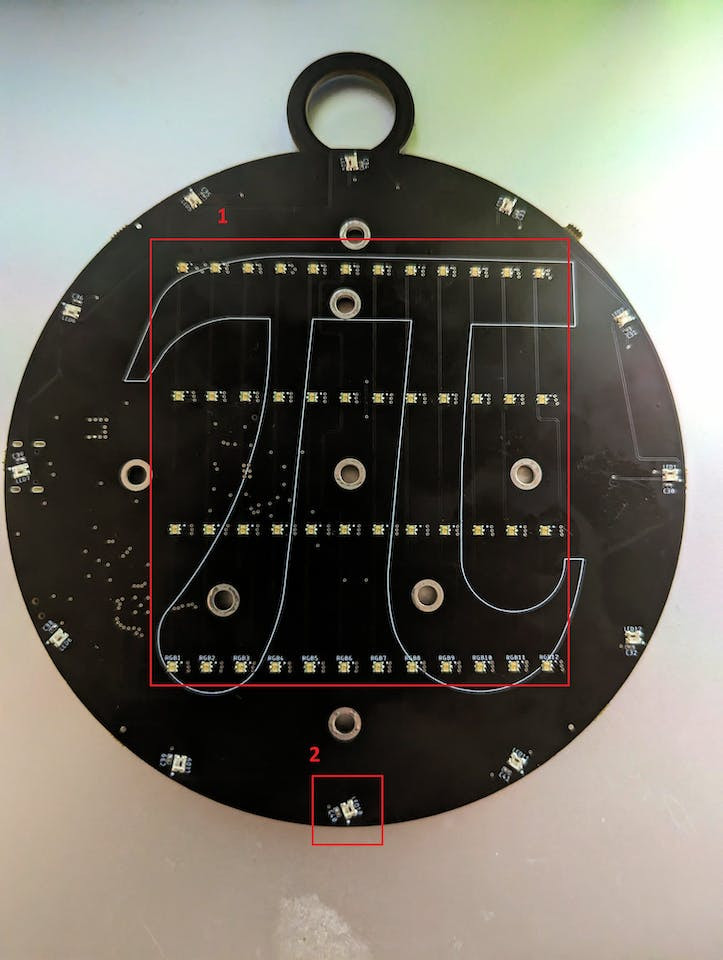
Bling - Front Side
The board was designed with Autodesk Eagle and assembled using JLCPCB. The bling's maximum dimensions are 144.9 mm * 165.9 mm.
Edge ImpulseThe PDM microphone in the bling is used to detect three keywords associated with Pi namely: Pi, 3.14, and Irrational. The audio samples required for the classification was collected using a browser and a model was built using Edge Impulse. The Edge Pulse model is available from here.
Here is a demo of the model deployed on the RP2040 microcontroller:
Edge Impulse model deployed on the RP2040 microcontrollerProgrammingThe bling was programmed and tested in two ways:
- Using Arduino IDE
- Using Raspberry Pi Pico C/C++ SDK
Edge Impulse enables testing the code right away since it comes with code samples to test on different platforms. The Arduino code is made available below. Since the RP2040 is a dual core microcontroller, the code is structured as follows:
- The first core collects audio from the PDM microphone and runs the inference using the Edge Impulse model.
bool m = microphone_inference_record();
if (!m) {
ei_printf("ERR: Failed to record audio...n");
return;
}
ei_printf("Recording donen");
signal_t signal;
signal.total_length = EI_CLASSIFIER_RAW_SAMPLE_COUNT;
signal.get_data = µphone_audio_signal_get_data;
ei_impulse_result_t result = { 0 };
EI_IMPULSE_ERROR r = run_classifier(&signal, &result, debug_nn);
if (r != EI_IMPULSE_OK) {
ei_printf("ERR: Failed to run classifier (%d)n", r);
return;
}If a keyword is detected with at least 90% confidence, we need to change the color. The first core of the microcontroller pushes the color to a queue.
void print_inference_result(ei_impulse_result_t result) {

    // Print how long it took to perform inference
    ei_printf("Timing: DSP %d ms, inference %d ms, anomaly %d msrn",
            result.timing.dsp,
            result.timing.classification,
            result.timing.anomaly);

    ei_printf("Predictions:rn");
    for (uint16_t i = 0; i < EI_CLASSIFIER_LABEL_COUNT; i++) {
        ei_printf("  %s: ", ei_classifier_inferencing_categories[i]);
        ei_printf("%.5frn", result.classification[i].value);
        if(i != 3 && result.classification[i].value > 0.90){
           rp2040.fifo.push(colors[i]);
        }
    }

}
On the other core, we change the color if new data is available in the queue by using the pop() method.
void loop1(){
    if(rp2040.fifo.available()){
      color = rp2040.fifo.pop();
    }
    colorWipe(color, 50); // Red
    colorWipe(strip.Color(0, 0, 0), 25); // Green
}The Pi symbol was cut in brass while the background is cut is translucent white acrylic. They are assembled using M2.5 screws.
Assembled Bling
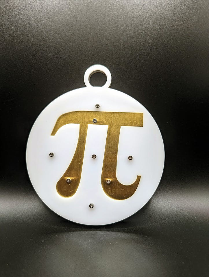
Assembled Bling
DemoThe following video shows the bling in action. It changes color every time a keyword is detected!
Pi Day Bling VideoNext StepsThe technical debt on this project include:
- IS31FL3737 drivers: Currently, the bling was built using the Neopixel LEDs. There are 48 RGB LEDs. The drivers for this chipset needs to be completed.
- Power Profiling: The power consumption of the bling needs to be profiled to determine the battery size.
- Fine tuning Pico C SDK code performance: Currently, the Arduino IDE based deployment can deploy all three keywords correctly while the C SDK based code sample can only detect 2/3 keywords. This needs further investigation.



Leave your feedback...