
Rotary Encoder Using Arduino

About the project
The rotary encoder supports the user to interact with the system and in this project, we interface it with Arduino.
Project info
Difficulty: Moderate
Platforms: Arduino
Estimated time: 1 day
License: GNU General Public License, version 3 or later (GPL3+)
Items used in this project
Hardware components


Story
About the Project:
A Rotary Encoder basically is an electromechanical transducer that converts mechanical movements into electronic pulses. It contains a knob which when moves step by step and generates a sequence of pulse trains with a predefined width
The various types of encoders are rated depends upon the Output signal and sensing technology. The Encoder utilized here is an Incremental type of Encoder.
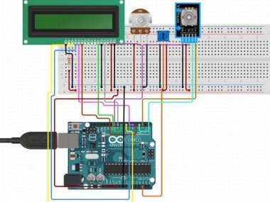
Rotary Encoder with Arduino
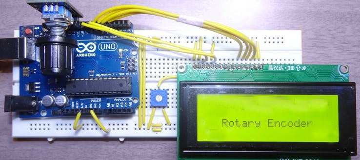
Once the hardware is ready, you need to just upload the code to the Arduino board and power up the Arduino Board. Power it with the help of the USB cable or a 12V adapter. When it gets powered the LCD should display the message and then get blank. Then rotate the rotary encoder and you can see the value start incremented or decremented depends on the direction you rotate. You can see below image.
And when the button is pressed, the second line will display that the button is pressed.
Build such IoT Projects using Arduino with the help of the Internet of Things Course Training
Code
Credits
Related products


Leave your feedback...