
Rgb Led Mask Controlled With App (arduino)

Made by thor-christian-stenbaek / Lights / Wearables
About the project
With coronavirus still active in all of the world everyone is still expected to wear masks everywhere. That's fine! But why do the masks have to be so boring? Let's make them fun. In this project I'll walk you through how you can make your own cyperpunk-ish mask.
Project info
Difficulty: Moderate
Estimated time: 6 hours
License: GNU General Public License, version 3 or later (GPL3+)
Items used in this project
Hardware components

Story
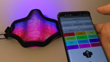
This is how the app and the mask looks. If you're unsure whether or not you'd like to make this project take a look at the video and make up your mind.
Introduction:
This project is done in 5 parts.
- Hardware
- Software for the arduino
- Building the app
- Getting the light right
- Building the mask
1. Hardware
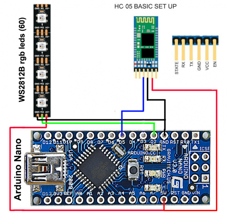
The hardware is pretty easily setup. Just follow the picture below. If you're worried about breaking the LEDs I suggest you put a small resistor (330 ohm) between D2 and the Din onWS2812B.
2. Software for the arduino.
If you're not interested in how the code works I've also attached the code for you to download and you can skip right to that.
2.1) Explaining the communicating with the bluetooth device.
First include the software serial library in your code as we'll be using that to communicate with our bluetooth device.
- #include <SoftwareSerial.h>
After that you should identify what pins should be your RX and TX. We're only using the RX in this project, but both should be present in the code. (RX is for receiving data. TX is for tranmitting data.) The "mySerial" part is the name of our new software serial ports, you can change the name if you'd like, but I'll refer to it as 'mySerial' from here.
- SoftwareSerial mySerial(5, 4); // RX, TX
In the void setup() you should write 'mySerial.begin(9600)'. This enables the software serial and allows us to parse 9600 bytes, which works fine for communicating with the HC05 bluetooth device.
- void setup()
- {
- // set the data rate for the SoftwareSerial port
- mySerial.begin(9600);
- //Begins the software serial "mySerial"
- }
In the void loop you should write the following statements. mySerial.available() checks whether there is any bytes from the bluetooth device coming into our arduino.
'state' is a variable and in the code we're using it to save whatever byte we get from reading what comes from the bluetooth device. We read what comes in with 'mySerial.read();"
- void loop() // run over and over
- {
- //This checks the first incoming byte from the bluetooth device.
- if (mySerial.available())
- state = mySerial.read();
- }
Once we've saved the variable we can use it to check whether a specific byte is coming into our arduino and then we can excecute some commands. This is what the entire app-arduino communication is built on.
- if (state==33 ){
- //Do something
- }
Unfortunately we cannot check whether this is correct or not before we've made the app that connects to the bluetooth device.
2.2) Explaining the software for the LEDs
The software for the LEDs also needs a library. We're using Adafruit's NeoPixel.
- #include <Adafruit_NeoPixel.h>
Before anything else you should define what pin you plan to use for the DIN in your led strip. We're using 2. You should also define the number of LEDs in your strip. In our case we're using 60.
- #define PIN 2 // input pin Neopixel is attached to
- #define NUMPIXELS 60 // number of neopixels in strip
- Adafruit_NeoPixel pixels = Adafruit_NeoPixel(NUMPIXELS, PIN, NEO_GRB + NEO_KHZ800);
In the setup, you must write pixels.begin or the LEDs won't work.
- void setup()
- {
- pixels.begin();
- //Makes sure the neo pixels are working
- }
Using the RGB LEDs is pretty simple. In the loop you will have these two lines of code in quite a few places. the 'pixels.setPixelColor' sets the color of the pixels. The NUMBER is whatever led you want to light up. If you type '35' it will light up LED '35'. Choosing the color of the LED is done with 'pixels.Color(a,b,c)'. These are RGB colors and go from 0-255. a is red. b is green. c is blue. You can mix and match colors however you like. If you want to get the red color you should write 'pixels.setPixelColor(NUMBER,pixels.Color(255,0,0)); and you'll turn one LED red somewhere.
pixels.show() is what actually changes the LEDs in the hardware. Once you've set a color, you must also write 'pixels.show()' otherwise there'll be no change at all.
- pixels.setPixelColor(NUMBER, pixels.Color(redColor, greenColor, blueColor));
- pixels.show();
2.3) The whole code
Now that you've unterstood some of the basic context, let's look at the entire code together. I've put some useful comments for you in the code itself.
- #include <SoftwareSerial.h>
- #include <Adafruit_NeoPixel.h>
- #define PIN 2 // input pin Neopixel is attached to
- #define NUMPIXELS 60 // number of neopixels in strip
- Adafruit_NeoPixel pixels = Adafruit_NeoPixel(NUMPIXELS, PIN, NEO_GRB + NEO_KHZ800);
- int delayval = 100; // timing delay in milliseconds
- int redColor = 0; //redcolor for the leds sliding downwards
- int greenColor = 0; //greencolor for the leds sliding downwards
- int blueColor = 0; //bluecolor for the leds sliding downwards
- int redColor2 = 0; //redcolor for the leds sliding upwards
- int greenColor2 = 0; //greencolor for the leds sliding upwards
- int blueColor2 = 0; //bluecolor for the leds sliding upwards
- int x=60; //Determing the posittion of the LED sliding downwards
- int i=0; //Determing the posittion of the LED sliding upwards
- int updown; //For changing whether you want to change the color for upwards or downwards.
- SoftwareSerial mySerial(5, 4); // RX, TX
- int state;
- int ModeChange;
- int Colorcode;
- int identifier;
- //This is a list for creating colors.
- int ColorList[13][3]= {{255,0,0}, //red
- {255, 127,0}, //orange
- {255,255,0}, //yellow
- {127,255,0}, //green yellow
- {0,255,0}, //Green
- {0,255,127}, //Green Cyan
- {0,255,255}, //Cyan
- {0,127,255}, //Blue Cyan
- {0,0,255}, //Blue
- {127,0,255}, //Blue Magenta
- {255,0,255}, //Magenta
- {255,0,127}, //Red Magenta
- {0,0,0}}; //OFF
- void setup()
- {
- // Open serial communications and wait for port to open:
- Serial.begin(9600);
- while (!Serial) {
- ; // wait for serial port to connect. Needed for Native USB only
- }
- pixels.begin();
- //Makes sure the neo pixels are working
- // set the data rate for the SoftwareSerial port
- mySerial.begin(9600);
- //Begins the software serial "mySerial"
- }
- void mode(){
- //This part is for changing whatever mode the led mask is in.
- //ModeChange <5 is just for the regular sliding LEDs down. There are other if statements under this to give the mask more commands.
- if (ModeChange<5){
- // pixels.Color takes RGB values, from 0,0,0 up to 255,255,255
- pixels.setPixelColor(i, pixels.Color(redColor, greenColor, blueColor));
- i=i+1; //decides which led to light up
- //ModeChange 4 is just for the regular sliding LEDs down, however every LED will now change color.
- if (ModeChange==4){//Sliding dots
- setColor();
- }
- //This is for the regular sliding LEDs except now they also slide upwards. These take their own color too.
- if (ModeChange==3){ //Double Sliding colors
- x=x-1; //decides which led to light up
- pixels.setPixelColor(x, pixels.Color(redColor2, greenColor2, blueColor2 ));
- }
- // This sends the updated pixel color to the hardware.
- pixels.show();
- //This resets the the variable that controls the LEDs that slide downwards. You might need to change it if you have less than 60.
- if (x==0){
- x=60;
- };
- //This resets the the variable that controls the LEDs that slide upwards. You might need to change it if you have less than 60.
- if (i==60){
- i=0;
- setColor();
- };
- }
- //This changes the mode of the mask so you're able too change every LED individually in the app.
- else if (ModeChange==5){
- pixels.setPixelColor(identifier, pixels.Color(redColor, greenColor, blueColor));
- pixels.show();
- }
- }
- void setColor(){
- //This part is for choosing the color of the LEDs. You can choose different colors for the up and down stream.
- if (Colorcode<=12){
- //Changes the color for the LEDs sliding downward
- if (updown==0){
- redColor=ColorList[Colorcode][0];
- greenColor=ColorList[Colorcode][1];
- blueColor=ColorList[Colorcode][2]; }
- //Changes the color for the LEDs sliding upward
- if (updown==1){
- redColor2=ColorList[Colorcode][0];
- greenColor2=ColorList[Colorcode][1];
- blueColor2=ColorList[Colorcode][2];
- }
- }
- //This makes all of the LEDs random
- if (Colorcode==13){
- redColor = random(0, 255);
- greenColor = random(0,255);
- blueColor = random(0, 255);
- redColor2 = random(0, 255);
- greenColor2 = random(0,255);
- blueColor2 = random(0, 255);
- }
- //This makes all of the LEDs random but in keeping with the 12 colors from the ColorList List.
- if (Colorcode==14){
- int randomizer= random(0,12);
- int randomizer2= random(1,11);
- redColor=ColorList[randomizer][0];
- greenColor=ColorList[randomizer][1];
- blueColor=ColorList[randomizer][2];
- redColor2=ColorList[randomizer-randomizer2][0];
- greenColor2=ColorList[randomizer-randomizer2][1];
- blueColor2=ColorList[randomizer-randomizer2][2];
- }
- }
- void loop() // run over and over
- {
- //This checks the first incoming byte from the bluetooth device.
- if (mySerial.available())
- state = mySerial.read();
- //If the first incoming byte from the bluetooth device is '33' it will enter this if statement and prepare to change mode..
- if (state==33 ){ //MODE MODE MODE MODE
- //We check the second incoming byte.
- if (mySerial.available()){
- state=mySerial.read();
- //This saves the incoming byte and uses it in the mode() function to decide what mode it should be in
- ModeChange=state;
- //This resets X (upwards sliding leds) to the opposite of I (the downwards sliding leds)
- if (ModeChange==3){
- x=(i-60)*-1;
- }
- //This automatically changes so the LEDS slide downwards
- if (ModeChange==5){
- updown=0;
- }
- //We read the third incoming byte. And that helps us identify what LED the mask should light up.
- if (mySerial.available()){
- state=mySerial.read();
- identifier=state;
- }
- }
- }
- //If the first incoming byte from the bluetooth device is '32' it will enter this if statement and prepare to change color.
- else if (state==32){ //COLOR COLOR COLOR
- //It reads the second incoming byte from the bluetooth device.
- if (mySerial.available()){
- state=mySerial.read();
- //It uses the second byte in a variable to identify what color should be used in the ColorList.
- Colorcode=state;
- //It reads the third incoming byte from the bluetooth device.
- if (mySerial.available()){
- state=mySerial.read();
- //It uses this byte to check whether the color you tried to change was supposed to go up or down.
- updown=state;
- }
- //It then excecutes the color function
- setColor();
- }
- }
- //small delay. Change it if you want it to go fater or slower.
- delay(100);
- //Runs the mode of the Mask.
- mode();
- }
The essential part about the code is that we're constantly checking for incoming bytes, and then asks our arduino to make decisions and excecute functions according to what it reads from the incoming bytes. It checks these incoming bytes in if statements.
If it reads the first incoming byte as '33' it will change somthing about the mode according to the next incoming bytes.
- if (state==33 ){ //MODE MODE MODE MODE
- //We check the second incoming byte.
- if (mySerial.available()){
- state=mySerial.read();
- //This saves the incoming byte and uses it in the mode() function to decide what mode it should be in
- ModeChange=state;
- //This resets X (upwards sliding leds) to the opposite of I (the downwards sliding leds)
- if (ModeChange==3){
- x=(i-60)*-1;
- }
- //This automatically changes so the LEDS slide downwards
- if (ModeChange==5){
- updown=0;
- }
- //We read the third incoming byte. And that helps us identify what LED the mask should light up.
- if (mySerial.available()){
- state=mySerial.read();
- identifier=state;
- }
- }
- }
However if the first incoming byte is '32' it will change the colors of the LEDS according to the next couple of incoming bytes.
- else if (state==32){ //COLOR COLOR COLOR
- //It reads the second incoming byte from the bluetooth device.
- if (mySerial.available()){
- state=mySerial.read();
- //It uses the second byte in a variable to identify what color should be used in the ColorList.
- Colorcode=state;
- //It reads the third incoming byte from the bluetooth device.
- if (mySerial.available()){
- state=mySerial.read();
- //It uses this byte to check whether the color you tried to change was supposed to go up or down.
- updown=state;
- }
- //It then excecutes the color function
- setColor();
- }
- }
That's it for the code. Check it out. Try it. Read the comments in the code if you're confused. Change a few things once you've made your own app.
3. Building the app.
"Building an app?? I can't do that? That sounds impossible" I had the same thought in my head when I wanted to make this project, but it turns out that it's super easy!
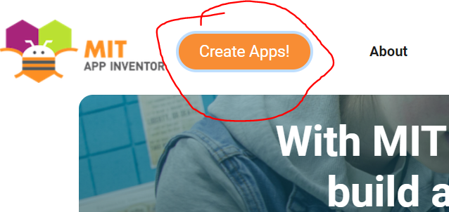
The first thing that you need to do is go to: https://appinventor.mit.edu/
Press the big button that says 'Create Apps!"
Then register an account and login.
Once you're at their dashboard you should press 'Start new project', and you should now be able to start making an app easily.
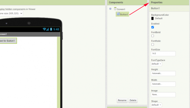
Once you're in the app inventor, you can drag and drop buttons onto the screen.

When clicking on buttons you can change them into alot of different things under properties. My best advice is to just try it out.
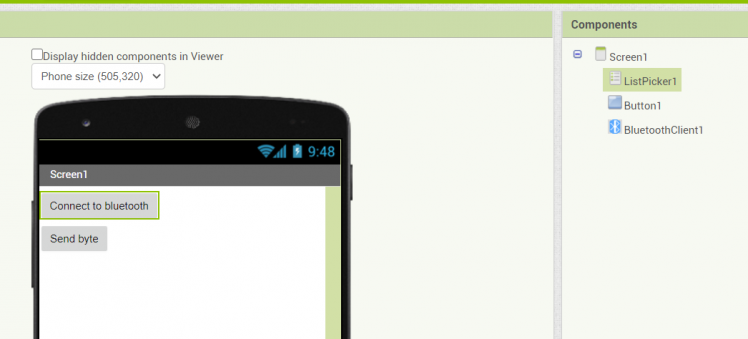
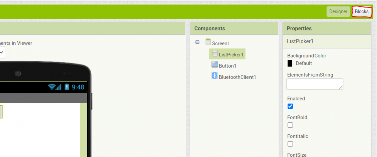
For now we will need one button and one listpicker. So add that.
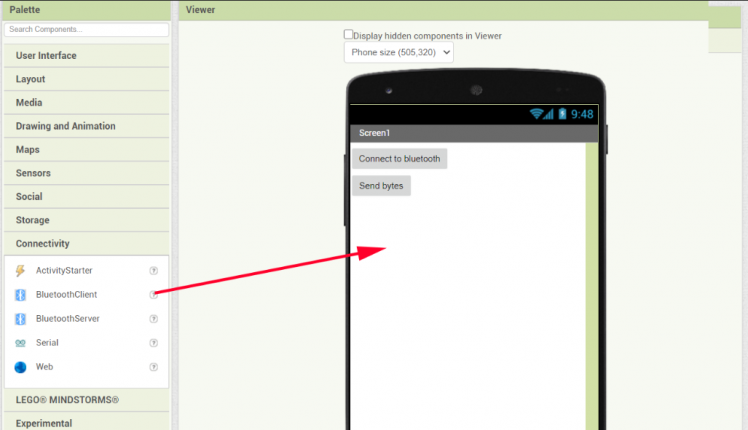
We will also need a bluetooth client. You find this in the 'palette' to the left under 'connectivity'. Simply drag the bluetooth client onto the app screen. It should appear in 'components'.
Now you should go to the far right corner and click on 'blocks'.
You can now begin coding your app. You can take anything from the 'blocks' and from the app itself and start block coding. Start by selecting 'when ListPicker1.BeforePicking'.
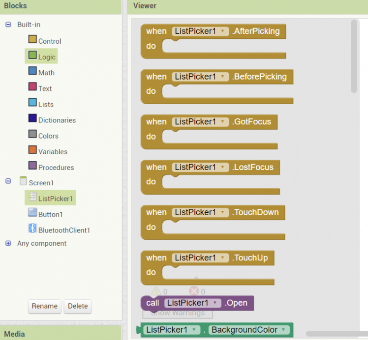
You'll find the relevant blocks under ListPicker1 and the BluetoothClient1. Set them up as I've down.
The first block "When ListPicker1.BeforePicking" shows will show you a list of all the available bluetooth devices that you can connect to.
The Second block "When ListPicker1.AfterPicking" will let you choose a bluetooth device and connect ot it. Your bluetooth module should be named something that ends in HC-05.
It will also change the text of the ListPicker to 'CONNECTED'. I do this as I like to know if it worked or not.

After that we can add a button that will send the arduino a byte. From the blocks list choose button1. You will find these blocks under the button block, bluetooth client block and math. When you set it up like this it will first send a '33' to the arduino and then just after that it will send a '3'. We can use this to make if statements and make the arduino identify what sort of command was send to it.

The code in the arduino will read these with mySerial.read(), save it as a variable and then excecute if statements.
- if (state==33 ){ //MODE MODE MODE MODE
- //We check the second incoming byte.
- if (mySerial.available()){
- state=mySerial.read();
- //This saves the incoming byte and uses it in the mode() function to decide what mode it should be in
- ModeChange=state;
- //This resets X (upwards sliding leds) to the opposite of I (the downwards sliding leds)
- if (ModeChange==3){
You can try and play around with it yourself. Add some more buttons, make it send other numbers. Try it out.
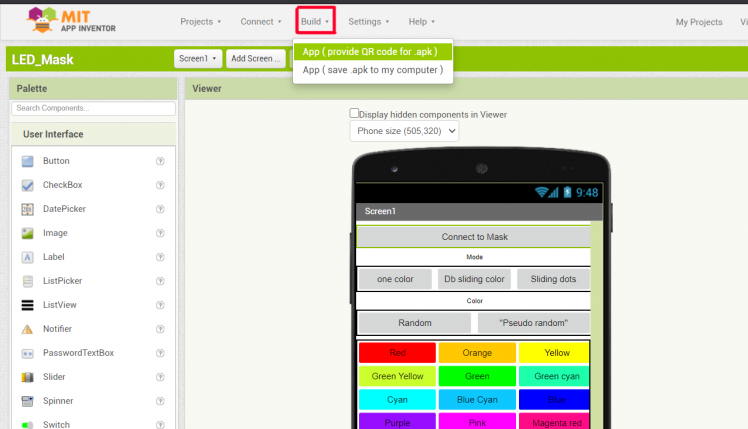
DOWNLOADING THE APP.
If you want to download the app, you should go to the app store on your android device and download the 'MIT AI2 Companion'. Once you downloaded that onto your device you should go back into the app building program. You should press build and then press 'App ( provide QR code for .apk)'.
A QR code should appear. You are able to download the app that you've made with the 'MIT AI2 Companion' app by scanning the QR code.
IF YOU JUST WANT TO DOWNLOAD MY APP:
You'll have to download my app by a zip folder and import it into the MIT App inventor. Here is my app: https://drive.google.com/file/d/12_tz7mRwRsx_EtHJQo8UGmunlRxtvVt7/view?usp=sharing
You import by pressing 'projects' and then pressing 'import (.aia) from my computer'. Afterwards follow the steps above about how to download an app.

You're welcome to edit and change my app and do something of your own with it. However it's built specifically for this project.
4. Getting the light right
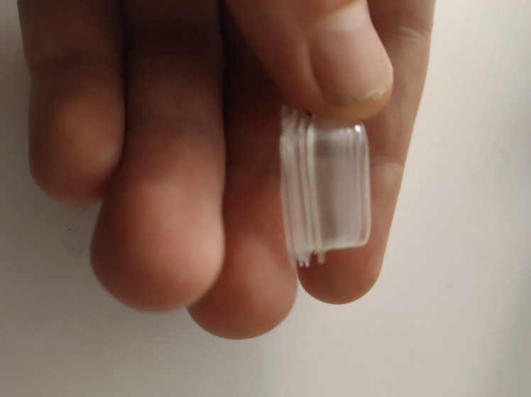
You want your LEDs to display on a white cloth surface, ideally a thin t-shirt that you cut out. White is really great at accepting color so use white. Ideally you'd wanna get the light to spread evenly throughout your mask. This can be quite a challenge. You want to make sure that the light from the LEDs are spread evenly out on the surface that they are displaying on. You must not set the LEDs too close to the displaying surface. This will make it look like there are just a bunch of LEDs behind your mask. To spread out the light from the LEDS you should place them some milimeters away from what they're displaying on. About 1 cm worked for me, but try it out for yourself. Test how far they have to be from the surface for it to look good. See picture for clarification. Imagine the square as the surface you want to display through.

Any kind of transparent plastic is fine. I used old pill capsules as the plastic that was keeping it about 1 cm from the display surface and it worked perfectly. I taped these onto the LED strips. Don't be afraid to use something strange. If it's stupid but it works it's not stupid.
5. Building the mask
I recommend using a airsoft mesh mask. You can use any airsoft mask you want, but it should ideally look something like the picture below.

You should then sew a white cloth (from a t-shirt maybe?) really tightly to the net. I recommend using black thread, as it blends in with the net nicely and won't be able to see it. That's what I used.
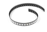
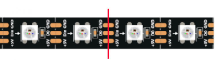
For the next part you should bring your soldering gear. You want to measure how many LEDs can realisically be in the mask. It's VERY IMPORTANT that you take the time to make sure that you're precise. Identify how many LEDs can be in each row, and cut out the LEDs according to how many you need in each row. You can cut the LEDs where the V, GND and DIN input meets the V, GND and DIN output. See picture.
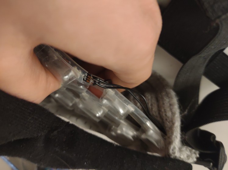
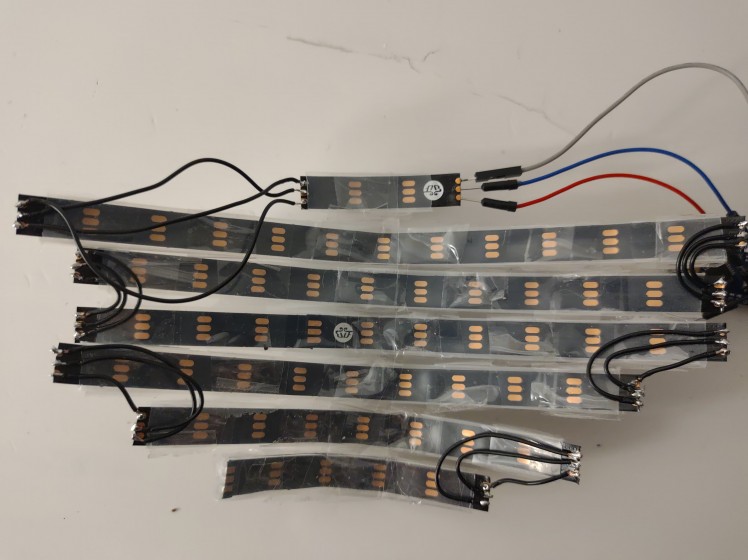
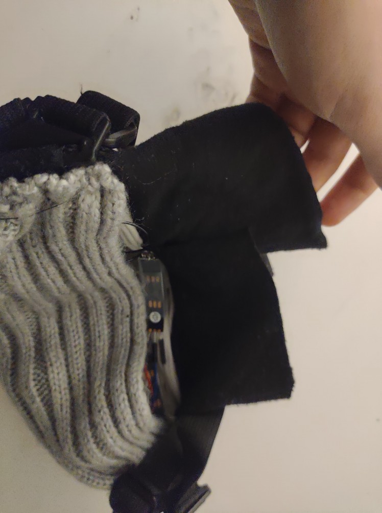
Once youre done cutting the LEDs you should form them and solder them together. I attached a picture of how my LEDs look like from the inside. You can use tape to make them stick together as a cohesive unit that's easy to take in and out of the mask.
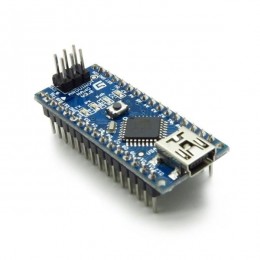
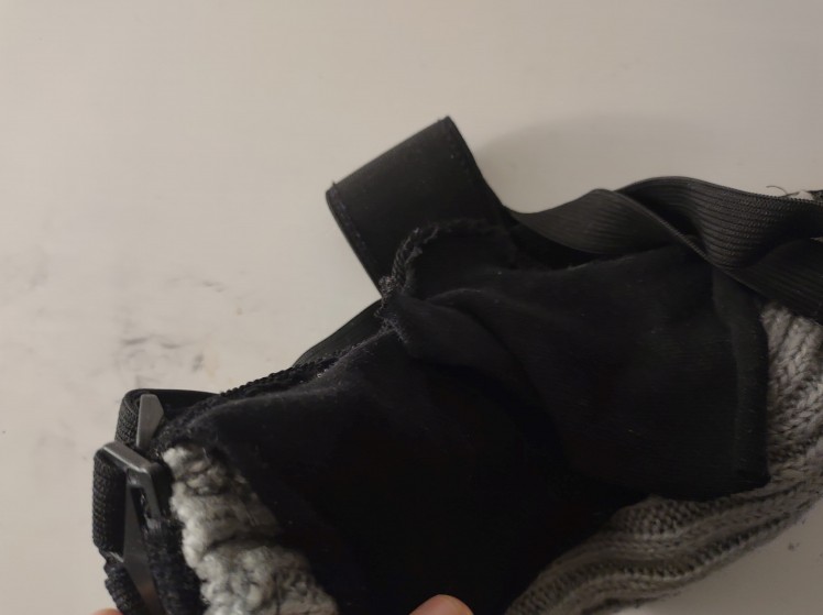
Once this is done, you should make a small pouch within the mask where the mask also connects with your face. This is for holding the LEDs and the other electronics. The arduino nano and the bluetooth device is so small that it shouldn't annoy you. If you think it might, you should consider what sort of cloth you want to use for your pouch. I used an old headband that I don't use anymore as the pouch.
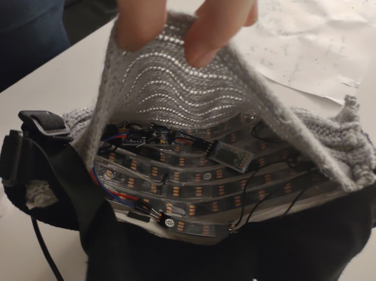
Once this is done you can put your LEDs inside and try out your mask! Does it look cool? Do you like it? Let me know.
There is one more optional step. Depending on how you've put your LEDs you might experience that the LEDs light quite alot and might blind you. Like this:
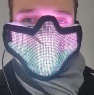
This is easily fixable. Just sew some black cloth flaps on top of where the light from the LEDs come from. This will easily prevent any light from reaching your eyes.

And now there's no light in your eyes when you wear your new mask!

As a last thing. I recommend you use a long wire and a powerbank (in your pocket) as the power source for this. It's way easier than working with batteries!
Additional tips:
Hot LEDs
If your mask starts to get hot from all the LEDs you should consider turning the brightness down with the code:
- strip.setBrightness(X);
X can be anything between 0 (off) and 255 (MAX).
Weather
Remember that though the mask is cool and you want to wear it outside, this design is NOT waterproof. If it starts to rain put it in a plastic bag or just check the weathercast beforehand. Alternatively find a way to make it waterproof. And don't worry. Breathing into the mask shoudln't do anything, just don't spit in it.
MIT App Inventor
If you're still confused about the app building process or want to add something that I didn't cover then search for tutorials on youtube. You'll find ALOT of resources about the MIT App Inventor.
And that is it! Thanks for making this project! Make some cool patterns in the code! Change it up a bit! I'd love to see what you do with it!
Happy building!
-Thor

Schematics, diagrams and documents
Code
Credits
Related products


Leave your feedback...