
Raspberry Pi Pico Audio Record, Play, Wav File

Made by DevelopIT / Music / Notifications / Sensors / Voice
About the project
This project has been designed to be a very simple and easy to understand, audio recording and playback system. Using a Raspberry Pi Pico and C programming language. It has the added facility to also save WAV formatted files, which can be played directly on Linux, Windows & Mac OS.
Project info
Difficulty: Moderate
Platforms: Raspberry Pi
Estimated time: 3 hours
License: GNU General Public License, version 3 or later (GPL3+)
Items used in this project
Hardware components

View all
Software apps and online services
Hand tools and fabrication machines
Story
OPERATION
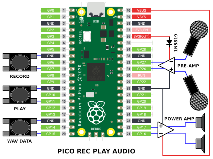
The project has three switches, each with a dedicated operation. The first starts an audio capture operation. Press the button, the onboard Pico LED lights for the period that audio is being captured from the microphone into the RAM of the Pico. Pressing the second button will play what ever audio is currently in the Pico RAM, also lighting the onboard Pico LED during the operation. And the final button will output the audio data from RAM to the Pico debug terminal as ASCII HEX values. The Pico LED will be lit during the transfer. If logged to a file, the file can then be processed with the HexDumpToWav program (source code also provided in the project). This will create a binary WAV file from the data, which can then be played from the host operating system.
USE CASES
The Pico has ~260KB of RAM, which will store stereo audio, sampled at a rate of 22050 Samples per second for about three seconds. Which provides enough for this project to demonstrate the capabilities of the process. But a process of capturing more audio is required for decent application. The simplest solution would be to either stream to a local storage medium such as an SD card, or stream the audio over wires or wirelessly via Wi-Fi.
Examples of local storage applications:
- Dictaphone.
- Seismology monitor (seismograph).
Examples of wireless storage applications:
- Intercom
- Walkie talkie
- Baby monitor.
- Lapel wireless microphone.
HARDWARE
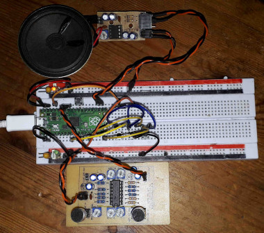
The hardware for the project consists of three parts:
A pre-amplifier for the microphone.
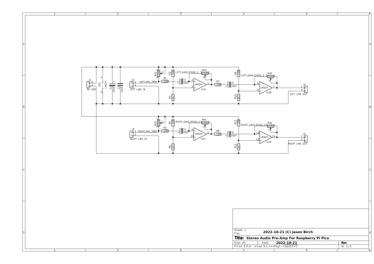
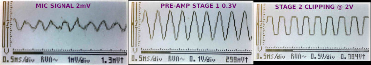
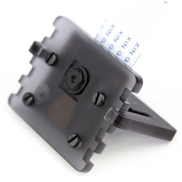
The microphone used in this example has the letters "SG" marked on the side. It varies resistance as it reacts to audio. When used in series with VR1 between the 3V3 supply for the Pico and 0V, it forms a potential divider to produce a voltage which varies with the resistance of the microphone when in use. This voltage is millivolts in amplitude, the Pico A/D converter requires a voltage which varies between 0V and 3V3 for best results. So the signal is amplified via a couple of op-amps. A single op-amp could be used, but as an LM324 is used two op-amps are available for each channel, left and right. It is probably better to use two per channel as each op-amp will not have to work as hard and may reduce unwanted noise. The pre amplifiers are configured as inverting amplifiers, each stage can be adjusted for best results with the type of microphone being used. Ultimately the POT resistors could be replaced with their fixed values. The resistors R3 and R4 form a voltage divider which sets the output voltage of the amplifier for when the input is 0V. This needs to be half of the power supply of the op-amp, with one caveat. The LM324 can output all the way down to 0V, but can't operate up to the supply voltage. So when supplied with 3V3, reduced to about 3V after the 1N5819 diode used to prevent noise from the power supply to the op-amp, the values of the resistors I have selected, bias the potential divider lower to account for this. Capacitors C3 & C5 remove any DC voltage from the audio signal, however the output of the op-amp U1B does not have the DC voltage removed as it is sent to the A/D converter on the Pico, which requires a positive voltage only. If the DC voltage was removed the audio signal would swing from positive to negative voltage.
The second part of the hardware is the LM386 power amplifier which amplifies the output of the Pico PWM pin to a current that can drive a speaker.
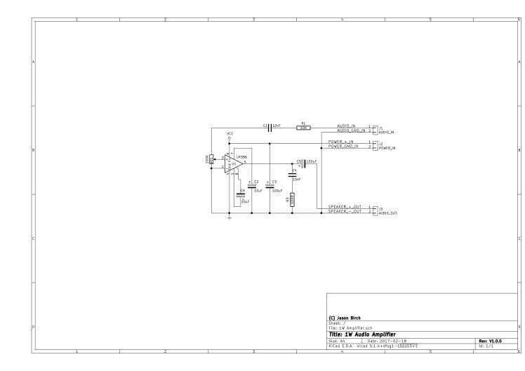
A pair of these amplifiers are required for a stereo system. The power amplifier is supplied directly from the 5V USB supply to prevent too much load on the Pico 3V3 regulator. This amplifier comes in several variants capable of different power outputs, the 1W version is used here, however any can be used as long as the one chosen is capable of enough power to drive the speaker chosen. Resistor R1 reduces the current available to the volume control, as the volume control can pull the signal to 0V. It prevents the GPIO pin output being shorted to 0V when outputting a logic 1. C1 removes DC voltage from the PWM output. It may seem strange as the PWM output is digital, this is a standard configuration for an amplifier input and is desirable as it will make the PWM voltage swing positive to negative, which is required to drive the speaker cone in and out. C2 and C6 set the gain of the amplifier. C4 and R3 filter high frequency noise from the output. And C5 removes DC voltage from the output.

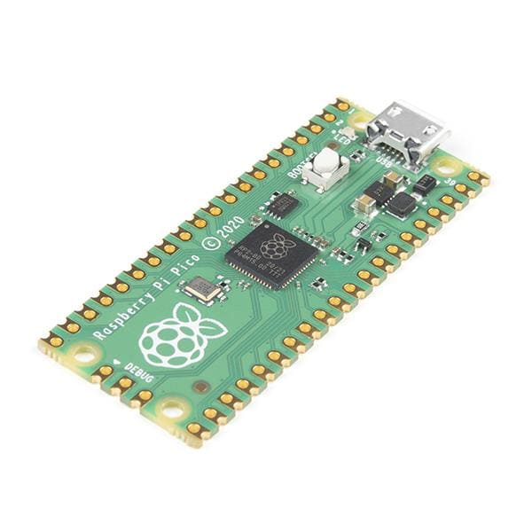
The remaining components are the supplementary components to complete the project. The Pico, switches, microphone and speaker.
SOFTWARE
There are two software applications. The main application running on the Pico, which will record audio, playback the recorded audio and output WAV file ASCII HEX formatted data, to the debug console. The second application converts the data captured on the debug console to a binary WAV file which can be played on the host system.
GitHub Source Code Repository For The Project
Capturing An Audio Sample
Recording audio with the Pico is a very simple process, extracted below are the few lines of code which perform the operation. The size of the audio data is stored in the first four bytes of the audio data. After that repeatedly two bytes are stored for a left channel sample, followed by two bytes for the right channel audio. A period is waited between each pair of samples in order to throttle the process to 22KHz, the period required is 1/Sample Rate seconds. The RAM of the Pico is large enough to store about three seconds of stereo audio sampled at 22KHz. After this the audio needs to be moved to a storage device or over a wired or wireless network before the next three seconds can be sampled.
- SampleCount = 0;
- AudioBuffer[SampleCount++] = (AUDIO_BUFF_SIZE & 0xFFFF);
- AudioBuffer[SampleCount++] = (AUDIO_BUFF_SIZE >> 16);
- SamplePeriod = time_us_64() + (1000000 / WAV_SAMPLE_RATE);
- while (SampleCount < AUDIO_BUFF_SIZE)
- {
- while(time_us_64() < SamplePeriod);
- SamplePeriod = time_us_64() + (1000000 / WAV_SAMPLE_RATE);
- adc_select_input(ADC_PORT_AUDIO_IN_LEFT);
- AudioBuffer[SampleCount++] = WAV_PWM_COUNT * adc_read() / 4096;
- adc_select_input(ADC_PORT_AUDIO_IN_RIGHT);
- AudioBuffer[SampleCount++] = WAV_PWM_COUNT * adc_read() / 4096;
- };
Playing An Audio Sample
Play back of the audio is just as simple as recording. The Pico has the hardware required to play sampled audio using only the DMA and PWM features. The software just needs to kick off the process. So the code below sets up a DMA transfer to transfer 32 bits at a time, which is equivalent to the two byte of left and two bytes of a right sample. The DMA transfers the data directly to the PWM hardware. When a PWM GPIO is configured, it is configured as pairs of GPIO pins, so two channels are automatically configured. In this example PWM channel 0 is being used for the audio playback, so the DMA just needs to send the sample data to PWM_BASE + PWM_CH0_CC_OFFSET. Now the program can do other things while the audio plays to completion. The playback API provided also offers features such as stop playing and query if audio is currently playing.
- WavPwmDmaChConfig = dma_channel_get_default_config(WavPwmDmaCh);
- channel_config_set_irq_quiet(&WavPwmDmaChConfig, true);
- channel_config_set_read_increment(&WavPwmDmaChConfig, true);
- channel_config_set_write_increment(&WavPwmDmaChConfig, false);
- channel_config_set_transfer_data_size(&WavPwmDmaChConfig, DMA_SIZE_32);
- channel_config_set_dreq(&WavPwmDmaChConfig, pwm_get_dreq(PwmSliceNum));
- dma_channel_configure(WavPwmDmaCh, &WavPwmDmaChConfig, (void*)(PWM_BASE + PWM_CH0_CC_OFFSET), &(WavPwmData[2]), (WavPwmData[0] + (65536 * WavPwmData[1])) / 2, false);
- dma_hw->ints0 = (1 << WavPwmDmaCh);
- dma_start_channel_mask(1 << WavPwmDmaCh);
Downloading Audio Data
To download the recorded data to a host computer over USB, use the minicom terminal application. Start it in a command line window on Linux as follows:
minicom -b 115200 -o -D /dev/ttyACM0
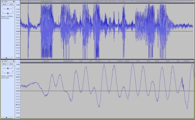
Then log the output to a file, ensure the file does not exist first as the data will be concatenated to the end of an existing file. Press CTRL+A then press L to start logging. Then press the third key switch on the Pico project. The data for the audio will be sent to the terminal. After the complete data has been received, press CTRL+A then then press L to close the log file. The data downloaded is an ASCII HEX dump of the captured audio. An example of the start and end of data can be seen below. Pass this file into the HexDumpToWav application to produce a binary WAV file.
./HexDumpToWav [FILENAME]
The result will be a file named [FILENAME].WAV
- ----- WAV DUMP START -----
- 52494646B809040057415645666D742010000000010002002256000044AC00
- 00020010006461746194090400
- A9DFAE3172E4F53011E7B12FDEE997317EEBF431ABEC0E3079EE
- 6C2F76F0552F74F1B52D8AF2FF2A11F5162B6EF52F2A55F68F289EF490276EF5
- 1E269BF61E26F7F6BD283CF77C256BF7B61E52F8EB1AAEF85E1B6CF6751B6CF6
- 8E1AB2F6301BDEF7191B52F8B81D97F8FA1FAEF8CA207FF9B61E50F93F2009FA
- 552196F9552138FA9F1EF4F86C217DFA55217DFA9C2069F8591E39F9FD1D97F8
- ...
- 53147FF93B1469F83B14AEF83A150BF91C19AEF8DF1350F9AD15ADF94F167DFA
- F315F1FA6A140DF8381697F8961550F91E18ADF91E18F2F94F167DFAAD15ABFA
- 0C1569F8951697F84E177FF9F61350F94F16DBF9AC1669F80A1696F9F01750F9
- 7E16F4F86B13F4F80A1639F91F17ADF93A1509FA9814F2F9AD1599F79D1197F8
- 3D1309FADD143BF81F1769F87E1697F8961552F80D140DF8B113
- ------ WAV DUMP END ------
Schematics, diagrams and documents
Code
Credits
Related products


Leave your feedback...