

Raspberry Pi + Esp32 Drone (or My First Steps Into Robotics)

Made by tohntobshi / Drones / Robotics
About the project
Rapsberry Pi + ESP32 based drone with custom flight controller logic, which uses opencv for position control. At the current stage it can hold its postion indoors. It has android app as a controller.
Project info
Difficulty: Difficult
Platforms: Android, Raspberry Pi, Espressif
Estimated time: 7 months+
License: GNU General Public License, version 3 or later (GPL3+)
Items used in this project
Hardware components


View all
Software apps and online services
Hand tools and fabrication machines
Story
Hello everyone! I'm not sure how to frame this project into tutorial how to replicate it, because there are a lot of things to do. Should I say learn this programming language and implement this algorithm, or just grab my codebase and compile it, etch this PCB or connect the modules with wires and so on. Also there are a lot of subjective design decisions that some people may question. And someone capable of replicating it, will probably prefer their own way of making such a thing. So it's not an instruction, but rather a story, somebody may be interested in, or get inspired, or borrow some ideas. I also added a video about it and links to the codebase in the end of the article.
So here is the story of my first steps into robotics and particularly about my Raspberry Pi + ESP32 based drone.
Preface
At the beginning of the story I was working as a web developer (React, Typescript, etc), had some C++ knowledge, as for electronics skills — I could solder ripped headphone wires. The problem was that being a web developer I started to feel dissatisfied because what I do doesn’t affect the physical world in any meaningful way. Of course, there are a lot of software-only projects that impact the real world but I decided to take the most straightforward approach and dive into robotics.
So I read some books on the subject, watched some videos on youtube, read some articles, and bought soldering equipment and a 3D printer, as 3D printers are cheap and available nowadays and can spare me the headache of making parts out of food containers and similar junk.
The first robot
My first robot was this caterpillar platform:
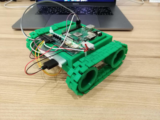
I designed parts in Blender and then printed them. I used Raspberry Pi as its brain and a power bank as a supply. I soldered the motor controller out of relays and transistors. In the process of making this thing I encountered one problem, when I assembled everything, the motors were barely moving. It turned out I mixed up the collector and emitter of the transistors, and after resoldering them everything started to work. It’s hard to call this thing a robot because it doesn’t do anything on its own and is only remotely controlled. Anyway, I felt great about making it, believed in myself, and decided to make the same thing but a flying one.
The second robot
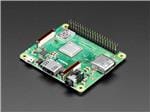
After some research, I decided to use some conventional quadcopter parts such as brushless motors, electronic speed controllers, and a lipo battery capable of providing high current to the motors. As a brain, I still used the same Raspberry Pi. After I found out how to interface Raspberry Pi with ESCs I started to design a frame to hold all the parts. I was doing that relying only on intuition in the hope that requirements for a frame are not very strict because I saw drones of such weird shapes that were still able to fly.
I also bought a board incorporating a gyroscope, accelerometer, barometer, and magnetometer on the i2c bus. Before I even learned what a PID controller is, my first intuitive approach was similar to the way its P component works — just increase or decrease motor speed proportionally to the angle the drone diverges from the horizontal plane.
In the beginning, I thought that it wouldn’t be a very difficult task but after all the failed attempts I had no idea how to do this the right way because there are so many things that may not work properly. And contrary to making something software-only, every run may end up with physical damage and the next try will be possible only after damaged parts are replaced. Also, it is not that easy to test this thing in a small rented flat. Had I had a big garage, shed, or something like this I could have made construction that would restrict the drone’s motion.
Instead, I had to improvise and use shoelaces and my own hands which sometimes led to minor but unpleasant injuries.
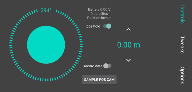
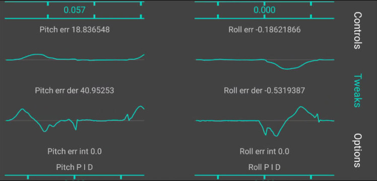
At some point, I thought that it is not convenient to control the drone with a mouse and keyboard and decided to make a controller app, where I can change parameters, monitor sensor readings, and gradually control the drone with analog-like UI.
Initially, for some reason, I focused on horizontal leveling control just to realize that I cannot safely test it and what I needed more is automatic height control. My first thought was to use barometer readings but they were not precise enough to control height indoors (or maybe I just used them in the wrong way) so I bought an ultrasonic sensor in a local electronic component shop. Actually, it had a weird interface that turns one of the pins high during measurement and you have to count time to deduce the distance. When the Raspberry Pi was relatively idle it worked fine but under computational load it just missed timings and the readings were garbage. So I had to add an additional AVR controller to the project solely to measure these timings and output results in convenient digital form on the SPI interface.
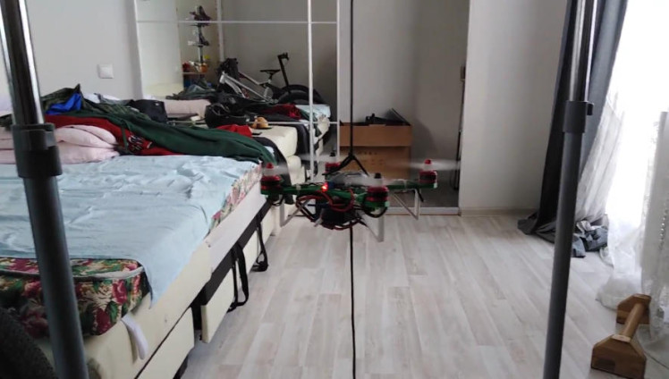
I also bought two bicycle brake cables and printed guides for the drone to restrict its motion to up and down so I could focus on height control without thinking about controlling other degrees of freedom.
And it kinda worked except for the case when propellers were working, creating turbulence which interfered with ultrasonic sensor readings at heights above 40cm. When I finally found it out I had to replace the ultrasonic sensor with a laser one.
At that point, I already had height control but still couldn’t achieve stable horizontal leveling, even though I had implemented PID control for it. I guessed several reasons for it and I am not sure which of them contributed to the problem the most. But here they are:
For the first one and probably the most significant, I used cheap propellers (and even tried to print them) and neglected the necessity to balance them, which in turn overloads IMU sensors with noise which reduces their precision. When I finally decided to address this issue I added a feature to my app to take the last 100 gyroscope readings and output range between the biggest and smallest value. The bigger the range when the propeller is working the more unbalanced it is. I randomly stuck duct tape to the blades of propellers, then run them to check the value, if it is increased — probably a bad place to stick there, if the noise is decreased — I am on the right path, then I tried to stick it further or closer to the center and check again, so this way I reduced the noise on each propeller.
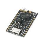
The second possible issue is that Raspberry Pi only has only two PWM channels, but there are four ESCs controlled with it, and software PWM may be not precise enough and also wastes CPU cycles. So I decided to use ESP32 for this task because they are cheap, easily available, and have a lot of interfaces that Raspberry Pi lacks. I started with controlling ESCs through ESP32 connected with Raspberry Pi over SPI and ended up moving all the flight controller logic to ESP32.
The third issue was probably not a rigid enough frame, which I redesigned and printed several times.
Another issue is suboptimal coefficients for the complementary filter I used for estimating incline angle. The optimal is 0.999 for the angle estimated by integrated gyroscope readings and 0.001 for the angle measured by the accelerometer.
I didn’t consider that pitch turns into roll and vice versa if the inclined drone is rotated around its local z-axis.
Very slow oscillations of incline angle may be fixed by increasing the P coefficient several times instead of decreasing it as some sources suggest.
Somewhere in the development process, I got frustrated with the number of wires between the modules and the way they were placed. So I decided to invest some time in the skill of making custom PCBs. I thought about it for a long time but was discouraged by the necessity of buying expensive tools and dealing with chemicals.
Actually, it turned out easier than I thought, I watched some tutorials on KiCAD to create the design of my PCB. I bought a second-hand laser printer for 40$, also bought a regular iron without holes for 5$, and the most expensive tool was a drilling press for 75$. The chemicals turned out to be not so dangerous, they won’t dissolve your skin if you touch them.
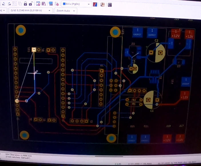
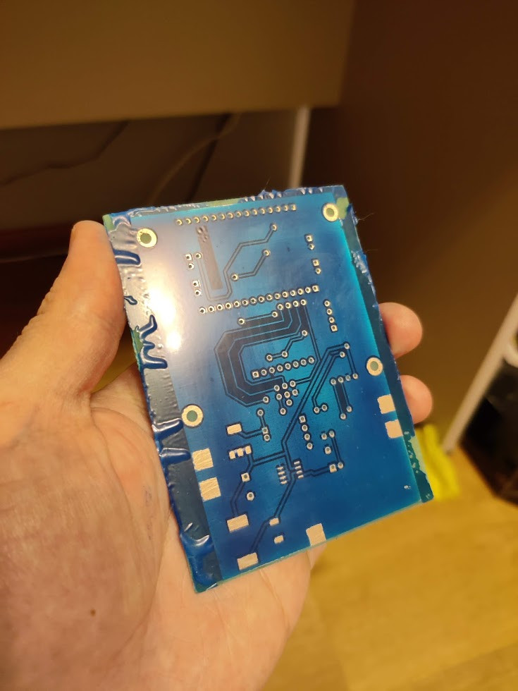
So I made this PCB on the fourth attempt. The hardest part was actually applying the solder mask. What this PCB does is that it interconnects sensors, ESP32, and Raspberry Pi and delivers appropriate voltage to different parts.
The fancy charts which show current sensor readings in the app turned out to be difficult to analyze while trying to prevent the drone from crashing. So I added the ability to record the sensor data and wrote a python script to analyze it frame by frame with the video record of the flight.
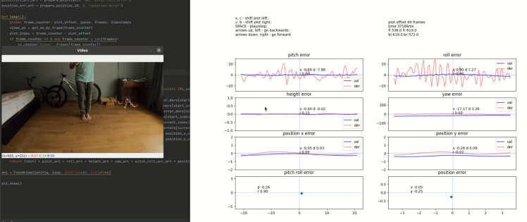
Had I done that earlier I would have spent much less time investigating problems caused by the faulty ultrasonic sensor which I mentioned previously.
At some point, I achieved relatively stable height, direction, and horizontal leveling control but still couldn’t avoid horizontal drifting. And if someone knows is it possible to get rid of horizontal drifting using only IMU sensors, please, let me know in the comments.
I did some research and I found out that some drones use GPS for position hold and I tried to implement the same technique. But the problem is that it works only outside, but even outside I couldn’t achieve any satisfactory results. The weather was terrible that season with wind, rain, and snow, so I didn’t make many attempts, bailed with GPS, and tried a computer vision approach.
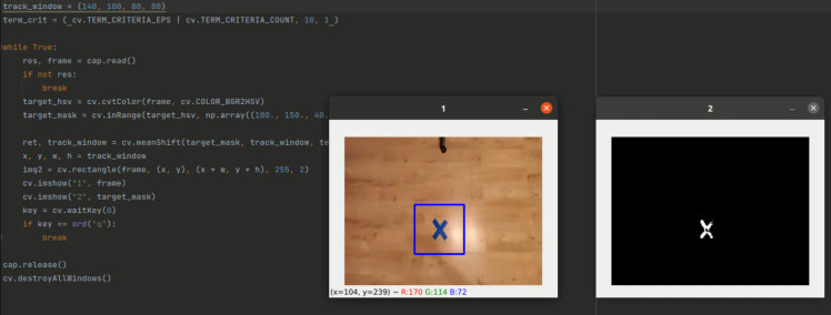
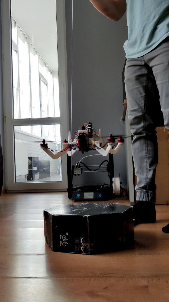
I placed a camera on the bottom of the drone and tried to hold this blue mark on the floor using OpenCV library. After several attempts and tweaks here is the result:
Now it can hover at one point without manual control and without any strings. This was my intermediate goal which I finally achieved, so I decided to document and share my progress.
I also added the transfer of a video stream from the drone to the app, so now I can experiment with computer vision to try different approaches to make the general position hold without special marks on the floor and to make other features.
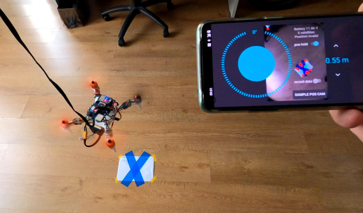
In the current configuration, the drone is made like this: ESP32 is responsible for height, direction, and leveling control. It takes data from IMU sensors and a laser distance sensor on the bottom. It gives commands to motor controllers and also it takes commands from raspberry pi, which itself is responsible for communication with the app and position control using data from the camera.
If someone is interested to see the code
The code isn’t very clean, as I changed implementation frequently trying to make it work properly. Maybe I will clean it up in the future :)
Also, I made a video about it:
Thanks for your attention! Cheers!
Code
Credits
Related products


Leave your feedback...