
PSoC 4: The Auto Ranging Multi-Meter

Made by electrouser805
About the project
An auto ranging meter with diode/LED, resistance, capacitance, continuity testing capabilities. No Voltage or Current measurements !
Project info
Difficulty: Moderate
Platforms: Adafruit, Cypress, SparkFun
Estimated time: 1 hour
License: GNU General Public License, version 3 or later (GPL3+)
Items used in this project
Hardware components


Story
Meters are Meters!
For someone who is a hobbyist/pro-developer/engineer, it never hurts to have a spare meter! This is the story of a hobby meter, named DRCC meter. DRCC stands for Diode Resistance Capacitance and Continuity testing meter.
Features
- Auto ranging resistance measure: 10 Ohms - 500 kOhms
- Auto ranging fast capacitance measure: 1 uF - 4000 uF
- Diode/LED with forward voltage drop: < 2.0 Volts
- Continuity of circuit trace/wire < 100 Ohms
- Fast update
- Capable of measuring big caps
- Cool icons for components
Simple Hardware & Working Principles
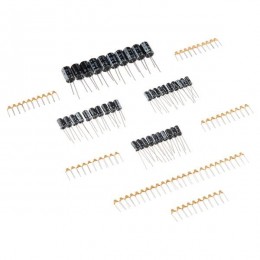
The hardware is very simple. Just a PSoC 4 4$ kit on a breadboard, few resistors, a buzzer, a 20x4 LCD Character display and 2 connecting probe!
Resistance
From Ohms law V = I * R or R = V/I, injecting known I value and measuring the V with ADC, resistance R can be calculated. The current injection is done in PSoC 4 using IDAC module. Details explained Here from a old project with just resistance measurement capability.
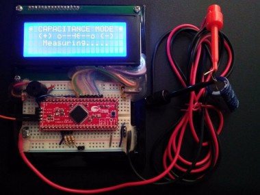
Capacitance
As for Capacitance, C = Q * V, means Capacitance is equal to Charge Q stored in a capacitor times Voltage build up across capacitor terminals. Again, Charge Q = I * t, meaning Current times Time is Charge. Now, injecting a known current for a known time, total charge stored can be calculated. During this charge storage voltage V will build up which is measured using ADC. Finally, capacitance can be measured from multiplying all the measured value C = V * I * t .
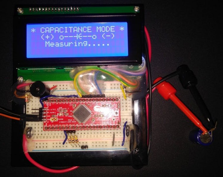 1 / 2 • Measuring big caps
Continuity
Continuity of any electrical path means Low Resistance. It can be measured in the same way resistance measurement.
Diode/LED
Diodes exhibit a forward voltage drop known as knee voltage where diode voltage pretty much locks up. By applying full IDAC current through diode or LED this voltage drop can be reached. Next the ADC is used to measure up the FW voltage drop. If there is 0 Volt drop means the diode is Bad/Short.
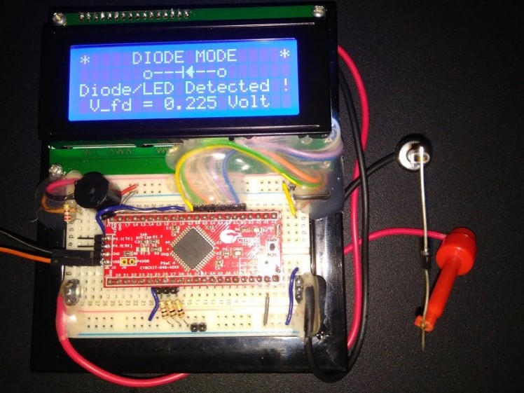 Diode Test
What is IDAC?
IDAC is a Digital to Analog Converter Current Source. It can source/sink of current which is programmable.
- IDAC can be shorted to Ground or V supply, without any harm
- IDAC pin goes to 5 volt when set current can not flow through load
- IDAC consumes Analog Routing/paths inside PSoC
- IDAC has current step of 1.2 uA or 2.4 uA
- IDAC current step current's Integer Multiple in 7/8 bit can be programmed
Magical Firmware
The PSoC Creator (version 3.1 used) is a magical firmware allows to add the cool components and wire up internally the hardware parts, so the complication on external hardware is minimized.
An ADC (12 bit) is used to measure, an IDAC (8 bit) is used to inject known test current to external components, timer to keep track of elapsed test time, LCD component drives the display with breeze, few GPIO pins to change options and press indication on LED. Measurement and current inject is done with an analog pin.
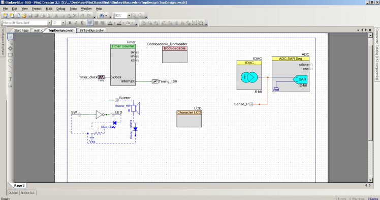 1 / 2 • PSoC Internal Schematics
PSoC Components Configuration
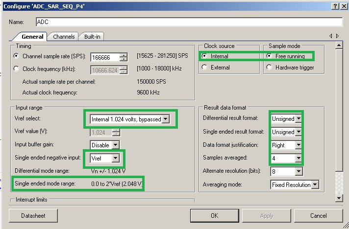 1 / 4 • ADC Settings
LCD icons for ohms, resistor, capacitor, diode etc are made using custom fonts as follows in the LCD component.
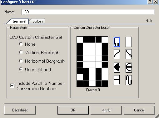 Graphical Icons
LCD is connected to Port 0 Pins: 0-7 as per following table from datasheet:
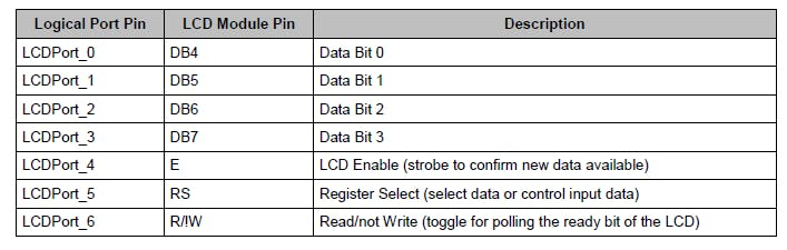 PSoC to LCD Hardware wiring
More Videos
Few more videos on separate tests:
Capacitance Test Resistance Test LED (Diode) TestSchematics, diagrams and documents
Code
Credits
Related products


Leave your feedback...