
Programmable Pocket Power Supply With Oled Display

Made by electrouser805
About the project
A programmable, portable, rechargeable power supply based on Arduino featuring an OLED display for viewing V.I.P. of projects/prototypes.
Project info
Difficulty: Moderate
Estimated time: 1 day
License: GNU General Public License, version 3 or later (GPL3+)
Items used in this project
Hardware components


View all
Hand tools and fabrication machines

Story
The Idea
As hobbyist people, we frequently need to power our prototypes, check voltage, current, power limits of our projects, test a newly bought component. The need of a variable power supply is always there in this line of work. But unfortunately, not all of us have bench/lab power supplies. It's also expensive if bought, bulky if needed to carry. I was looking for a programmable power supply at a lower cost, with portability and productivity for powering my prototypes and testing components. So, I decided to make one.
It has the following features:
- Programmable
- Rechargeable
- Portable
- Step Variable
- Voltage/Current/Power Meter
- Protected Relay
- Customizable, Compact and Cute
- Cool OLED User Interface
- Push Button User Control and Menu-based Navigation
- Firmware Upgradable for more features!
And most versatile power supply for low power electronics projects.
Live Action!
Check out this video demonstrating the device operation:
Charging Overload Voltage Current Power Change Demonstrated !Spec of the Device
The device has following specification:
- Max Output DC Load Current: 400 mA
- Voltage Range: 2.0 Volts - 12.0 Volts
- Voltage Step: 0.1 Volts Approx
- Best Efficiency: 75 %
- Current Measurement Accuracy: +/- 1 mA
- Voltage Measurement Accuracy: +/- 0.02 Volts
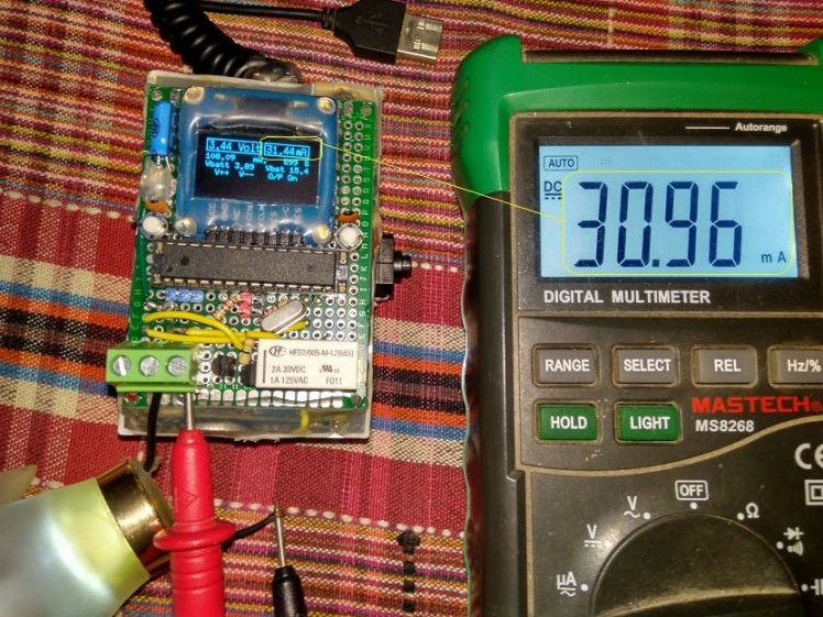 Current measurement check with external Multimeter in series
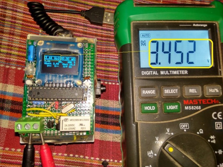 Voltage measurement check with Multimeter
Please note that this device is a quick prototype. It is possible to make 0-30, even Negative Supply and more Output Current by using high capacity batteries, additional electronics and upgraded design.
Working Principle
The design itself is hardware intensive. Lots of stuffs happening here. A crude block diagram of the system is something like this:
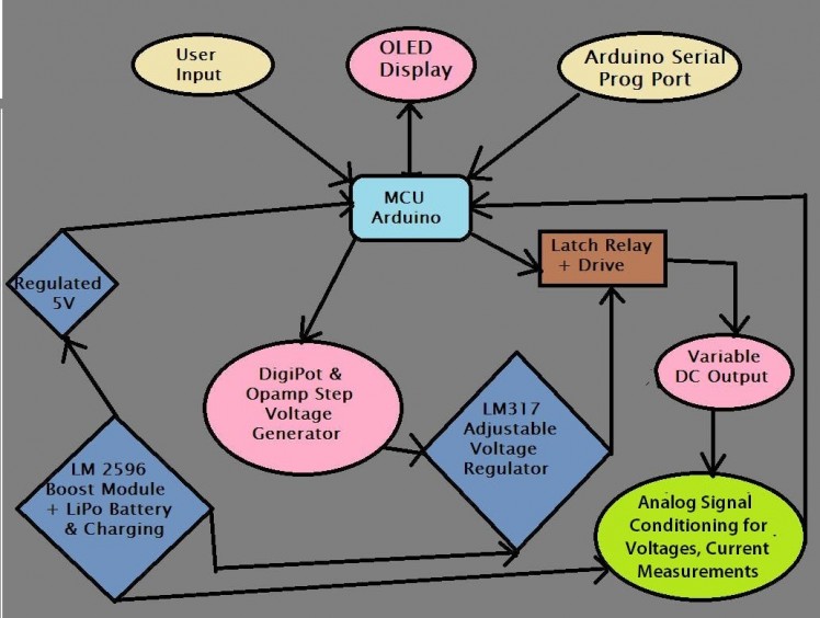
Source of power is the 3.7 V Li-Po Battery which is USB rechargeable. Using a XL6009 DC-DC boost module first we make 15.6 volts from the Li-Po. To run the MCU we also make a 5 Volt using 7805 Regulator.
The Arduino UNO clone Atmega328P is connected with 2 Interrupt based User Input Switch, an Elegant OLED Output Display. Rx/Tx/DTR firmware (sketch) upload port through USB/Serial from PC. (module 1)
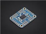
The Heart of the project is the MCP4131 Digital Potentiometer (Digipot) + LM 358 OpAmp based Step Voltage Generator. This voltage is the Control Voltage of LM317 Adjustable Regulator. (module 2)
Digipot is controlled from the Arduino through Pseudo-SPI like command. LM317 is designed such a way that the Output Pin Voltage is always 1.25 Volts higher than the Adjust Pin Voltage provided that the INPUT Pin's Voltage is high enough (here 15.6 volts). (module 3)
The step voltage is fed to the Adjust Pin to create variable Output from the Arduino as needed by the User.
The ADC measures all the voltages associated with supervision and protection; battery voltage, boosted voltage, charging sense voltage and output voltage are conditioned through voltage divider network for feeding the ADC range, which is 0-1.1 volts here. I have used the INTERNAL REFERENCE of Arduino which creates an reference voltage of 1.1 volts.
For the current sensing, the return (Load Gnd) from the Output Load is connected in series with 1 Ohms Current Sense Resistor to the System Gnd. When current flows through the external loads, there is also a voltage drop in this sense resistor. This voltage is amplified through OP07 Precision Operation Amplifier and fed to one of the ADC pin.
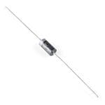
Lastly, for the battery charging, 5 volts from the USB is connected in series with a 4007 diode and a 5 ohms current limiting resistor to the Li-Po Battery. This is a crude charging method, not the best for Li-Po charging.
Operation Summery: The MCP4131 Digital Potentiometer creates step voltages with in 0-5 Volts range in step of about 40mV (7-bit 10K Digipot has 129 steps 5V/128 = 0.40 mV), which is then 2.5 times amplified by the LM358 that gives 0-12.5 volts control voltage range with steps of 0.1 volt. This amplified step voltage signal is fed to the Adjust Pin of LM317. LM317 generates an output voltage of V_Step+1.25 Volts which is supplied to the external loads. The return/ground of the external load is connected to the internal ground through 1 Ohms Current Sense resistor. Suppose: x mA current is flowing to external load, it will create x mV drop (Ohms Law V=I*R) on the 1 Ohms Current Sense Resistor. This small voltage signal is fed to Low Offset (10uV) OpAmp OP07 configured with 2.5X gain, which will generate 2.5x mV Output. The Arduino ADC is configured with 1.1 Volts internal reference so that voltages form 0 -1100 mV can be sensed in step of about 1mV (1100/1023). Output of OP07 is connected to Arduino ADC for current sensing. This is why the current limit is 400mA. It can be increased/reduced by changing the gain of OP07. Similarly output voltage range can be changed by changing the boost voltage & gain of LM358. Other voltages are measured with resistive voltage divider network attenuating voltages to fit the ADC Range. The latch relay has 2 coils. By applying momentary power to any of the coil, relay contacts can be switched. Once switched it remains there, so the coil is powered off immediately.
Building the Project
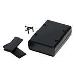
First we start with a single switch socket box, and make necessary cuts and alignments for placing the battery, USB charging port, power switch, etc.
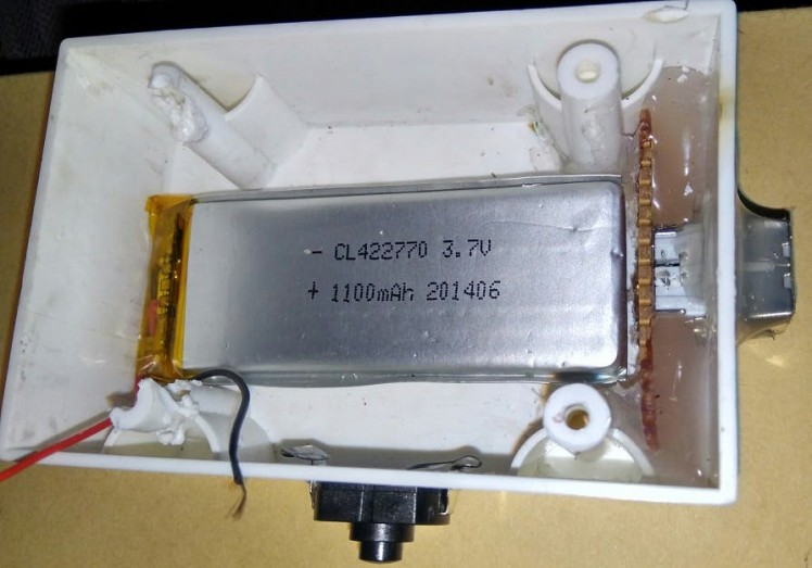 Battery Placement
Next, heat sink is made with copper tape and coin for the DC-DC boost module.
; ;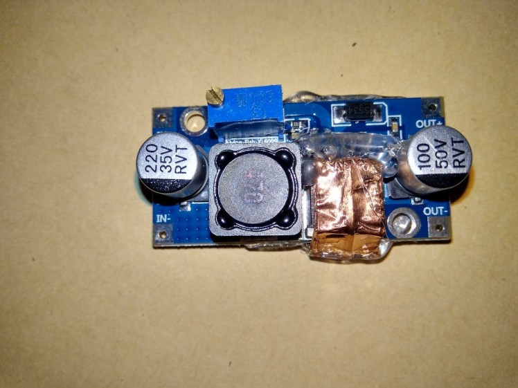 1 / 2 • Heat Sink
The boost module is placed inside the socket box:
 DC Module Placed
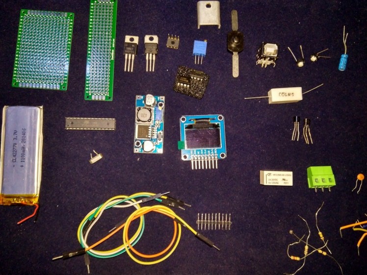 All the pieces before Soldering
Using the above parts, the following 3 modules are made:
- Arduino + I/O + Control Module
- Step Voltage and Adjustable Regulator Module
- Current Sensing Module
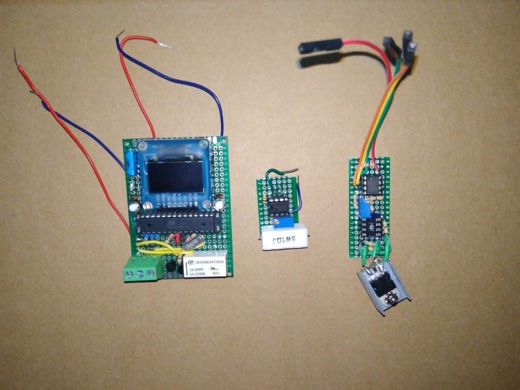 1 / 2 • 3 modules
Finally the spider web connections among all the boards are connected and soldered.
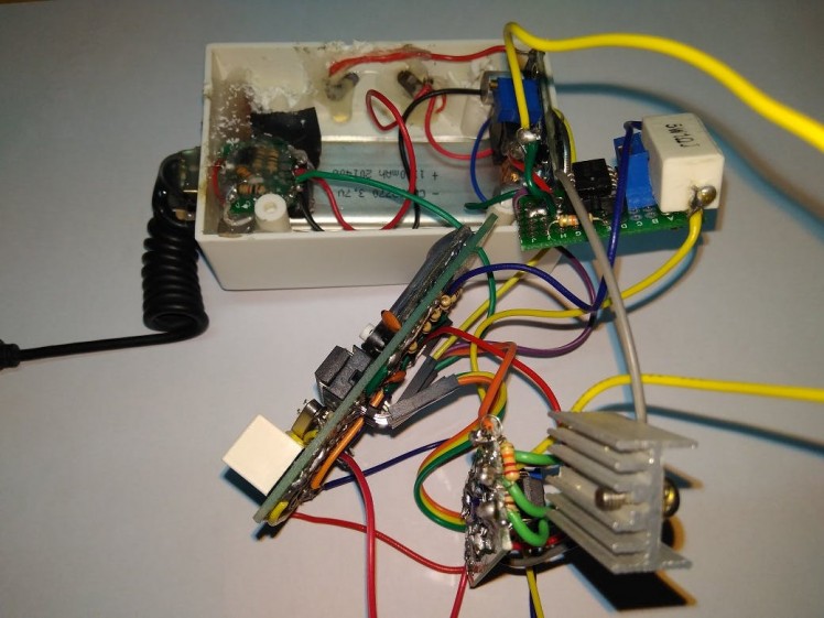 Interconnection !
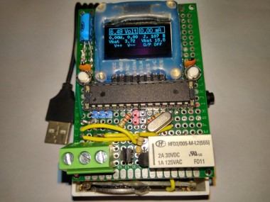
After using the hot glue as a filler, finally we have it:
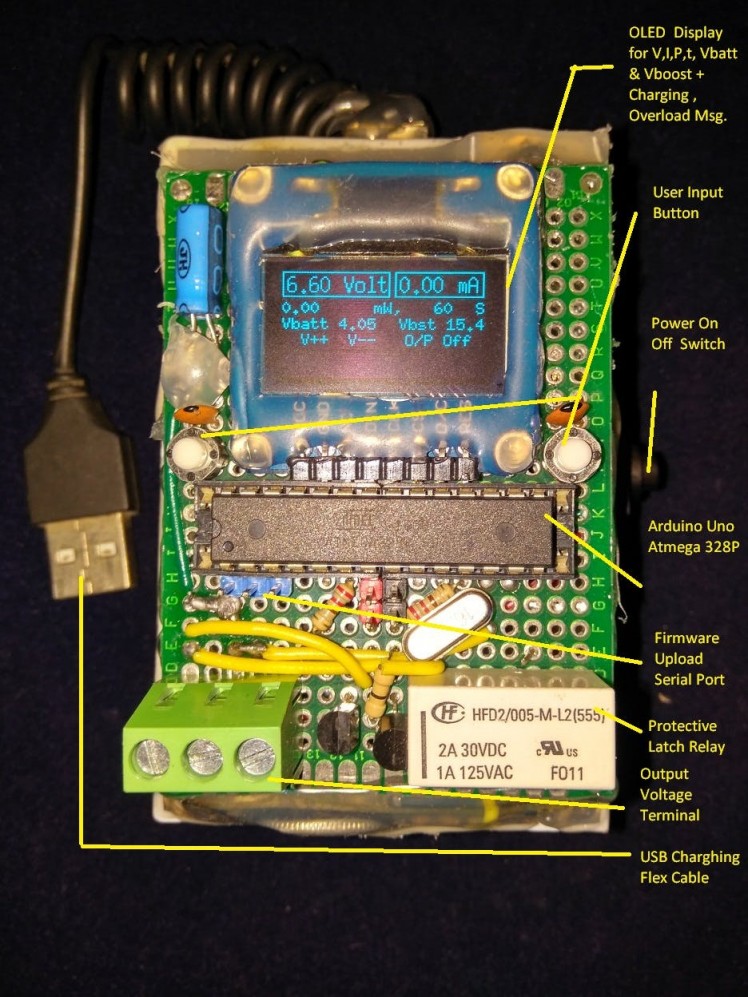 Arduino Power Supply
Developing the Firmware & Operating Procedure
The firmware (Arduino Sketch) is right now 1.0.2 Beta. Not all features are available right now. But most important features like controlling voltage, connecting/disconnection relay, viewing information are enabled. In the void setup() there are few initialization functions to warm up the Arduino pins associated to different external hardware.
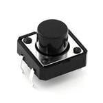
INPUT: There are 2 interrupt-based input button for increasing/decreasing output voltage, access menu (not available on this version). INT0 & INT1 on Arduino Pin 2 and 3 are coded for FALLING EDGE INTERRUPT. You will see 2 capacitors in parallel with mechanical switches for de-bouncing. Code is written to trigger interrupts when user presses these switches to turn on/off output through relay or increase/decrease voltage (Beta).
OUTPUT: The 1306 OLED shows output information acquiring data from ADC, internal timer (for device up time) and flag variables to inform user about Output enable/disable status. Based on U8G library the OLED prints info as text and numerical. I have plans for using graphical (Analog type) representation.
5 digital pins of SSD1306 (OLED from Waveshare) clk,din,cs,d/c,res are connected to Arduino 10, 9, 11, 13, 12 pins and programmed accordingly. In the main loop update_display() function is called every time to update the info on the OLED.
Internal Timer 1 of Atmega328P in configured to periodically trigger every 1 sec to keep track of time.
CONTROL: The MCP 4131 Digital Potentiometer is controller with increment_digipot() & decrement_digipot() functions where data is shifted out with proper clocking and delay using Pin 6, 7, 8 as CS, Clk, Data Pins. It's like slow soft SPI. Since I have already used up Hardware SPI pins somewhere else, this was the only solution then.
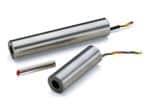
Two digital pins 4 & 5 are used to control the latching relay. A short high pulse is fed to the relay driving transistors to energize the 2 coils to flip the relay. It happens both automatically (during overload/short circuit) or manually by the user .
ADC: The calc_VI() function in the main loop performs analogRead to get 20 times averaged Voltage and Current information and updated the variable for new information which is then printed on the display
The sketch is written in multiple tabs to organize code for different functions associated to different operations. There are ADC, Digipot, Display_Fn, Interrupt, Relay and Timer tabs arranging all the user defined functions. I will try too add more comments explaining all the functions, but you should not find it hard to understand because those functions are based on multiple Arduino functions doing certain tasks.
Conclusion & Limitation
This programmable power supply will help me to make projects/prototypes more efficiently. The OLED is cool, loving it!
Measurement of voltage current power will help for precognitive analysis for other projects.
There are some serious limitations of this device:
- Voltage can't go below 2.0 V
- Voltage output is stepped not continuous
- Current measurement creates ground shifting for high current
- ADC measurement has low resolutions
- Efficiency is the worst in class at low voltage high current loading
- Non-standard, slightly unsafe Li-Po charging
But it does the job, because good enough is perfect.
Schematics, diagrams and documents
Code
Credits
Related products


Leave your feedback...