
Portable Iot Console For Sensor Interfacing "picsi"
About the project
The Cypress PSoC 6 WiFi-BT Pioneer Kit has multiple sensors and and a great user interface that make it ideal as a platform for sensor interfacing and experimentation. My project will demonstrate some of those capabilities developed using the Modus ToolBox as the development tool.
Project info
Difficulty: Moderate
Platforms: Cypress
Estimated time: 1 week
License: GNU General Public License, version 3 or later (GPL3+)
Items used in this project

Software apps and online services
Story
Overview
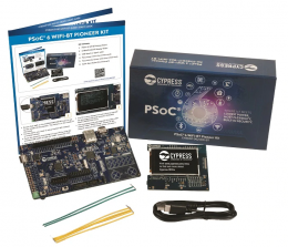
The primary goal of this project is to create a development environment (hardware and software) to evaluate IoT sensors. The Cypress PSoC 6 WiFi-BT Pioneer Kit includes a CY8CKIT-062-WIFI-BT Pioneer board and a CY8CKIT-028-TFT Display Shield that provides a convenient hardware platform for interacting with sensors and displaying sensor results. For software development, I am going to use the Modus Toolbox with the Eclipse IDE.
PSoC 6 WiFi-BT Pioneer Kit setup
The physical setup of the hardware is straightforward, just need to attach the display shield to the main board and connect to the host computer using the primary USB-C connector (on the left). The board comes with a pre-programmed example: CE222494 PSoC 6 WICED WiFi Demo, so it's easy to verify that the hardware is working correctly.
The legacy programming interface for PSoC 6 is PSoC Creator plus WICED for WiFi/BT. I am going to be using the latest interface, Modus Toolbox, which replaces Creator and WICED and improves the ease of program development. The primary issue that I've encountered is that not all of the programming examples for the PSoC 6 have been ported to the new interface.
It turns out that a different set of programmer/debugger firmware (KitProg2) is used with Creator and WICED than what is required for Modus Toolbox (KitProg3). The board comes programmed with KitProg2, so the first thing that I needed to do is upgrade the firmware. The fw-loader is part of the Modus Toolbox software, so you need to install that first.
Modus Toolbox installation
Modus Toolbox is available for Windows, Linux, and MacOS ModusToolbox-software-environment. I'm using Windows, so I downloaded the latest windows-install.exe. The installer allows you to choose the install directory. The installation took up about 2.4 GB of drive space.
Here is an overview of the software available in the Toolbox:

To complete the installation you need to update the programmer/debugger firmware to KitProg3. This is simple from the command line. The command is [install_path]fw-loaderbinfw-loader --update-kp3. To downgrade back to KitProg2 you just need to change the option flag to --update-kp2.
Board Support Package (BSP)
One feature that the Modus Toolbox added that I really like is the BSP. The BSP includes the following files and libraries:
- hardware configuration files for the device (for example, design.modus)
- startup code and linker files for the device
- other libraries that are required to support a kit
BSPs are available for the Cypress boards and kits which allows the Toolbox to automatically configure the build software for your specific hardware target.
Creating a New Application program
Another nice feature is the ability to easily import sample programs that are compatible with your hardware. The Toolbox will import the program files from the GitHub repository when you use the New Application interface in the Quick Panel.

When you select New Application you'll be presented with a selection of available BSPs. I've selected the CY8CKIT-062-WIFI-BT kit, so it will load all the necessary libraries for the sensors, etc.

Next, you can select either an available Template Application or a blank application. If you select a Template Application, all the files will be downloaded from GitHub. In this example I'm loading the Real Time Clock (RTC) example.

TFT Display Interface
The TFT display is supported by the emwin middleware library, so that needs to be enabled using the Library Manager. The CY8CKIT-028-TFT also needs to be enabled in the Board Utils. This will enable the display and all the sensors on that shield.

The documentation for the library UM03001_emWin5.pdf is available under the mtb_shared directory of the project.

Unfortunately, it is a huge document (1389 pages) and there isn't a template application available for the TFT display.
The emWin core option needs to be specified in the Makefile. Here are the available options:

Since I'm using the basic mode, I needed to add COMPONENTS=EMWIN_NOSNTS to the Makefile.
The "Hello World" example program is very simple:
#include "GUI.h"
void MainTask(void) {
GUI_Init();
GUI_DispString("Hello world!");
while(1);
}
I needed to read through the Text, Value, and Graphics API sections of the PDF document to figure out what functions were available and how they worked. I'll demonstrate the display with some of the other interfaces.
I wanted to be able to display images on the TFT display, so I decided to try the GUI_DrawBitmap function. The simplest way to use the function is to convert the image into C source code that loads into memory. The emWin library includes the tool necessary to do the image conversion BmpCvt.exe. The tool allows you to resize and change the color depth of the converted image.
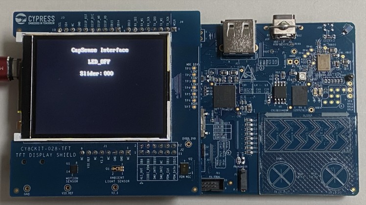
CapSense Interface
The CapSense interface does have a template application CapSense_Buttons_Slider that uses the 5-segment CapSense slider and the two CapSense buttons. Button 0 turns the LED ON, Button 1 turns the LED OFF and the slider controls the brightness of the LED. I've modified the code to display the LED state and the Slider value on the TFT.
Short video demonstrating slider and buttons
BLE Interface to iPad
There is also a template application to interface the CapSense slider and buttons to an iOS or Android application over BLE AnyCloud_BLE_CapSense_Buttons_and_Slider. This example is using FreeRTOS.
I am going to interface this with my iPad. I needed to install the CySmart app.
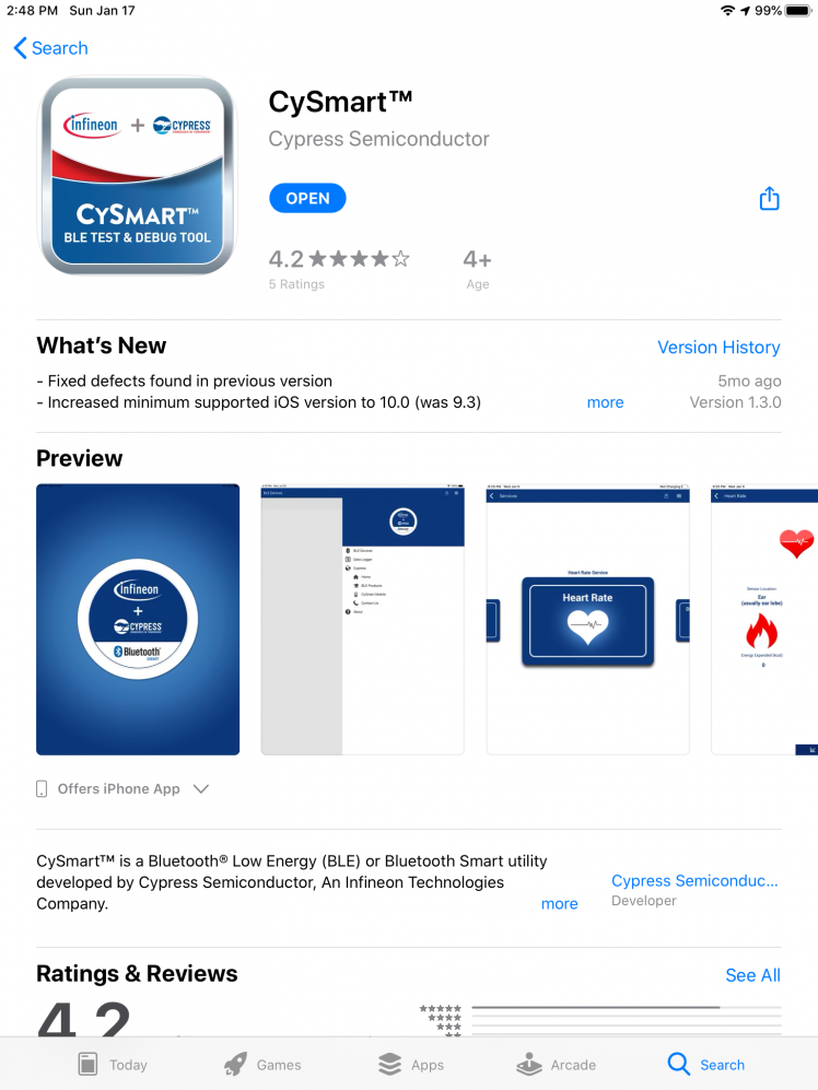
The program sends BLE advertisements for 90 seconds after it starts. In the CySmart app the CapSense Button Slider device will appear.
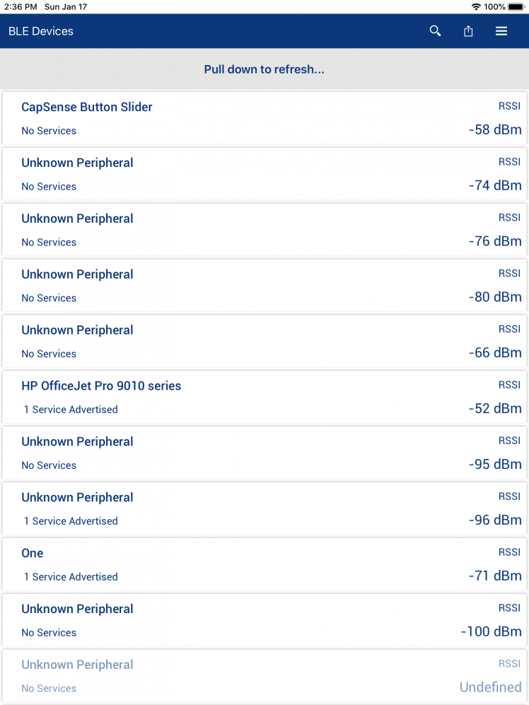
Selecting that device will connect to the CapSense Service

And selecting that service will show the Buttons and Slider Characteristics.
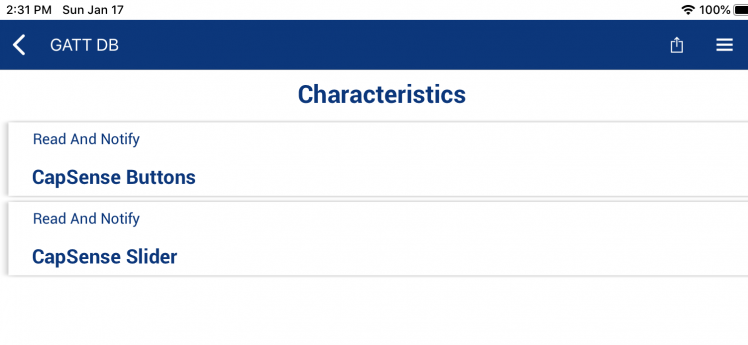
Here are some screencaps showing the Buttons and Slider Characteristics receiving values from the board.
PICSI Application
This application will utilize the features that have been tested previously. The purpose of the application is to provide a platform for evaluating IoT sensors.
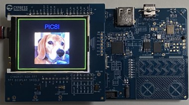
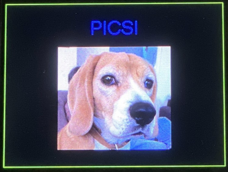
The interface is very basic. There is a Start Screen that displays the application name PICSI and a picture of my dog.
I use the CapSense interface to switch between screens. Button 0 selects the Start Screen. Button 1 selects the Sensor Selection screen which displays the choice of available sensors.
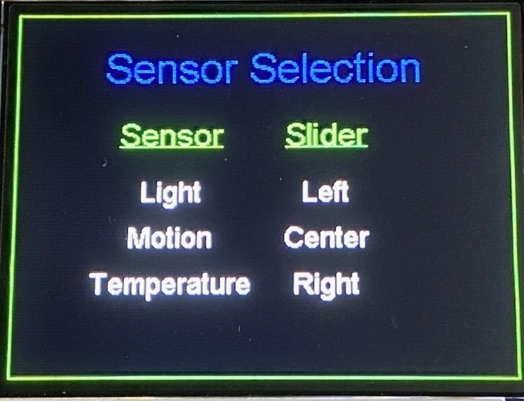
The CapSense Slider is used to select which sensor to display. For my demo I'm going to use 3 sensors, the ambient light and motion sensors on the Display shield and an external Grove NTC thermistor.
Light Sensor
The light sensor that is used on the TFT shield has a GitHub library that I included and example code. It is using ADC Channel 0 on Pin A0 (P10_0).
https://github.com/cypresssemiconductorco/sensor-light

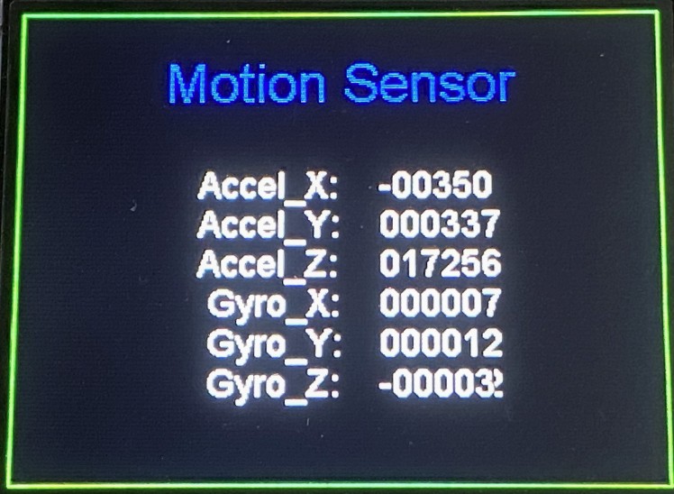
Motion Sensor
The BMI160 motion sensor used on the TFT shield also has a GitHub library and an example.
The only issue that I ran into is that this is an I2C sensor and it conflicted with the CapSense Tuner which also uses I2C. Rather than trying to configure another I2C bus, I just removed the code for the CapSense Tuner which I was no longer using.
https://github.com/cypresssemiconductorco/sensor-motion-bmi160/
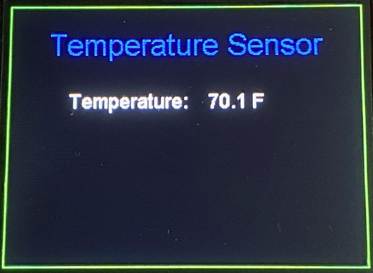
Temperature Sensor
For the temperature sensor I am using a Grove Temperature Sensor V1.2 which uses a buffered NTC thermistor https://wiki.seeedstudio.com/Grove-Temperature_Sensor_V1.2/

I am using ADC Channel 1 on pin P10_6 to read the voltage from the thermistor divider. I modified the example code from the Seeed Wiki to do the temperature readings.
I ran into a problem because the Light Sensor library configures the ADC in single channel mode, so I ended up not using the library and added the code for multichannel ADC and doing both the Light Sensor and Temperature Sensor value processing.
Program demo
Here is a short video to demo the program operation.
Final thoughts (Summary)
The PSoC 6 WiFi-BT Pioneer Kit is a great set of hardware to provide a base for IoT sensors. The Modus Toolbox is a nice software development platform that uses the Cypress PSoC 6 Hardware Abstraction Layer (HAL) to configure and use hardware blocks. It is a high-level interface that works well, but I encountered a few of problems using it. First, it does not provide the hardware coverage that was provided by the low level interfaces using PSoC Creator (e.g. you can't route GPIO other than Port 10 to the ADC using HAL). There are a lot fewer software examples using Modus Toolbox 2.2. I expect that this will change in time. Also, the software examples are not very modular, i.e. it's hard to use different sensor examples simultaneously without significant modification. That being said, the Community Support Forum is very helpful and responsive.
I did not end up interfacing as many sensors as I had planned because I ran out of time. I also hope to use TinyML with this kit in the future.
Code
Credits


Leave your feedback...