
Pipod

Made by electrouser955 / 3D Printing / Music / Sustainability
About the project
Raspberry Pi zero portable music player
Project info
Items used in this project
Hardware components


View all
Story
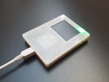
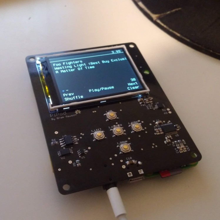
This is a portable music player based on a Raspberry Pi Zero. The first version was made using common modules this made it quite a mess, big and fragile. That's why I designed a PCB for it that has all the electronics on it. The music player interface uses VLC as the backend for playback and Pygame as frontend. The assembled PCB can be bought on Tindie.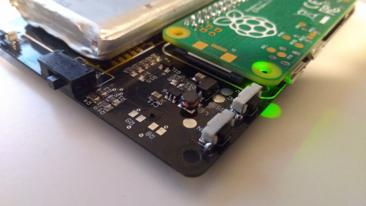

Details
Why did I build this?I made this music player because I wasn't satisfied with the current playback methods that are available. The music streaming services available started to feel like radio stations with the same music repeating, they are also depended on an online internet connection while there might be offline functionality it is still limited by the available storage on your phone.
Since most vinyl records come with a download code for MP3 files a dedicated portable music player with my own offline music collection seemed like a good option. Storage has become cheaper and cheaper in recent years so there should be a couple of music players with a lot of storage, right? Well, that's not the case, there are a couple of high-end players with enough storage, but these are a couple of hundred bucks. That's why I build the first version using parts I had laying around for a few bucks. Since then I've remade it a couple of times and I've finally come to a version that works completely and could be built for about €80, - including 64GB storage (depended on local pricing).
FeaturesDisplay
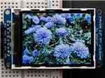
The display on this board has a resolution of 320 by 240 pixels with a screen diagonal of 2.2”. It is connected to the Raspberry Pi using the SPI bus.
I2S Audio outputThis board includes the PCM5102A a 24-bit I2S DAC with a 3.5mm jack. This IC is used to generate high-quality audio without a hum like you would get if you're using the onboard PWM as audio source.
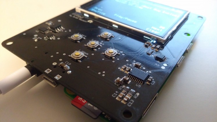
User controlsOn the board are controls for navigation, volume control and backlight control. There is also a slide switch on top to select between the USB output (off position) and battery output (on position).
Battery protection and chargingThe battery is charged using the TP4056 charger with a charge rate of 1000 mA. It is also protected by the DW01 battery protection circuit, this IC protects against: overcharge, overdischarge and overcurrent.
Battery monitoring and charging detectionBattery monitoring and charging detection are implemented using a ADS1015 ADC. The ADS1015 is a 12-bit ADC that is connected using I2C to the Raspberry Pi. Channel 0 is connected to the USB connection and channel 1 to the battery using a voltage divider, channels 3 and 4 are not being used but are broken out to two test pads next to the ADC.
Battery boosterThe nominal voltage of 3.7v outputted by the battery is converted to a steady 5v output by the MT3608 step-up converter. The MT3608 include under-voltage lockout, current limiting, and thermal overload protection.
Specifications- 1200 or 2000 mAh battery
- 2.2" TFT display
- 24-bit DAC (PCM5102A)
- Safe shutdown on low battery (not implemented yet)
- Navigation, volume and power buttons
- Music player interface
- Index music from
/Musicfolder - Sorting by artist, album and tracks
- Volume control
- Queueing
- Queue shuffling
- Sleep mode (Backlight off)
- Display artist name, album title and track title
- Index music from
Instructions
Bare board assembly
Recommended tools and supplies- Hot air reflow station
- Soldering iron
- Solder paste
- Flux pen
- Tweezers
Start by soldering the SMD components to the board using a hot air reflow station. The names on the silkscreen (images below) can be matched using the part list.
While placing the SMD components pay attention to the orientation of the MT3608(B6287z) and DW01 IC, below you can find pictures of the orientation.
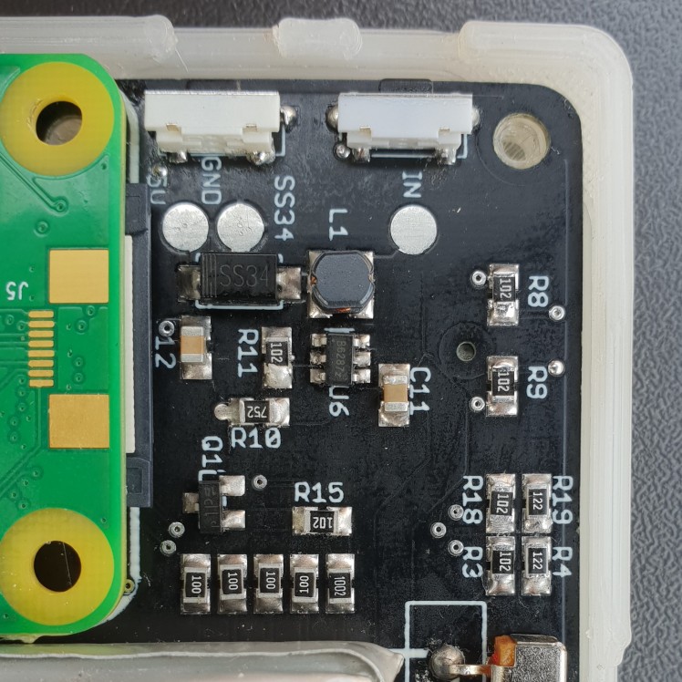 MT3608(B6287z)
 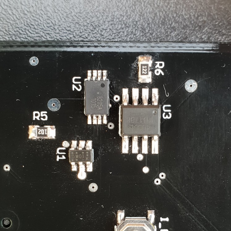 DW01 orientation
 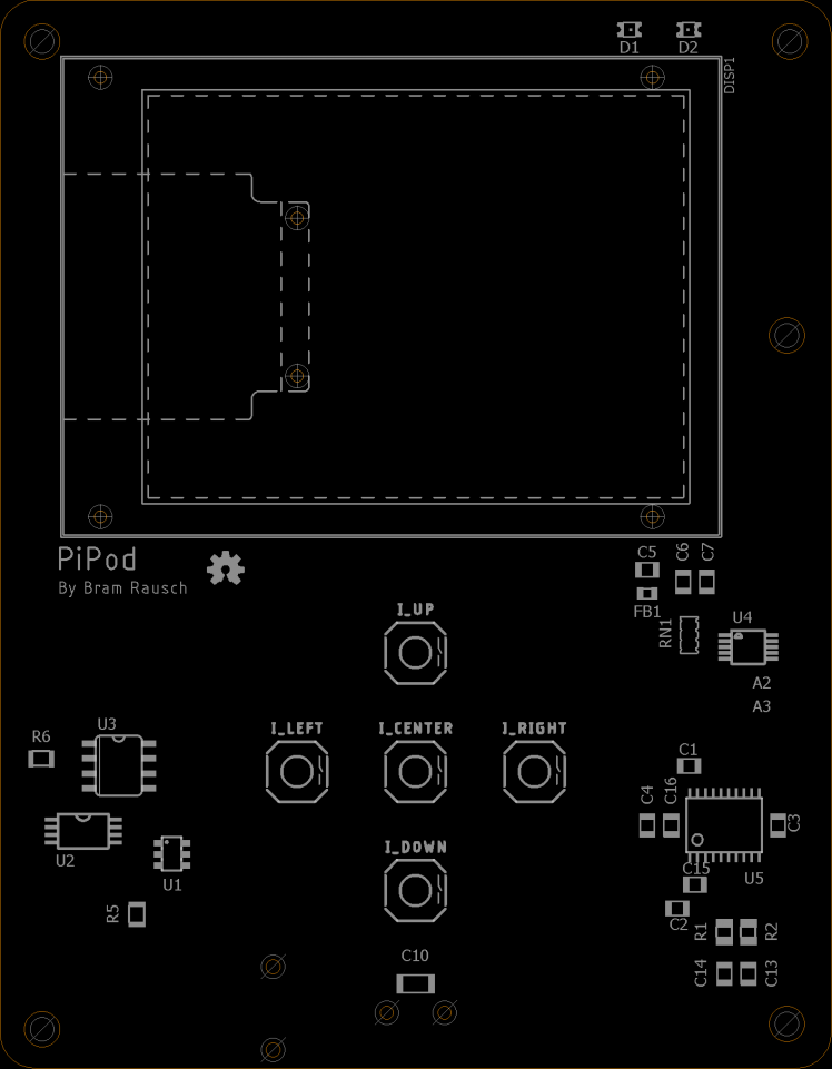 Silkscreen Top
 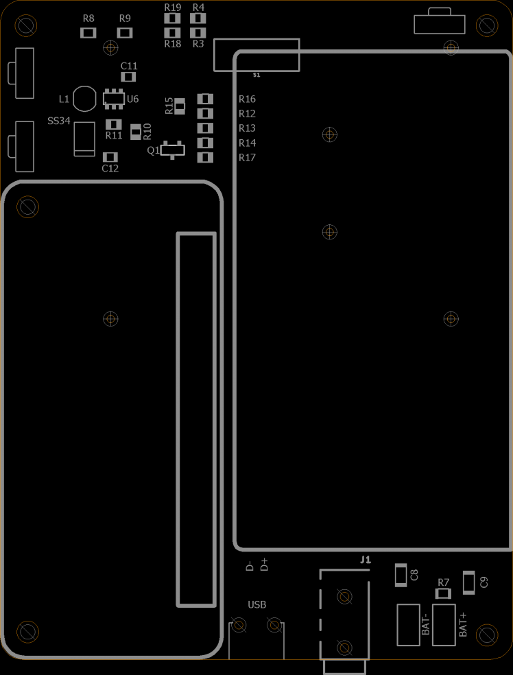 Silkscreen Bottom
Installation
Download the custom image here Initial setup:After you have downloaded the image and put it on your SD card boot up the PiPod and connect it to your PC.
- SSH into the PiPod:
- hostname: usbpi.local
- Username: pi
- Password: raspberry
- Expand the file system using raspi-config
- Shutdown the system and insert the SD card into your PC
- Put your music in the /home/pi/musicPlayer/Music folder
Use a FTP client(FileZilla) to connect to the PiPod and ut your music in the /home/pi/musicPlayer/Music folder.
- hostname: usbpi.local
- Username: pi
- Password: raspberry
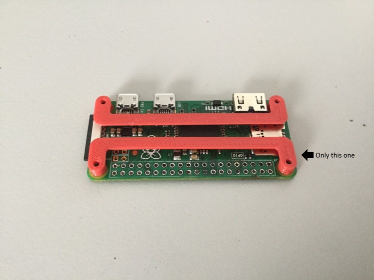
Aligning the Raspberry pi
Align and solder the Raspberry Pi to the PiPod board with the 3D printed spacers. These make sure that the RPi is spaced 4mm from the PiPod board to fit the case.
1. Get all the parts
- 4x m2 screws
- 1x RPi spacers
- 1x RPi zero
- 1x PiPod board
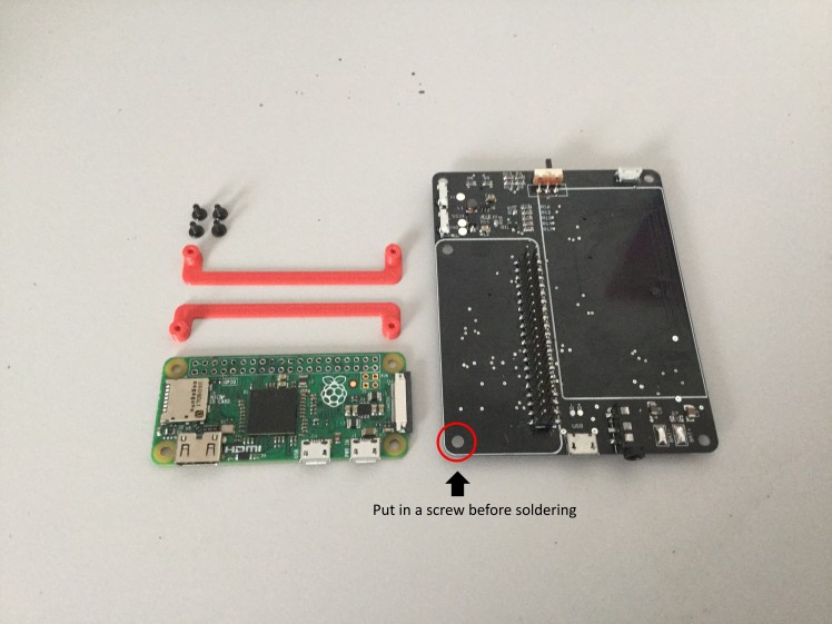
2. Put a screw in the hole that is circled red
3. Screw down the spacer
4. Align the edges of the two PCBs and solder down the RPi
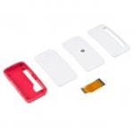
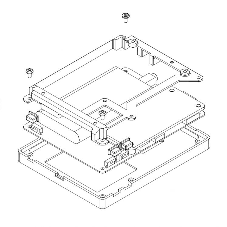
Case assembly
1. Place the top down
2. Put the navigation buttons in place
3. Put the PiPod board on top (make sure you've put in the screw between the RPi and PCB circled in red)
4. Put the side buttons in place and make sure they have a loose fit. If they are too tight you might want to file them down.
5 & 6. Put the frame on top and screw it in place, make sure you don't overtighten them.

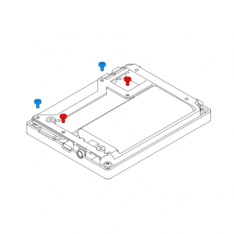
7a. Screw the frame into the RPi frame using the red screws.
7b. Place the printed rings under the RPi and screw down the blue screws.
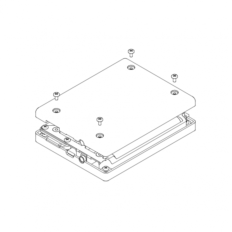
8. Solder the USB >
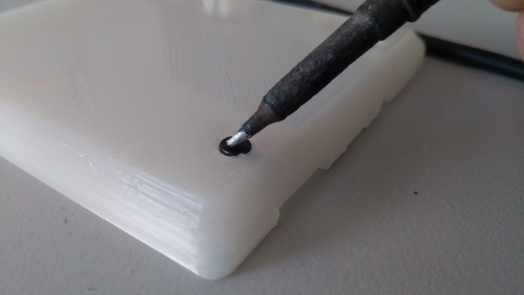
9. Before putting it all together remove the support from the countersunk holes. After the support has been removed use a screw and soldering iron to clean it up / make the top of the screw flush with the surface. Put the bottom part in place and test if the buttons aren't too tight. If this is the case file down the bottom part.
If everything fits nicely screw the part down.
Leave your feedback...