
Pcb Binary Watch

About the project
A PCB wristwatch that shows time in BCD binary form and the watch takes power from a coin cell battery. The watch is based on ATmega328P microcontroller and DS3231M RTC.
Project info
Difficulty: Difficult
Platforms: Arduino, Atmel, Maxim Integrated, JLCPCB
Estimated time: 3 hours
License: GNU General Public License, version 3 or later (GPL3+)
Items used in this project
Hardware components


View all
Story
Introduction
I love PCB. I love Binary. A few years ago when I was browsing the Instructables one project attracted me very much. The project was a PCB watch named The Nerd Watch. When I saw that I fall in love with the watch. I tried to make one but I didn't have all the tools to make the watch. After that several more PCB and Binary watches were made by community members and published on the Internet. Those watches are really excellent and mind-blowing. A few of them are:
MechWatch - a Custom Digital Watch
Taking inspiration from all of the watches above finally I made my own PCB Binary Watch which was my dream for many days.
I focused on the aesthetic of the PCB as I am going to keep it open from any type of casing. Intentionally I kept the trace of the top PCB layer free from solder musk so that all the track can be visualized clearly. That gives a better look. For preventing the tracks from corrosion I used Gold Finish on the top surface. I also placed all resistors and capacitors on the bottom side of the PCB.
After finishing I was surprised by the looking of the watch. It really looks great. This can be a perfect watch for electrical and computer engineers. If you are an engineer and like binary I am pretty sure you will like it.
This is going to be a perfect engineer's watch!!!
Watch the Video Below:
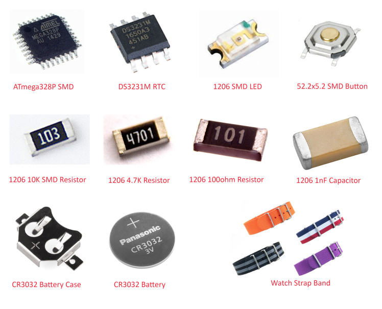
The Hardware Components
Making First Prototype
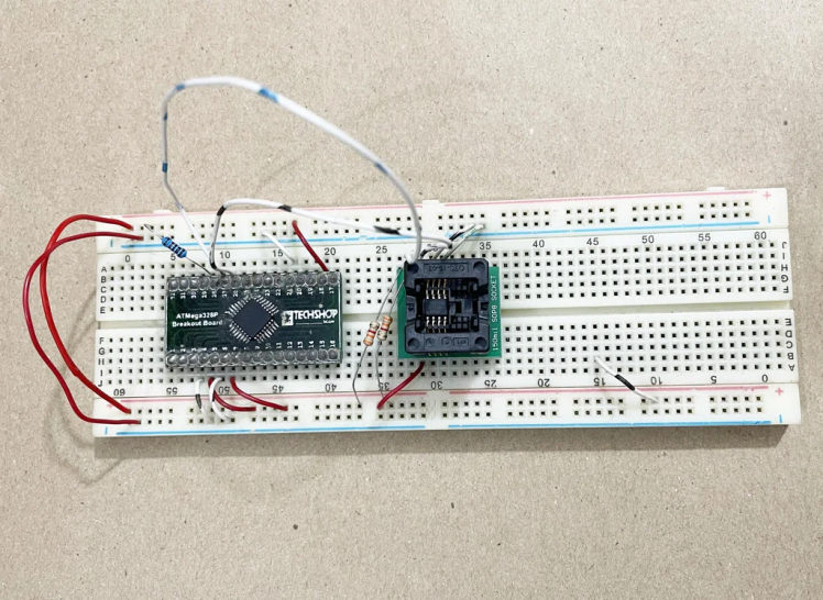
Before making the final PCB of any electronic product, it is very important to make a breadboard version of the product. This breadboard version will give you the information whether your final product is going to work perfectly or not. Most of the cases what we think theoretically may not work expectedly in the practical circuit. A Breadboard circuit is also helpful for developing the firmware of the circuit.
Before making this project I never used DS3231M SOP-8 RTC. I was not sure whether other RTC libraries like DS3231 will work or not with the SOP-8 package though it should work theoretically. So, it was very important for me to test my DS3231M with a standard RTC library before making the final circuit.
I had also another confusion about the TQFN package of the ATMEGA328P microcontroller. As I am going to design a wearable product and the device will be powered by a coin cell battery (CR2032) power consumption is a crucial factor of the project. Besides, for the aesthetic outlook, I was trying to keep the circuit as simple as possible to minimize the components and PCB traces. So, I had the intention to use the internal oscillator of the microcontroller without using an external one. For using an internal oscillator you need to change the default bootloader of the Arduino. So, I wanted to find which bootloader is going to serve my purpose. For all the above reasons I made a breadboard prototype before making the final PCB.
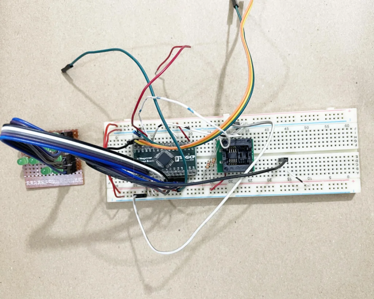
SMD ICs are not breadboard friendly. I used an SMD32 to DIP32 PCB board to place the SMD microcontroller on my breadboard. For the SOP-8 RTC I used SOP-8 to DIP-8 adapter. For displaying the binary time I used 13 LEDs and for developing and testing the firmware I made a LED display on the perf board.
For using the internal 8MHz oscillator I included the MCUdude board manager in the Arduino. The GitHub link of the board manager is: https://github.com/MCUdude/MiniCore. This board works for me without any problem.
For DS3231M SOP-8 RTC I used the following library. Link: https://github.com/Zanduino/DS3231M
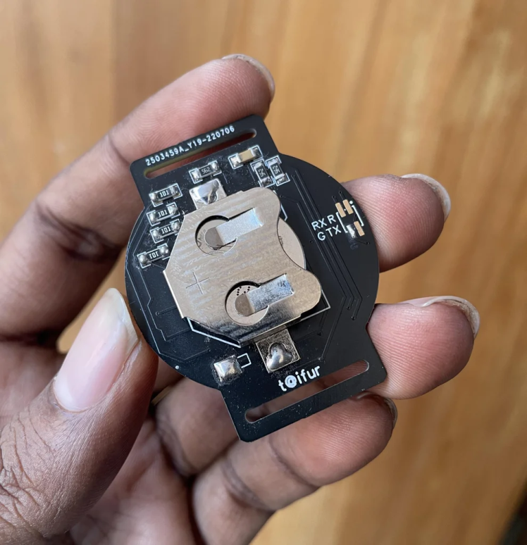
Power saving is one of the most important factors for a wearable device. I used a CR2032 coin cell battery for my project. This coin cell has around 200mAh capacity. So, we should utilize this battery very efficiently. I utilized the deep sleep functionality of Arduino and the device shows the time for only 10 seconds on every button press. Then it goes to deep sleep again to save the power. The button is connected to the external interrupt pin of the Atmega328P microcontroller.
You can download the low-power library from the link: https://github.com/rocketscream/Low-Power
The full Arduino sketch is provided in the Code section.
Designing Schematic & PCB
The Schematic
After successfully testing the prototype it is the right time to develop the schematic for the PCB. I generally used EasyEDA for PCB design because I easily find all the components required for my design and it has a rich set of the user-contributed library. The design work is also easy in EasyEDA. You can directly order the PCB from EasyEDA.
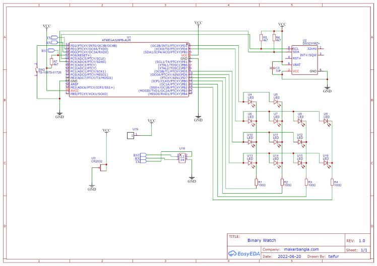
The circuit for the watch is very simple. A DS3231 is connected to the Atmega328P microcontroller using an I2C port. Two pull-up resistors are added to SCL and SDA lines. A 1nF capacitor is connected between the BAT and VCC line of the RTC as per the recommendation of the datasheet. A 10K resistor is connected to the VCC and the RESET line of the microcontroller. LEDs are connected in matrix form to save the pin of the microcontroller. Each common cathode is connected through a 100-ohm resistor. The size of the resistors and capacitors is 1206 as I am going to solder all the components by hand. Smaller components than 1206 are not suitable for manual soldering, especially for amateurs.
The PCB
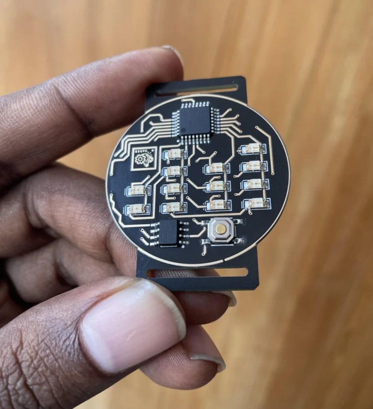
While designing the PCB I tried to make the top layer aesthetically nice and for this purpose, I placed all the resistors and capacitors on the bottom layer. The MCU is placed at the upper side of the top layer and the button and RTC are at the lower side of the top layer. LEDs are placed in the middle of the PCB.
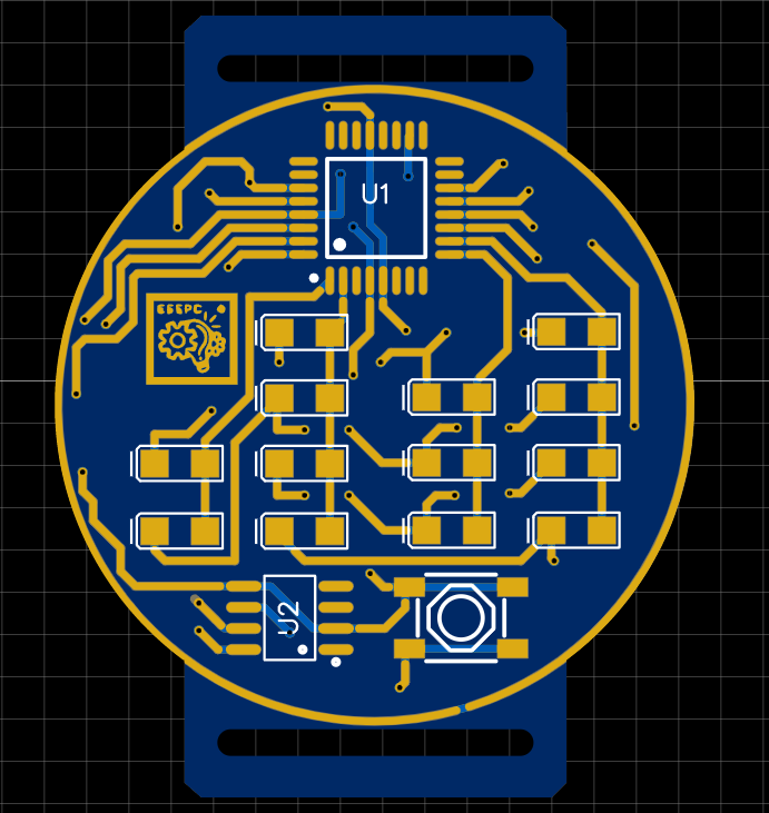
To bring a tech look to the PCB I have drawn the top traces very carefully. I want to use this watch without any casing or covering. That will give a more tech feeling while using the watch. To make the PCB traces more visible I kept the traces free from the solder mask. But without a solder mask, the traces will be affected by corrosion and oxidation. To protect the traces from corrosion I used a Gold Finish (ENIG) on the PCB. Of course, the ENIG finish is much more expensive than the traditional HASL finish but definitely it will give a more elegant look to the PCB.
Sending Design for PCB Manufacturing
After finishing the layout design it needs to be manufactured. JLCPCB provides excellent PCB manufacturing services for hobbyists and professionals. I always use JLC PCB for my personal PCB-related project because they provide good quality PCB at an affordable price. The delivery is also fast.
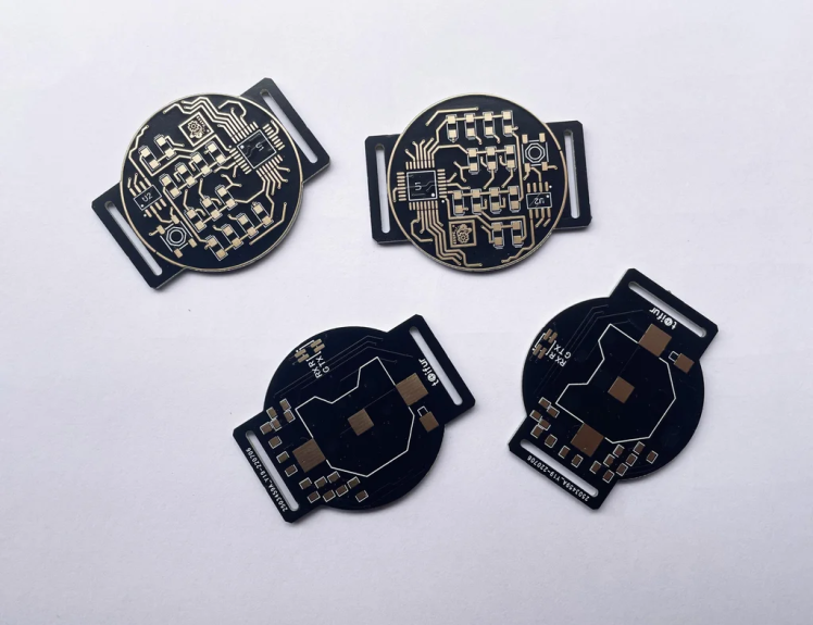
Ordering PCB in JLCPCB is very easy. You can directly order from the EasyEDA platform or you can order by downloading the Gerber file from EasyEDA with just a single click. You can choose your favorite PCB color from plenty of options.
I ordered black colored PCB with Gold (ENIG) finish. Don't forget to order a stencil with the PCB. It is very important for adding the right amount of solder paste to the PCB and you will get a professional solder joint and a professional look.
Placing the Components
The outlook of the watch face is very important and you will not get good finishing if you solder SMD components using a soldering iron. Hot air is a better option but components alignment may be hampered by the air flow. The best way is to use a reflow oven or reflow hot plate. Either you use a hot air gun or a reflow oven in both cases first you need to apply solder paste before placing the components. The best way to apply the right amount of solder paste is to use PCB stencil which you may order with the PCB. For applying solder paste the stencil must be perfectly aligned with the pads of the PCB. You may use adhesive tape to temporarily fix the stencil with the PCB after successfully aligning with the pads. Then you may use a credit card or something like it to apply the paste on the PCB.
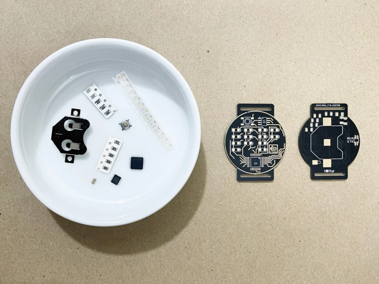
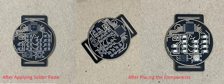
After applying the solder paste and removing the stencil you need to place the components by using a tweezer. The final outlook will be as nice as perfectly you can place the components. So be careful and patient while placing the components.
Soldering With Reflow Hot Plate
As I already said the perfect SMD soldering can be performed only with a reflow oven or reflow hot plate. You can buy a reflow oven from aliexpress.com or amazon.com or you can make a reflow oven from a toaster oven.
Similarly, you can buy a reflow hot plate from aliexpress.com or you can make one by yourself. I made a reflow plate by myself and I used that reflow hot plate for soldering my watch PCB. Some good sources on the topic are:
This is a guide on soldering reflow profiles you should know if you like to make one by yourself.
Watch my reflow video on the soldering of my PCB using my self-made reflow plate.
I am surprisingly happy by getting the excellent result from my reflow plate.
My watch PCB is a two-layer PCB. But soldering both the top and bottom layers using a reflow hot plate is not possible. So, I used a soldering iron to solder the bottom components.
Watch the Reflow Video attached at the beginning of the section.
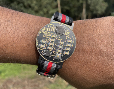
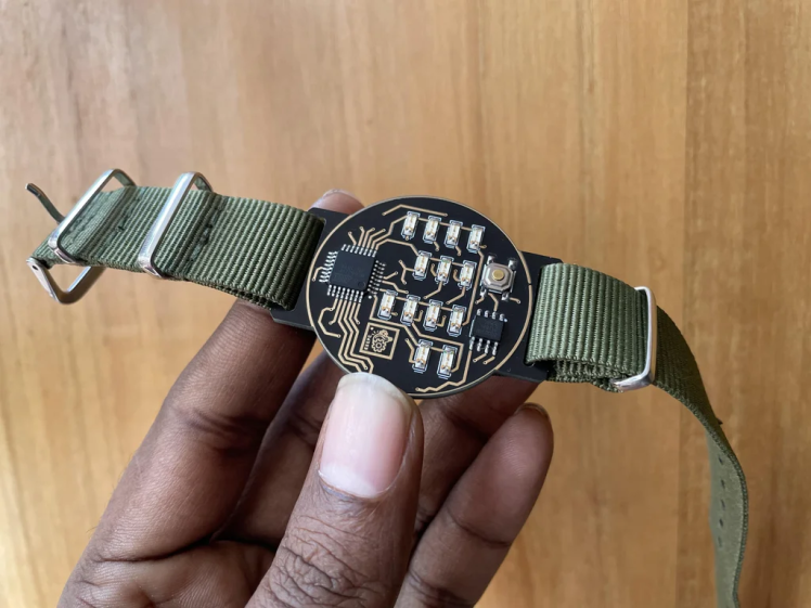
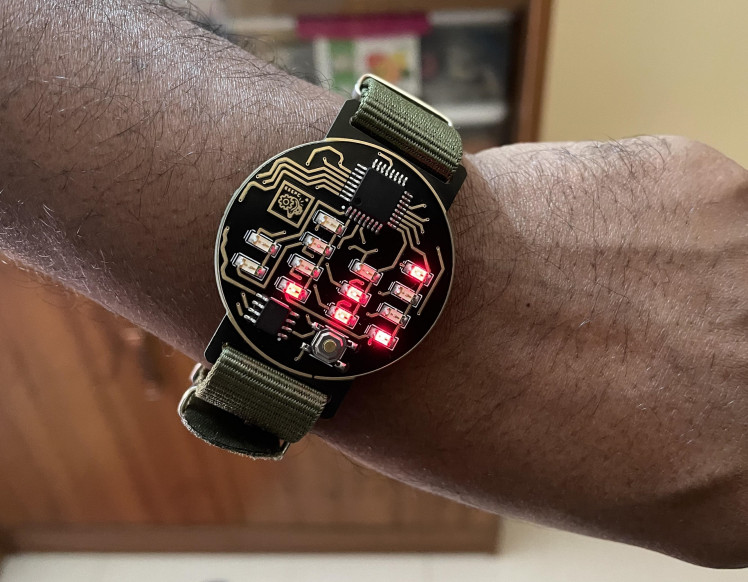
The Finished Watch
After completing all the steps above your watch is now completed. You can attach a watch strap and wear the watch. I used a NANO strap for my watch because it is very easy to attach to the watch and looks nice.
How to see the time:
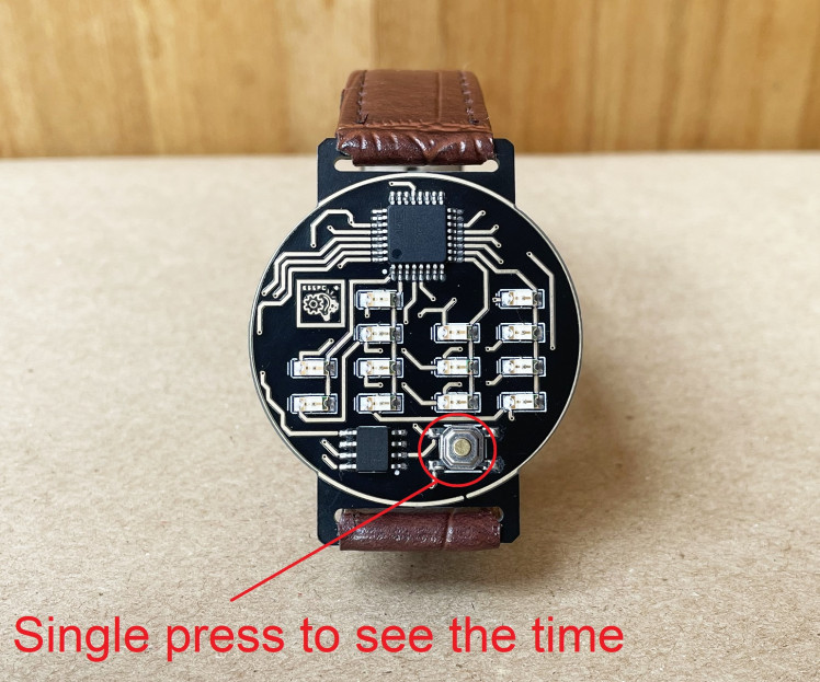
For saving power the device spends most of the time in sleep mode. To see the time just press the button once, immediately it will display the time in binary form for 10 seconds. Then it will go to sleep mode again.
How to read the time:
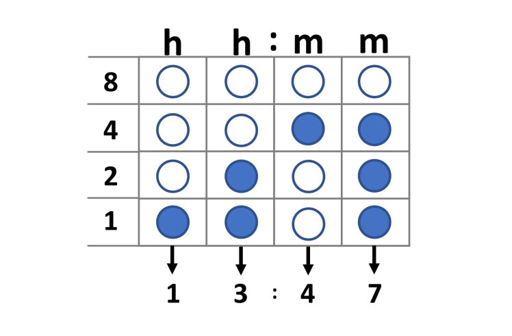
Reading time is easy for engineers. The binary watch would operate just like a regular watch except that the interface would be binary, specifically, BCD (Binary Coded Decimal). BCD is a type of binary encoding where each decimal digit is represented by a fixed number of bits. I need 4 bits to be able to represent a digit from 0-9. And for a standard hh:mm time format, I need 4 of those digits. This means that I need a total of 16 bits which will be represented by 16 LEDs.
Reading the time in BCD is pretty easy once you get used to it. The row at the bottom of the watch represents the least significant bit (1) and the row at the top is the most significant bit (8). Each column represents a digit in the hh:mm time format. If an LED is ON, you count that value. If an LED is OFF, you ignore it.
To read the first digit simply sum all the activated LEDs corresponding values in the first (left most) column. Do the same for the other digits from left to right. You have now read the time in BCD!
Guess the time:
You are right! It is 1:39.
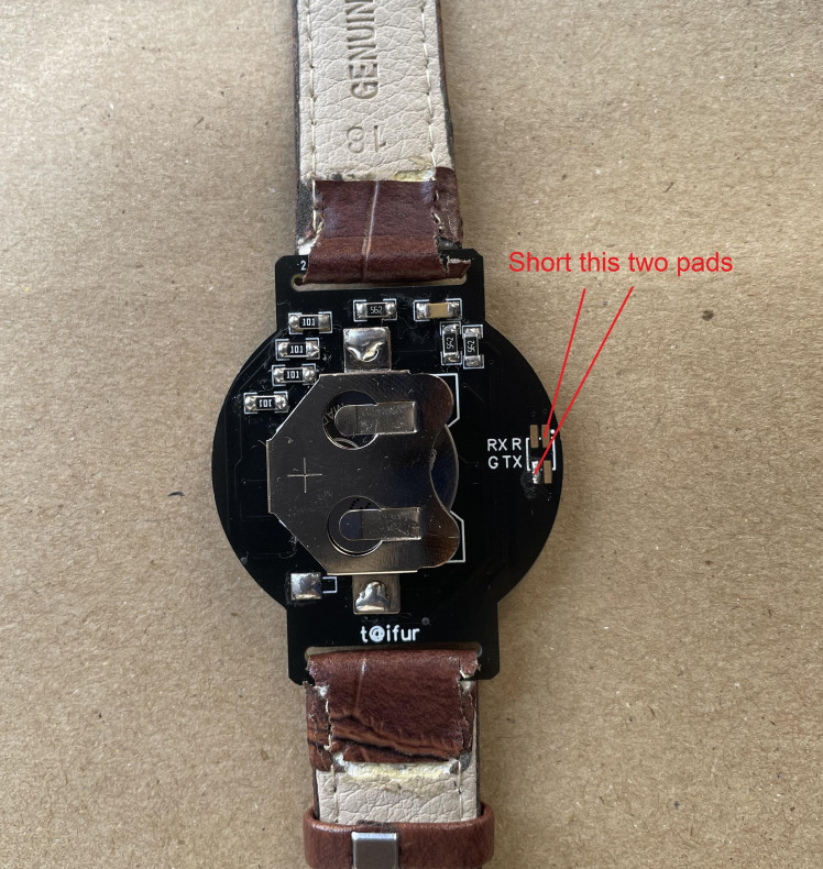
How to adjust the time:
There is no time adjustment button on the watch. You have to apply a single trick to set the time. The watch starts its time from 12 PM on power up or reset. So, when you need to replace the battery just insert the battery at exactly 12 PM. The time will start from 12 PM.
Alternatively, you can adjust the time by shorting Reset and Ground pads from the bottom side of the clock PCB.
How long it will survive with a single battery:
I don't have any calculations on power consumption, so it is tough for me to tell how long it will run with a single coin cell. But I am using this for more than a month with a single coin cell with an average of 5 presses per day.
Schematics, diagrams and documents
Code
Credits
Related products


Leave your feedback...