
Ocean Buoy to Measure Waves & Drift using Low-Power Cellular

Made by gaute-hope
About the project
A small and low-cost drifter and wave-measuring buoy for the Ocean close to the shore and inside fjords.
Project info
Difficulty: Moderate
Platforms: Adafruit, SparkFun, STMicroelectronics, Blues Wireless
Estimated time: 1 hour
License: MIT license (MIT)
Items used in this project
Hardware components

View all
Story
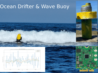
A small and low-cost drifter and wave-measuring buoy for the Ocean close to the shore and inside fjords. A buoy that can measure ocean waves at a high enough frequency (50 Hz) to study breaking waves. And that can transmit relatively large amounts of wave measurements and drift trajectories back to a server at short intervals. The buoy is also a useful starting point if you wish to transmit other types of data from the ocean. The data is also (optionally) stored on an SD card and can be requested later if the buoy has been without cell service.
Assembled and sealed up buoy, spray-painted so that it is easier to spot in the ocean.

Assembled and sealed up buoy, spray-painted so that it is easier to spot in the ocean.
Motivation
Inside fjords and close to the shore is where most incidents happen, whether environmental or boats or people in distress. Additionally, those are the most challenging areas for ocean and weather models to simulate and forecast weather. The resolution of operational forecasting is also much greater than the scale of the narrow sounds, islands and often fjords.
Breaking waves are extremely difficult to study, and also very interesting for surfers. These buoys have been deployed by surfers in the breaking waves in order to study the waves as they start breaking towards the shore.
You could also put this device on a boat or something else and measure its movement, or track its drift.
Assemblyhttps://github.com/gauteh/sfy/tree/main/hardware

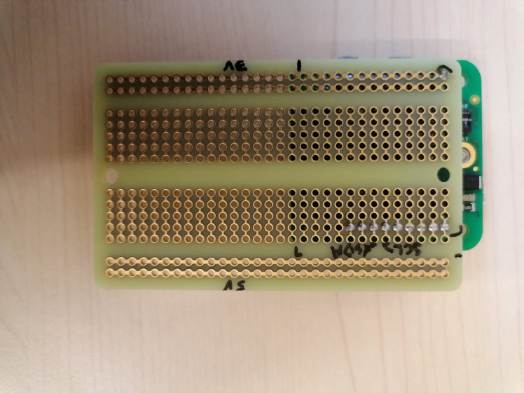
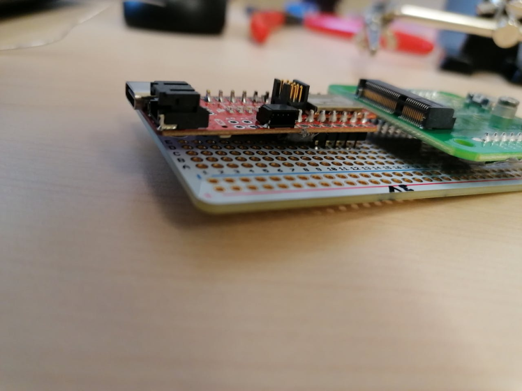
We assemble the components on a half-size protoboard. It is a bit crammed, so if you are not using a small bottle or enclosure you will have an easier time with a larger protoboard. Take care when prototyping on breadboards, since the connections and wires are often so poor that they will interfere with power supply and data-signals.
Make sure you align the components onto the protoboard before you start so that you see what fits, and in what order you need to solder components and jumper wires.
Start by preparing the components, and soldering headers on to the Artemis (make sure you use the innermost string of pinholes):
Artemis with headers soldered onto the innermost holes.

Artemis with headers soldered onto the innermost holes.
If you use a passive GPS antenna remove the 0 Ohm resistor according to the blues specification:
Carefully removing the 0Ohm resistor since we are using a passive GPS antenna.

Carefully removing the 0Ohm resistor since we are using a passive GPS antenna.
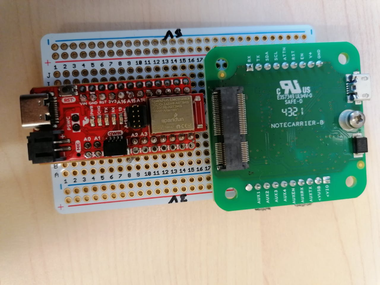
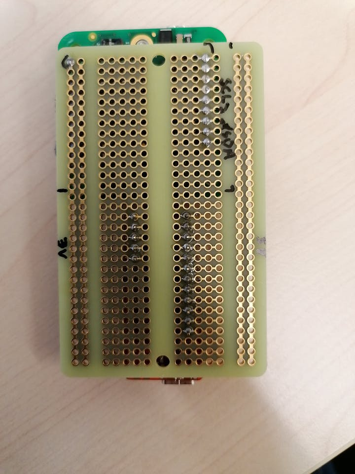
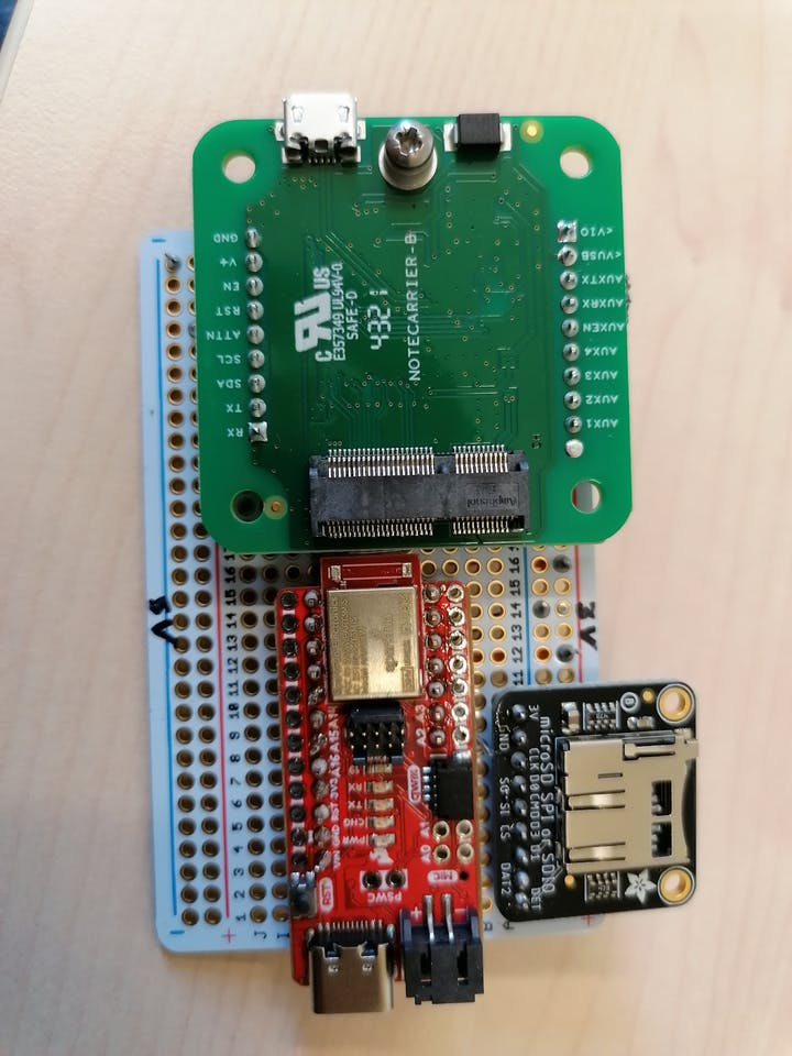
Since the Artemis and the IMU require very little power we will use the reference power from the Notecarrier-B (VIO) to power them. Note that this might change in future versions of the Notecarrier-B. The Notecarrier-B is actually a bit too wide for the standard breadboard (maybe something for Blues to consider in the future?). The Notecarrier should be aligned with the USB port out, and the VIO pin on the outermost + rail (make sure to rotate the protoboard so that the VIO + rail is outermost and not second-outermost). Mark this power-rail with 3V3. Mark the other power-rail with 5V. Connect grounds between the two with a jumper wire.
Before soldering on the Notecarrier all the pins, except VIO, on the VIO side should be cut, so that they are not connected to 3V3. Check also that the switch on the notecarrier is on 3V3.
This will prevent you from attaching to AUXTX/AUXRX for debuggingthe Notecard, but you can still use the USB for debugging (it will interfere with the power though).
Pins except VIO removed from one side of the Notecarrier-B.

Pins except VIO removed from one side of the Notecarrier-B.
If you want to power the whole buoy from your computer while debugging or programming, without using batteries or a power-supply, you can connect the Notecarrier USB to your computer. The rest of the device will be powered through the Notecarrier.
When the Notecarrier-B is aligned as it should on the protoboard, mark the positions of the SDA and SCL pins, and notice where the pins go in so that you don’t add jumper-wires there. It might be useful to solder the jumper-wires before you solder the Notecarrier on, but it is possible to solder them on the other side of the proto-board.
Make sure that there is enough space between the cut pins and the board that they do not connect.
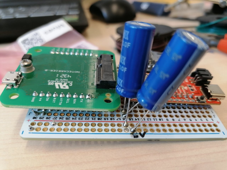
First, cut the A2 and A3 pins on the Artemis to avoid connection with the SD card. The Artemis goes on the other end of the protoboard, with USB port outwards (opposite direction of Notecarrier USB port). Make sure you leave free spots for the super-caps to be hooked up in series over the 5V rail.
Connect the SDA and SCL from the Notecard to the Artemis.
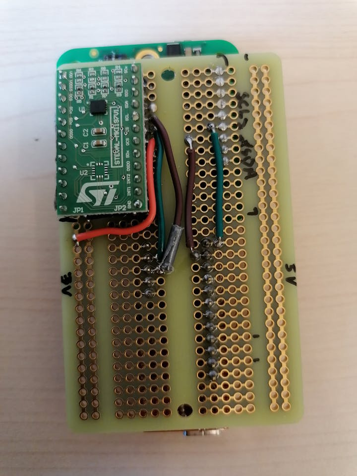
Next, prepare the IMU for mounting on the underside of the protoboard.
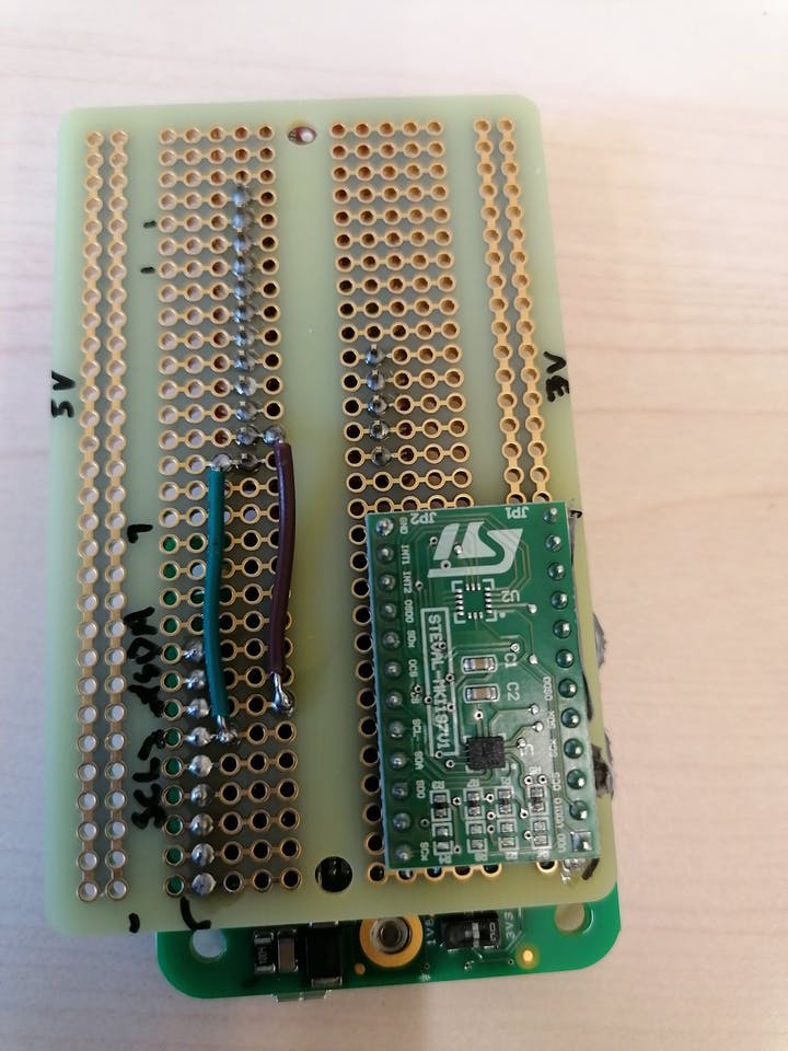
There are four pins on the VDD-side (right-hand) that are connected to the 3V3 rail. Cut the unconnected pins on that side, and leave the other (left-hand) side intact. Depending on whether you put the jumper-wires under the IMU or on the outside, solder the IMU before or after the wires. It is advised to solder the two GND wires under the IMU, as the board will soon be crowded. Refer to the schematic for how to hook it up to the Artemis and to 3V3 and GND. Here we are using the STEVAL board with the LSM6DSOX. Note that if you are using the ISM330DHCX board from Adafruit, the SDA and SCL pin-outs are swapped on the board, so debug on a breadboard first to make sure you hook them up right.
Unconnected pins removed so that the remaining pins can be placed in the 3V3 positive rail.

Unconnected pins removed so that the remaining pins can be placed in the 3V3 positive rail.
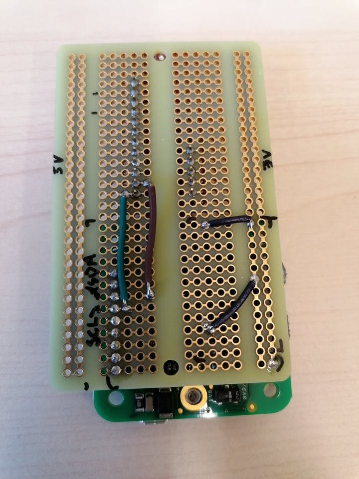
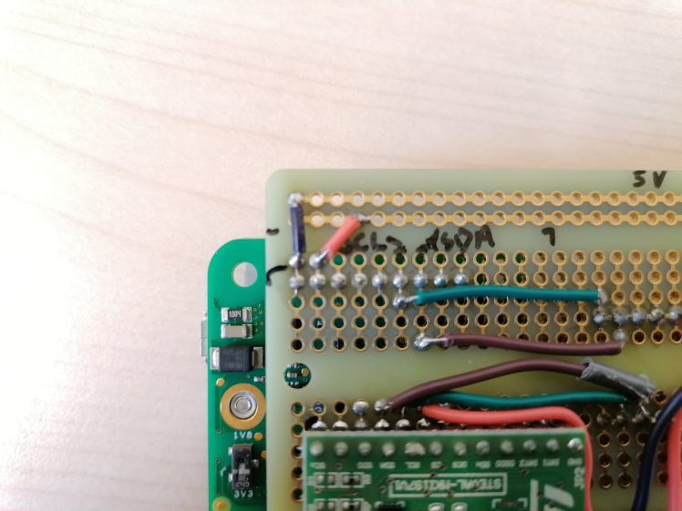
Then, place the SD card board on the protoboard. Wire up the power for the Artemis from the 3V3 rail to the +3V pin of the Artemis, as well as ground by going around it. Then, wire up the two grounds of the board together.
Then hook it up to the Artemis by following the schematic.
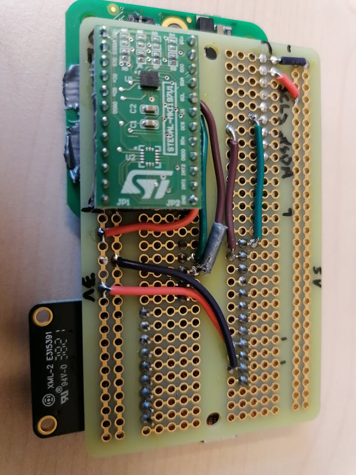
Finally hook up the super-caps in series over the +5V rail. And connect power from +5V and GND to the Notecarrier. It is especially important that the power loop over super-caps, and Notecarrier power-supply is low-resistance, soldered and with short cables. Otherwise the current-draw (up to 2A spikes) when the Notecarrier connects to the GSM network will cause significant voltage differences.
Attach a power-cable and connector of choice with suitable battery-packs. We preferred Alkaline batteries since mixing Lithium batteries with ocean water can be dangerous (although not uncommon). With 2x3 C-cells of high quality batteries (7800 mAh) you get about 14 days of continuous logging at 50 Hz. Look for high-capacity batteries that can support high-drain devices.
If you need an on-off button you can put it between the Notecarrier EN and GND, open-circuit is on. Sometimes when connecting power with batteries that can’t supply enough power, charging the super-caps will take so long that some of the components can be stuck in a brown-out state (in-particular the IMU).
Setting up the Rust environmentThe firmware and the data-server is programmed in Rust. Rust has an active embedded community with great resources: https://www.rust-lang.org/what/embedded. We need the toolchains for your host architecture and for the ARM target of the Artemis. There is a Dockerfile with a Ubuntu environment set up for compiling firmware and data-server in the repository. Alternatively you set it up yourself. The instructions will vary a bit depending on your environment, but on a Ubuntu 20 machine it goes something like this:
Install Rust nightly using e.g. rustup (2022-03-21 is known to work):
$ curl https://sh.rustup.rs -sSf | sh -s -- --default-toolchain nightlyOn Ubuntu you need at least the following dependencies:
$ apt install gcc-arm-none-eabi binutils-arm-none-eabi libclang-common-6.0-dev clang-6.0 libclang-devWe also need the additional rust compiler targets and tools:
$ cargo install cargo-binutils
$ rustup target add thumbv7em-none-eabihf
$ rustup component add llvm-tools-preview
There are many resources on how to get started with Rust, but it’s good to know that cargo is the package manager and build system for Rust, which we will be using. If you have a hardware debugger, there is built-in support for it through probe-run (with patches), or you can use gdb to load the firmware. Otherwise you can load the firmware over USB using Sparkfun utilities.
Source code and firmwarehttps://github.com/gauteh/sfy/tree/main/sfy-buoy
Get the source code with submodules using:
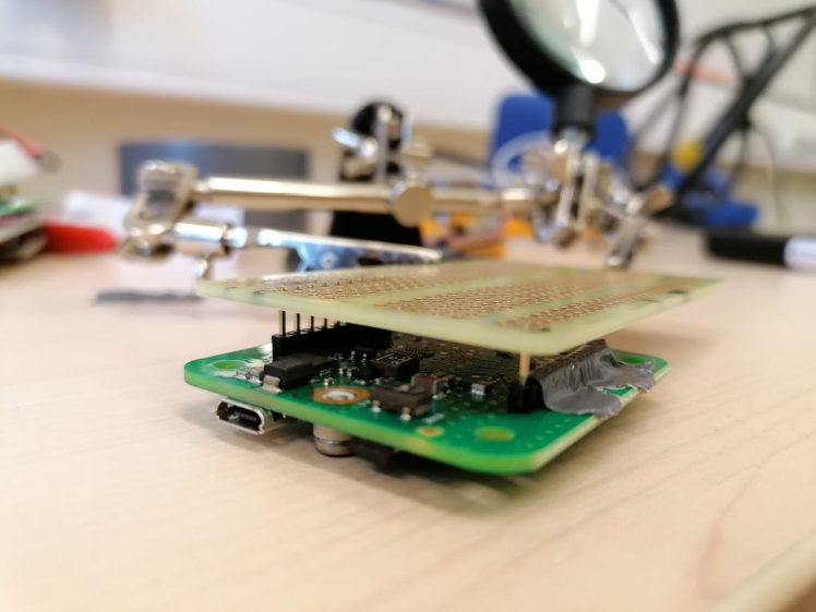
$ git clone --recursive https://github.com/gauteh/sfy.gitThe firmware is located in the subfolder `sfy-buoy`. The source code is written in Rust and can be flashed using the USB cable with the standard Sparkfun Variable Loader, or with a debugger. It is fiddly to mount a debug header to the Artemis, but you can often get away by just holding it in place in a tilted position.
The default configuration logs at 50 Hz and transmits data every 20 minutes. But you can configure it to transmit continuously at the cost of higher battery consumption. The battery consumption is largely proportional to the frequency of transmission. So by lowering the sample rate, the buffers will fill up slower and it is not necessary to transmit that often.
The FIR filter is tuned to 50Hz sample rate, so if you reduce the sample rate the filter needs to be updated. Its coefficients are calculated with a simple python-script (available in the source code).
You need to define a couple of environment variables:
BUOYSN: A human friendly name for the buoy.
BUOYPR: The account and product that you set up on notehub, so that the data ends up in your account.
DEFMT_LOG: If you use a debugger you can get detailed deferred logging here.
In case of panics or crashes the buoy will try to log the exception details to the Notecarrier before rebooting. Since the BUOYPR needs to be configured it is a bit tricky to provide pre-compiled binaries, but we hope to find a way to do that.
Refer to the READMEof the firmware for the most updated information on feature flags, e.g.: deploy, which avoids busy-waiting in the main-loop.
Before starting the firmware make sure you register an account on notehub.ioand create a project.Refer to the section below or Blues tutorials.
You can run the following to build the default configuration of the firmware (replacing BUOYPR with your email and chosen project):
$ BUOYSN=WAVEBUG01 BUOYPR=com.emailserver.user:sfy cargo objcopy --release -- -O binary target/sfy-buoy.binTo upload the firmware, hook the Artemis up with USB and (replace with correct port, install any missing python dependencies):
$ python3 ../tools/svl/svl.py -f target/sfy-buoy.bin /dev/ttyUSB0 -vThere are many other ways of accomplishing this, but this is the one that requires the least tools. There is also a Makefile where you can do to accomplish the same:
$ BUOYSN=wavebug01 BUOYPR=com.emailserver.user:sfy make flashThe data is sent by the modem to the blues.io Notehub server. You could either write a script to fetch the data from there, or set up a data-server that you route the data to. We did the latter. The processing scripts can either read files you have fetched yourself, or communicate with the data-server to get the latest data.
The data server is found here: https://github.com/gauteh/sfy/tree/main/sfy-data. The server can be configured in the sfy-data.toml file to set the read-only token, and the read-write token that you need to use at notehub.io when setting up the data-route.
To build the data-server enter the sfy-data directory and build and run it with:
$ cargo run --releaseOr install it with:
$ cargo install --path . # now run with `sfy-data` commandThe server stores all the received JSON messages in a SQLite database. With a read-only token those can be accessed from the processing software or a web application.
To receive data you set up an account at notehub.io and register a project. This project and account is necessary to provide to the buoy-firmware when you compile it, so that notehub.io knows which device to associate with your project. The notehub.io interface is very useful for watching the health of the device: logs, voltage, data coming in - and also importantly updating the firmware of the notecard. The required notecard firmware version is 3.2 or greater.
Blues has a tutorial for routing the data to either our custom data server or somewhere else: https://dev.blues.io/guides-and-tutorials/routing-data-to-cloud/general-http-https/.
There is a basic web-interface for looking at the last positions of the buoys, but at the time of writing it is not very useful: https://github.com/gauteh/sfy/tree/main/sfy-dashboard.
Visualization and Datahttps://github.com/gauteh/sfy/tree/main/sfy-processing
There are some processing tools for downloading and viewing the data in the sfy-processing/ sub-directory. You can set up the server host address and read-token in the environment, or in a .env file corresponding to where you started the server above. An alternative would be to set up a system for scraping the data from notehub.io before the events are purged. If you do that, let us know!
Using conda to set up the environment:
$ conda env create -f environment.yml
$ conda activate sfy
$ cd sfy-processing/
$ pip install -e .
Set up the .env file:
SFY_DATA_SERVER=http:///
SFY_READ_TOKEN=secret
SFY_DATA_CACHE=/path/to/local/cache
And try and get a list of devices and data using:
$ sfydata list
$ sfydata list [buoyname or modem id]
$ sfydata axl file [buoyname] [filename from previous list]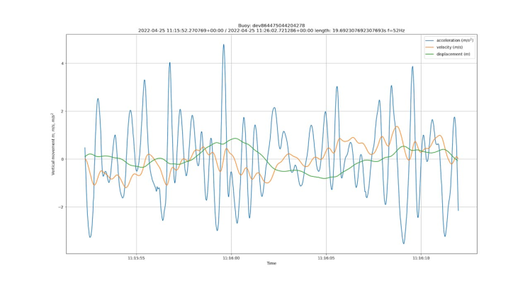
Waves measured in breaking waves.

Add a normally-open magnetic reed switch between Notecarrier-B EN and GND (in schema).
- Add a normally-open magnetic reed switch between Notecarrier-B EN and GND (in schema).
A better antenna or better mounted antenna—we’re testing out different options.
- A better antenna or better mounted antenna—we’re testing out different options.
This work is based on theOpenMetBuoy-v2021a, seeRabault et. al. (2022).
Schematics, diagrams and documents
Code
Credits
Related products


Leave your feedback...