
Nest Your Old Thermostat Under $5

Made by NotEnoughTech / Home Automation / Sensors / Voice
About the project
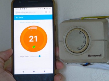
Make your old thermostat smart again with this $5 device!
Project info
Difficulty: Moderate
Estimated time: 2 hours
License: Creative Commons Attribution CC BY version 4.0 or later (CC BY 4+)
Items used in this project
Hardware components


Story
The heating system in my house is probably as old as the house itself. It’s about 30 years old, which is fine in terms of house years, but pretty much stuck in the ice-age as far as the technology is concerned. For some time now, I wanted to add the “smart” controls to the heating in the house. I have a timer, which can be programmed and the wall-mounted old Honeywell thermostat which can override the timer based on detected temperature. I also have similarly aged wife, who is not keen on me messing about with heating during the cold winter months.
Features:
- Temperature controls (duh)
- Alexa support
- Away mode
- Old thermostat can be still used
- Remote access
Planned:
- ⌛Google Home, Google Calendar integration
- ✅HTTP requests
- ✅ Amazon Dash support
- ⌛IFTTT
- ⌛Less scary enclosure with LCD and slider or rotary encoder
- ⌛Protection against heating oscillation
- ⌛Taking temperature readings from multiple sources
- ⌛Controlling WiFi radiator valves
Making your old thermostat smart again!
The thermostat is likely connected to the ⚡️HIGH VOLTAGE!⚡️ Do not attempt to do anything unless you made sure the circuit is off. You can harm yourself and cause damage to the connected equipment. Consider consulting a qualified electrician to assure your safety.
The permission has been granted let’s get to work before she changes her mind.
How do thermostats work?
The Honeywell thermostat is a wall mounted unit, powered by the mains (Sonoff basics need min 90V, my circuit has 230V). The box is connected to the main controlling unit (which is a more advanced box) and it sends the signal when the temperature drops below the target level. While your unit may be different, the principle is most likely the same. If you have 3 wires and no radio connection between the wall-mounted unit – this is the tutorial for you.
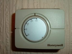
I know how the 3-wire thermostats work in a principle, which didn’t stop me from blowing a fuse by shorting 2 wires by accident! I have 3 wires connected to the unit (with 4th being the earth). My Honeywell thermostat is not wireless, so to switch the signal, I can use Sonoff Basic. It’s time to take it apart and see how the signal is sent to the unit.

Upon closer inspection, the terminal is connected in the following way:
- (blue) – Ground
- (yellow) – signal, when pulled high the heating is on
- not in use
- (red) – the live wire used to pull the signal high
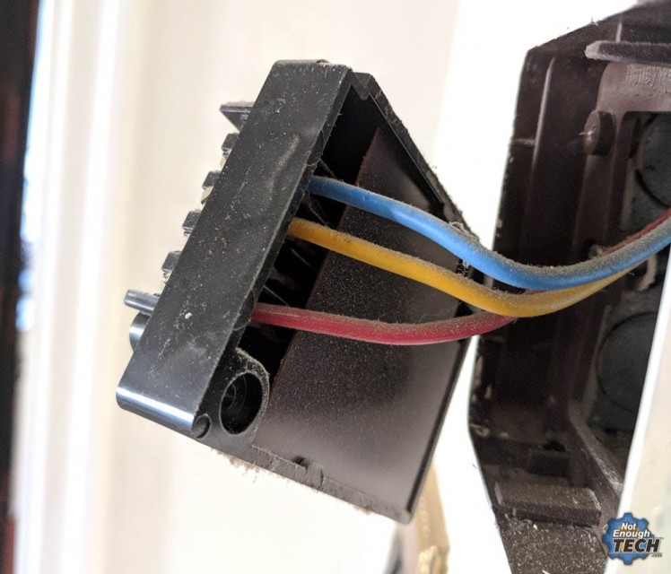
To achieve my goal, I have to short the live wire with the signal wire when I want my heating to be turned on. If you have a similarly connected thermostat, you are in luck as Sonoff Basic will be enough to do the trick.
Sonoff Basic – is all you need!
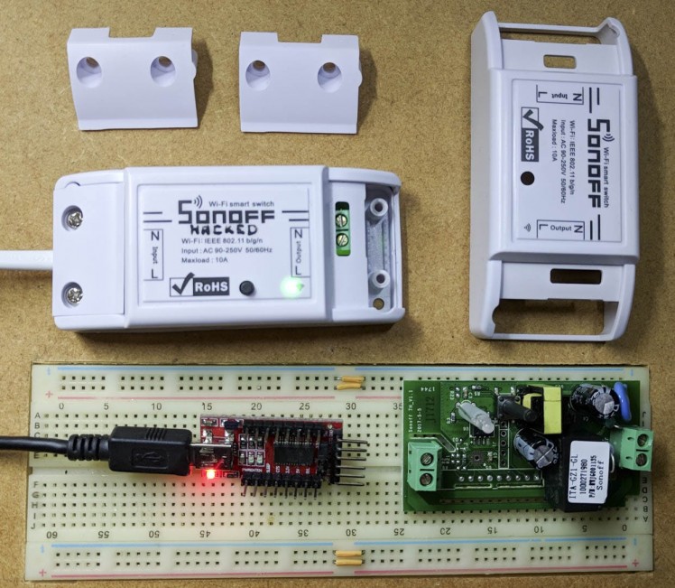
Before we start connecting the wires, we have to add a temperature sensor (DHT11) to the mix. Make sure you have Tasmota firmware flashed to your Sonoff device (I have an excellent flashing guide here) and your Tasmota-enabled Sonoff is configured correctly (also already covered by me). Now, all you have left is to connect the DHT11 sensor to the Sonoff and configure it for temperature reporting.
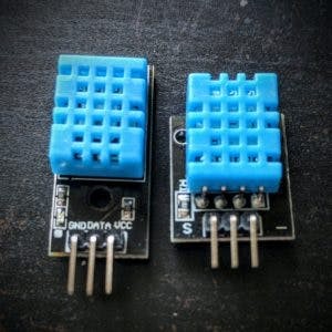
DHT11 comes with 3 pins wired:
DHT11 - Sonoff Tasmota
- Signal - GPIO
- 14Vcc - 3.3V
- GND - GND
I poked a hole through, I’m not bothered with how it looks like now, all I need is the proof of concept and the validation. I will make a nice and shiny enclosure once my 3D printer arrives.
I paid extra attention to how I wire the Sonoff, as I have to make sure that the live wire connects to the signal wire on the other end of the Sonoff device. The Honeywell unit has the load resistor (R) built inside which limits the current. While the circuit is protected by the 3A fuse, It’s smart to match the same resistance for extra protection.
Once I had the wires ready, it was time to flip the main power off and wire the Sonoff back.
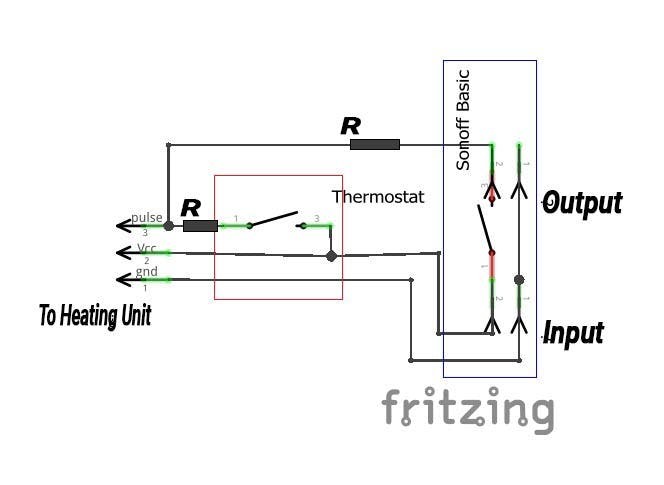
The connection was made in the following way:
Sonoff Tasmota - Honeywell thermostat
- INPUT Live - 4th terminal Live
- INPUT GND - 1st terminal GND
- OUTPUT Signal - 2nd terminal Signal
I mentioned before that for now, I’m not going to stress about the looks of this. The wife has been convinced and I can focus on the functionality and clearing any bugs that will happen. The good thing is that the original thermostat is still working. If I turn it up, it will override the Sonoff Tasmota based one. This should be a great backup for any unexpected events.
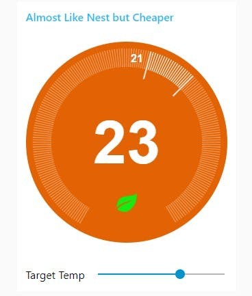
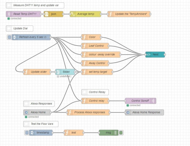
NodeRED Nest-alike interface
Please note that video may contain older NodeRed references, I’m constantly working on improving the design. These are small changes and the article files are kept up to date.
I came across this design online. It looks great, however upon close inspection, the widget isn’t really suited for NodeRED. It needs 5 payloads to be set, which is just not how node alike design works. It took me some time to figure out the best way of passing all that information over to update the widget and keep it functional.
I’m sure with time I’ll spend more time on the design so I could push all the needed updates with a single msg object. For now, it is what it is.
Temperature stream
DHT11 reports every X seconds back to the NodeRED server. I increased this frequency through the Tasmota’s console. Just run the command to set the frequency in sec:
TelePeriod <secs> Set telemetry period between 10 and 3600 seconds
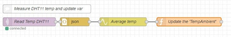
This is done mostly for tests, as I don’t want to wait for minutes to see if my bug fixes worked. Keeping frequency high will cause the heating to fire more frequently for shorter periods of time, so refrain from setting it to 10 sec for other than testing purposes.
The MQTT node pulls the data from:
sonoff/tele/SENSOR
and keeps the most useful data in the following objects:
msg.payload.DHT11.Temperature
msg.payload.DHT11.Humidity
To limit the errors, I added the smooth node to average the results and updated the flow variable:
NodeRED: Function Node - Update the 'TempAmbient'
flow.set('TempAmbient', msg.payload.DHT11.Temperature);
return msg;
Widget update
I decided that 5 seconds is a good refresh rate, therefore I’m pushing all needed values with this frequency. The only exception is the slider, which for obvious reason responds instantly.
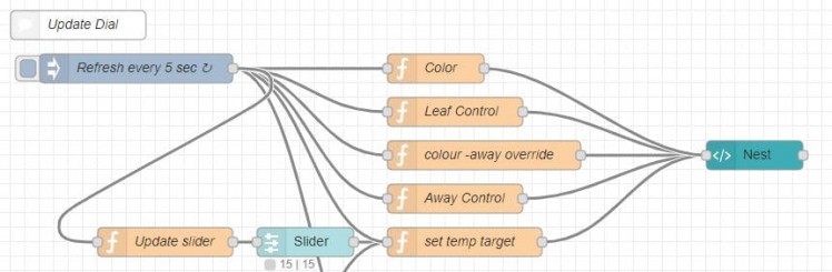
Each corresponding node sends the payload with the assigned topic to the nest-alike widget.
- colour (heating|cooling*|off & hvac_state)
- leaf (true|false & has_leaf)
- away (true|false & away)
- Ambient temp (number & ambient_temperature)
- Target temp (number & target_temperature)
*not in use
As you see, I opted out for the flow variables, so I could recall the value at any given time. I have a debug flow which basically reads all stored values.
- ‘TempAmbinet‘ – stores the current temp
- ‘TempTarget‘ – holds the temp target value
- ‘leaf‘ – displays leaf if needed
- ‘away‘ – displays away status if needed
- ‘heatingState‘ – changes colour of the display
- ‘heatingSwitch‘ – controls the state of the relay
The challenge was to actually make sure that the information is updated on “update” and when requested via other means (Alexa, etc). This is why you will see different conditions in the JavaScript. Each time the values are updated, sent to the flow variable and the widget is refreshed.
Slider
Testing revealed that an additional slider update (slider pushes the target temperature) is needed. Slider sends the payload (number) with the associated topic “slider) when it’s moved. On top of this, I want the slider to get into the correct position if multiple web interfaces are in place. To do this, every 5 sec I simply update the slider position to a current target temperature.
NodeRED: Function Node - Update slider'
msg.payload = flow.get('TempTarget');
return msg;
Relay control
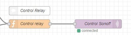
The relay controller is simple, it takes (for now) two inputs. Alexa’s true|false and the interaction that follows an update to the “heating Switch” flow variable. There is no need for an instant action, so for the simplicity, it runs on the same 5sec update frequency as the rest of the flow.
The relay is connected via MQTT. Node is posting ON|OFF commands to the topic:
sonoff/cmnd/POWER1
The function node accepts the true|false from Alexa and also changes the state of the input according to the ‘heatingSwitch’ flow variable.
NodeRED: Function Node - Control Relay'
if (msg.command === "TurnOffRequest"){
    msg.payload = "OFF";
    return msg;
}
if (msg.command === "TurnOnRequest"){
    msg.payload = "ON";
    flow.set('TempTarget', 21);
    return msg;
}
if (msg.topic === "update"){
    msg.payload = flow.get('heatingSwitch');
}
return msg;
Alexa integration
This is the first device I had to turn the “auto acknowledge” off. Instead of automatically assuming a response I have generated one as I want the ability to query the set temperature. In principle, msg.payload = true|false indicates if the request has been successful, and the templates found here do the rest. If you are new to Alexa and NodeRed, be sure to read this.
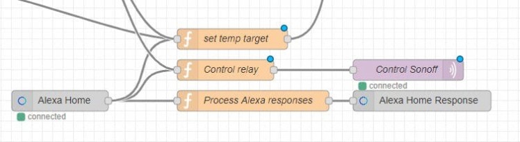
I decided to pass the acknowledgements separate (I know this is not the best way) to be able to control it all a little bit better. Properly each response should be given at the end of the command chain. Mine is risking not returning errors should these happen. Note, that to be consistent, I only update the variables, while the refresh loop, pushes the new values over to the widget.
NodeRED: Function Node - Process Alexa Responses'
// What is the thermostat's target temperature
if (msg.command === "GetTemperatureReadingRequest"){
    x =flow.get('TempTarget');
    msg.extra = {
    "temperatureReading": {
        "value": x},
    "applianceResponseTimestamp": new Date().toISOString()};
    msg.payload = true;
    return msg;
}
// Set the temperature to  (not lower than 10 or more than 30)
if (msg.command === "SetTargetTemperatureRequest"){
if (msg.payload < 10 || msg.payload > 30) {
    var range = {
        min: 10.0,
        max: 30.0
    }
    msg.payload = false;
    msg.extra = range;
}
else {
    msg.extra = {
        targetTemperature: {
            value: msg.payload
        }
    };
    msg.payload = true;
}
return msg;
}
// Turn it on
if (msg.command === "TurnOnRequest"){
    msg.payload = true;
    flow.set('away', false);
    flow.set('TempTarget', 21);
    return msg;

}
// Turn it off
if (msg.command === "TurnOffRequest"){
    msg.payload = true;
    flow.set('away', true);

    return msg;
Conclusion
It’s obvious, that the Google Home is missing, the controller also has no way of setting schedules yet, but I will add the Google Calendar integration for this. The tutorial and the video is long enough as it is, so this is something I will add in the next part. I’d like to introduce multiple temperature sensors so I could get a better feedback from how the heating system is performing.
If you want to get the latest updates to this project you can follow me via your preferred social media:
And if you feeling like buying me a coffee or supporting me in a more continuous way:
I hope you have enjoyed the project!
Schematics, diagrams and documents
Code
Credits
NotEnoughTech
Some say I run a decent tech blog online. The truth is I needed to find a hobby that fits between my bicycle rides. Robotics engineer in making at Labman.

Leave your feedback...