
Multifunctional rc transmitter using arduino

Made by mr-x
About the project
Lets build a NRF transmitter using arduino
Items used in this project
Hardware components

Software apps and online services
Story
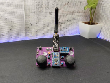
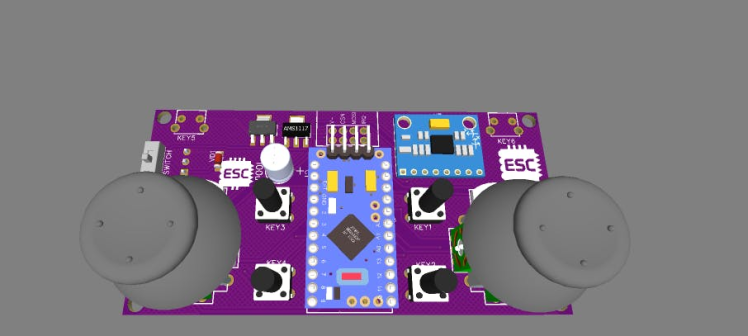
In this tutorial, I am showing how to build a MULTIFUNCTIONAL RC TRANSMITTER USING ARDUINO. This nrf transmitter consists of 2 joysticks 6 buttons switches and a gyroscope. so we can use this transmitter to control different RC projects. now let's get started
Step 1: COMPONENTS NEEDED1 / 3
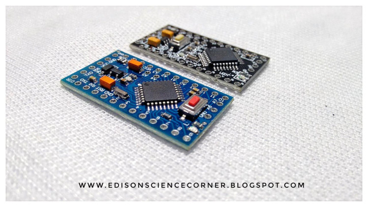
Arduino Pro MiniThe Arduino Pro Mini is a microcontroller board based on the ATmega328.It has 14 digital input/output pins (of which 6 can be used as PWM outputs), 6 analogue inputs, an onboard resonator, a reset button, and holes for mounting pin headers. A six pin header can be connected to an FTDI cable or Sparkfun breakout board to provide USB power and communication to the board. The Arduino Pro Mini is intended for semi-permanent installation in objects or exhibitions. The board comes without pre-mounted headers, allowing the use of various types of connectors or direct soldering of wires. The pin layout is compatible with the Arduino Mini. There are two versions of the Pro Mini. One runs at 3.3V and 8 MHz, the other at 5V and 16 MHz.The Arduino Pro Mini was designed and is manufactured by SparkFun Electronics.
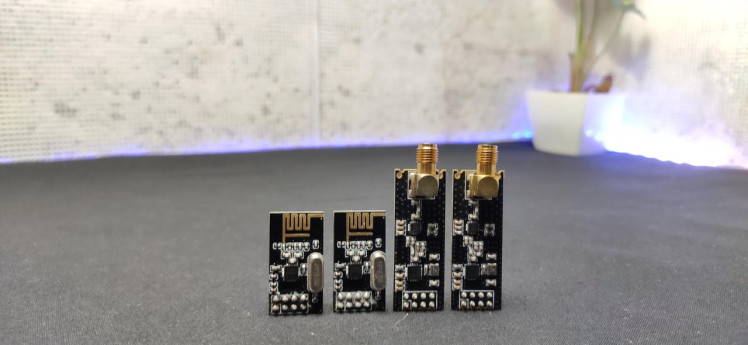
NRF24L01 Transceiver Module
nRF24L01 is a single-chip radio transceiver for the worldwide 2.4 - 2.5 GHz ISM
band. The transceiver consists of a fully integrated frequency synthesizer, a power amplifier, a crystal oscillator, a demodulator, modulator and an Enhanced ShockBurst™ protocol engine. Output power, frequency channels, and protocol setup are easily programmable through an SPI interface. Current consumption is very low, only 9.0mA at an output power of -6dBm and 12.3mA in RX mode. Built-in Power Down and Standby modes make power-saving easily realizable.
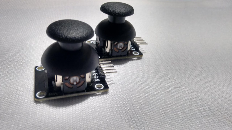
Joystick*2 (joystick breakout)
The Joystick module is similar to analogue joysticks found in gamepads. It is made by mounting two potentiometers at a 90 degrees angle. The potentiometers are connected to a short stick centred by springs. This module produces an output of around 2.5V from X and Y when it is at rest. position
mpu6050MPU6050 is a Micro Electro-mechanical system (MEMS), it consists of a three-axis accelerometer and three-axis gyroscope. It helps us to measure velocity, orientation, acceleration, displacement and other motion
AMS1117 3.3v voltage regulator
AMS1117-3.3V, 1A, SOT-223 Voltage Regulator IC is a series of low dropout three-terminal regulators with a dropout of 3.3V at 1A load current.
AMS1117 5.0 v voltage regulator
AMS1117-5.0V, 1A, SOT-223 Voltage Regulator IC is a series of low dropout three-terminal regulators with a dropout of 5V at 1A load current.
push button switches*6
100uf capacitor
Step 2: CIRCUIT DIAGRAM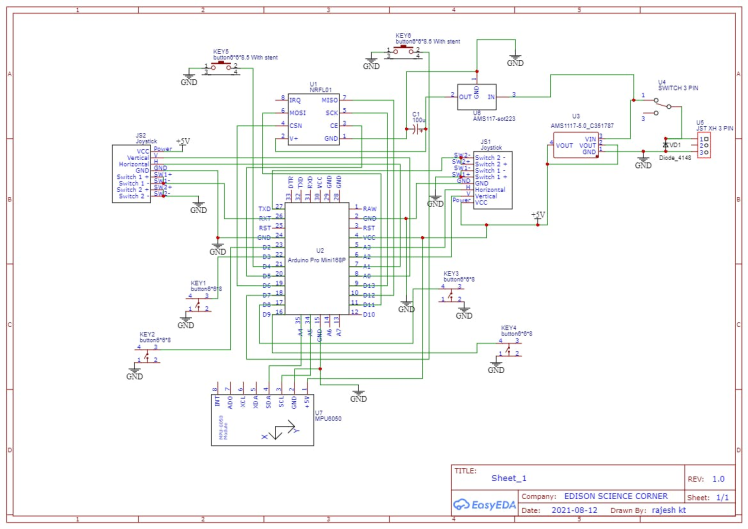
I modified a basic nrf transmitter circuit. I designed this circuit using easyeda. the Arduino pro mini is the brain of this transmitter. here I added switches and joystick for controlling.
Step 3: PCB DESIGNING and PCB MANUFACTURING1 / 4
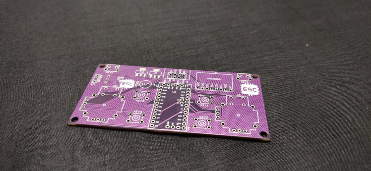
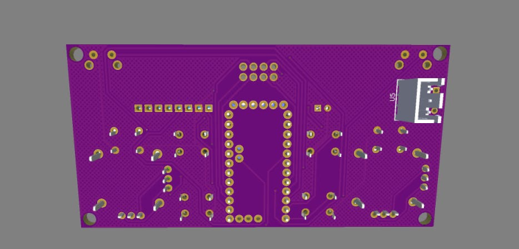

since this circuit has more components and connections I decided to design a PCB. so with the help of easyeda I converted the schematic to a PCB. after designing the PCB I downloaded the Gerber file and uploaded that into JLCPCB. I chose JLCPCB because they offer 5 high-quality PCBs for just 2$. I have received PCBs after 2 weeks. the purple colour PCBs are just awesome and high quality.
Step 4: SOLDERING1 / 4

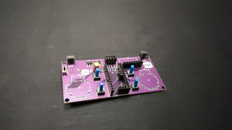
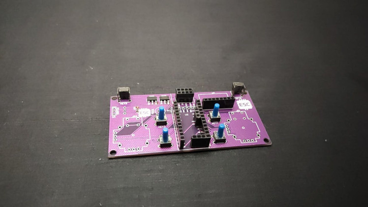
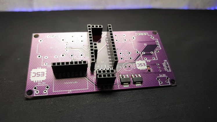
I grabbed all components and started the soldering job. I started from SMD components. then I placed female header pins for nerf module, mpu6050, and Arduino pro mini. then I added other components and it took 2 hours to finish the soldering job. Nothing more important here just place the component and solder that's it. remember to desolder the joystick from its module and re-solder to our custom PCB.
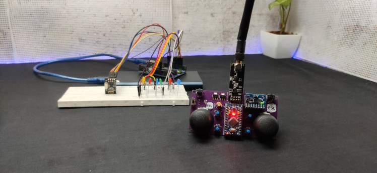
After finishing soldering I attached the joystick nob to the joystick then Arduino pro mini, mpu6050 and finally the nrf module. Then I connected the 7.4volt battery to the transmitter.
Step 5: Programming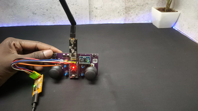
for programming, I connected a ch340 programmer to Arduino pro mini for uploading the code.
in the Arduino code First, I included the nrf library (go to sketch - include library - manage library and search for nrf24)then I defined the ce csn pins also the address this address should same as the receiver address. In the setup section, I started the communication. and radio. stop listening means this module act as the transmitter.
In the loop section first, I read the button state and then I send that data to the receiver using the radio. write command. This is how the transmitter works. then I uploaded this code to the transmitter. you can download the code from below
Step 6: Making Video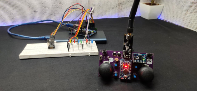
watch this video if you have any doubt
Schematics, diagrams and documents
Code
Credits
Related products


Leave your feedback...