
Motorized Camera Slider

Made by Gyro / 3D Printing / Photos & Video
About the project
Customizable camera slider with OLED screen and extended options
Project info
Difficulty: Difficult
Platforms: Arduino
Estimated time: 2 weeks
License: GNU General Public License, version 3 or later (GPL3+)
Items used in this project
Story
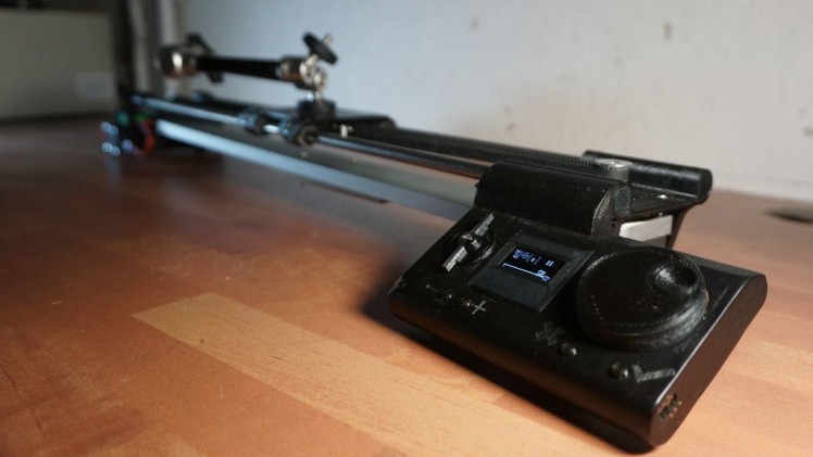
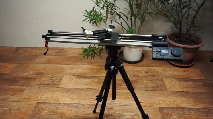
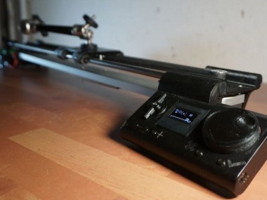
When it comes to video gear, camera sliders aren't considered a necessity but that doesn't stop me from making one. I knew from the beginning that using parts for 3D printers will make it cheap, accessible and adjustable. The fact that it's motorized makes it especially great for timelapses because it can move at a set speed for long periods of time. It also makes for very consistent motion at normal speeds. On top of that, the software also allows controlling it by just turning the knob like a mechanical slider. I'm extremely happy with the result. The only thing that's missing is a fluid camera head for smooth sliding and panning action. But I'll get one.
The slider I built is about half a meter long. The nice thing about the design it that it can be scaled up very easily. Just get longer rods. If you want you can use the electronics on a completely different slider or even modify a non-motorized one. The electronics will work with almost any stepper motor.
I'd also suggest watching the video as it contains some additional information
Step 1: Tools, Materials, Files
Tools:
- 3D printer
- Drill
- Soldering iron
- Screwdriver
- Metal hand saw
- x-acto knife
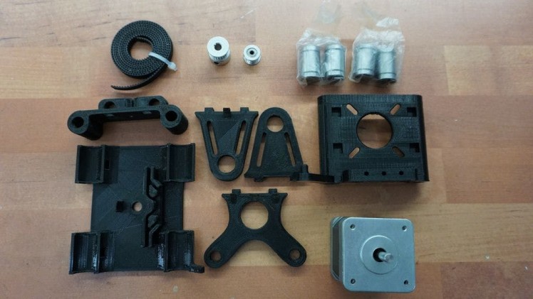
Materials for the mechanical part:
- NEMA 17 stepper motor
- GT2 pulley - I used one with 20 teeth but it really doesn't matter
- GT2 idler - 3mm bore
- GT2 timing belt - 2 meters for half a meter slider(better to have extra)
- 8mm smooth rod - I got a meter long one which I cut in half
- 4x LM8UU linear bearings
- M3 screws and nuts
- aluminum profile or M8 threaded rods for structural integrity
- 3D printed files
Materials for the electronics:
- Arduino pro micro
- A4988 stepper driver
- 0.96" OLED I2C screen
- Li-po battery 3S1P or a power bank(2.1A recommended)
- LE33CD-TR | 3.3V voltage regulator - substitutes: LM2931AD33R | L4931ABD33-TR - any other 3.3V regulator with the same pinout should work if it can handle at least 100mA
- 4x tactile buttons
- My rotary encoder - One file modified
- 9x 10k 0805 resistor
- 2x 1k 0805 resistor
- 2x 10k 1/4w resistor
- 3x 100nF 0805 capacitor
- 1x 2.2uF 0805 capacitor
- 2+2x MSW-1 micro switch - get the ones with wheels | 2 for the encoder + 2 for the slider
- step-up or step-down converter - depending on what battery you use
- 1x 3 pin right angle pin header
- 1x male and female 3pin 2.54mm Molex connector
Step 2: Assembling the Frame
 1 / 13
Skip to 4:33 in the video to get to the assembly of the frame.
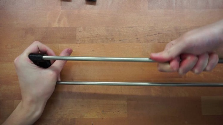
I started by cutting my meter long smooth rod in half with a hand saw. When I tried to insert it into to the printed parts if was way too tight so I had to use a drill with 8mm drill bit to enlarge it. That made it fit a lot better. Before I pushed the rods in tough I put the linear bearings on them as there isn't going to be an opportunity for that later. I didn't use any glue as the rods were held really snug but feel free to use some.
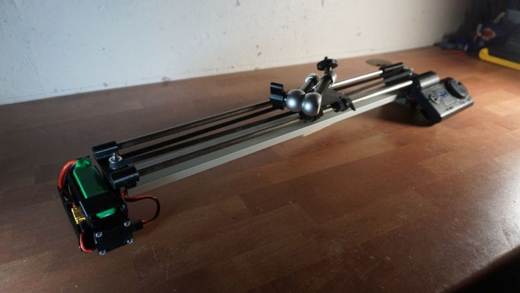
Next, I mounted the camera carriage with some zip ties. The whole thing started to look like a slider and the camera carriage actually moved smoothly which was a good sign so I put the stepper motor in place and secured it with four M3 screws. Following that, I mixed some five-minute epoxy to glue the legs. The two legs next to the motor may look Identical however one of them has a little notch while the other doesn't. The one without the notch goes on the side where electronics is going to be and the other one on the other side of course. I also found that once you have all three of them in place, It's good to put the slider on a flat surface and let the glue cure like that.
Next, I installed the pulley on the motor shaft and tightened the grub screws. On the other side of the slider, I installed the idler with an M3 screw and a locknut. I didn't tighten these all the way as I don't want to seize the bearing. It was time for the timing belt and here is where I want to remind you to get one that's long enough. No particular reason, just saying. I locked one end of the belt on the camera carriage by simply looping it around this ingenious hook, which is a design I stole from Thingiverse by the way. I then wrapped the belt around the pulley and idler and locked the other end on the camera carriage too. Making sure the belt was as tight as possible.
At this point, the slider is pretty much finished except for one crucial detail. It's supported entirely by the smooth rods. I simply took a right angle aluminum profile and screwed it to the bottom of the slider. There is a couple of holes designed where M3 screws will just self tap into the plastic. If you don't like that solution you can also use M8 threaded rods or you can come up with your own way. I've also put a small block of wood in the middle of the profile so I can attach it to a tripod but you don't have to do that.
Step 3: Assembling the Electronics
 1 / 4
1 / 4
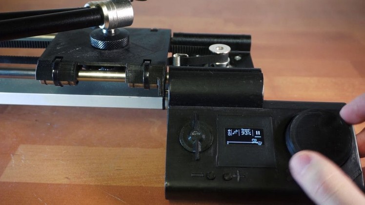
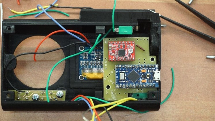
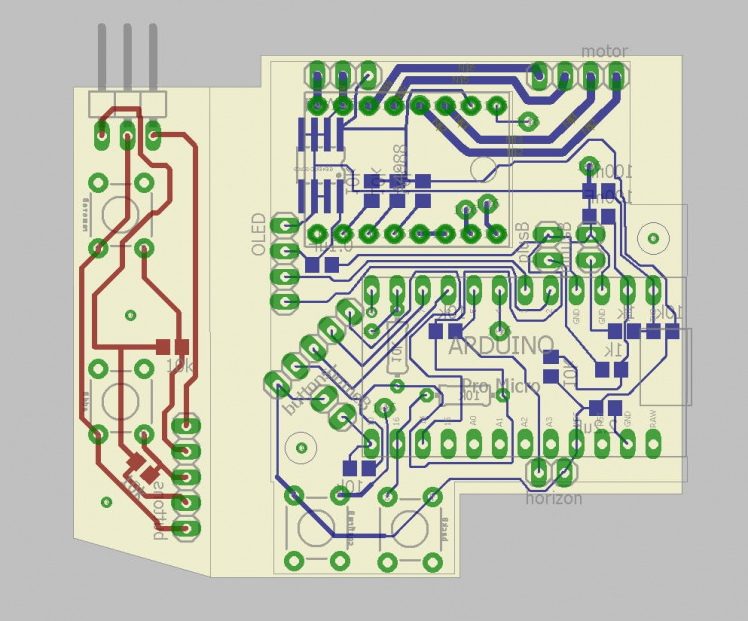
If a picture is worth thousands of words then the animation above is worth at least an entire paragraph. Yet it doesn't tell the whole story. First of all the PCBs. They are both single sided so they can be homemade easily. I have included the eagle files so you can modify it or get it made professionally. One thing to keep in mind is that a ton of stuff is actually connected to the main PCB and you'll need to run wires all over the place. Start with the OLED, move to the small PCB then wire the microswitches and encoder and finish with the motor and power wires.
Speaking of the encoder. This is therotary encoderI'm using but the base of the part is modified. The modified part is in the RAR file with 3d models but I've included it here too for convenience or confusion. Whichever it'll end up being.
Step 4: Power Supply
 1 / 8
1 / 8
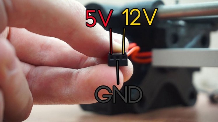
To power the slider, all you need is 5V for the electronics and 12V for the motor. I ran a cable along the aluminum profile towards the back end. I ended this cable with a Molex connector as shown above. I built two different power supplies.
Let's start with the Li-Po battery. The battery is linked in the materials above if you're interested. Since it a 3 cell battery it already outputs around 12V so I connected that directly. For the 5V I'm using a small adjustable step-down converter called Mini-360. There is just enough room for it in the model. The connector, converter, and wires are all held in place with a generous amount of hot glue.
For the power bank, it's a little bit different story. First of all, this is an old discontinued Xiaomi 10000mAh power bank so I'm sorry if your's doesn't fit but I've included the step file so anyone can modify it. The power bank must be able to provide at least 2.1A because the motor can get hungry. Since USB power banks provide 5V It's the 12V we need to worry about. Unfortunately, it's the 12V where most of the current will be drawn so a beefy step-up converter is necessary. I went with XL6009 which also adjustable so don't forget to set the trimmer first. Just like before, everything here is hot glued in place.
When it comes to the motor it will happily run even on 24V and you might even be able to make it run on 2 cell Lithium battery which is just 7.4V. If you find that your motor is getting really warm really quickly or it's simply unable to carry the camera you need to adjust the current limit. It's set with the potentiometer on the a4988 driver board as shown on the picture above. Honestly, I played with it for a while until the motor would get slightly warm after a couple minutes of use. There is a proper way of doing it but this is good enough :D
Step 5: Code
 1 / 3
1 / 3
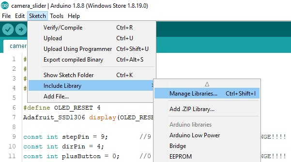
The video(@10:40) explains exactly which variable can be changed and what they do so I'm not going to repeat myself rather I'm will add even more information. I'm running Arduino 1.8.8 but it should work on almost any version. You will need to install a couple of libraries if you don't have them already. Go to sketch > Include Library > Manage Libraries... In the library manager look for Adafruit ssd1306 and Adafruit GFX and download them.
In the video, I said you'll have to figure out the number of steps on your own but I was in a good mood today and I made a simple program to calculate the number of steps. It's the one named steps_counter. All you have to do is to put the head on one end hit confirm button, wait till the slider gets to the other end and hit the button again. The number of steps will be sent over the serial port.
I've also mentioned the experimental version which I decided to put on my GitHub so if you want to contribute or just download it, that's where it'll be.
Conclusion
I've already used the slider couple of times and I have to say it's awesome. The shots are brilliant. Just like any other project, after finishing it I can think of hundred ways I could improve it. And most likely I will. For now, though I'll give it some time so I get comfy with it and then I'll find out what upgrades are really important.
Let me know if you need any help with this project or if I forgot anything. Also, consider subscribing to my youtube channel where I'll also post any big updates to the project.
Schematics, diagrams and documents
CAD, enclosures and custom parts
Code
Credits
Related products


Leave your feedback...