
Monitor Your Energy Bill Via Modbus, Mkr Wifi 1010 And Rs485
Made by Arduino / Home Automation
About the project
Connect a Modbus energy meter to an Arduino and monitor power consumption via Home Assistant.
Project info
Difficulty: Moderate
Platforms: Arduino
Estimated time: 5 hours
License: Creative Commons Attribution CC BY version 4.0 or later (CC BY 4+)
Story
ABOUT THIS PROJECT
If you really want to make your home smarter, you'll probably want start from your monthly bills (i.e. energy, gas, etc...). As some say, Good for Planet, The Wallet and The Bottom Line. Open source hardware is our way to reach sustainability in the home environment! This idea brought us to build a simple and secure solution, easy to integrate with any home automation software since it exposes data over MQTT (in our case we will show you how to integrate it into Home Assistant).
Overview
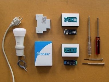
In order to measure the electrical energy consumption, we chose to use the Finder Energy Meter, since it is designed for DIN rail use and fits perfectly in the main cabinet of our house. The cool thing about this product is that it has an RS485 Modbus interface, an industrial standard communication protocol which makes talking to an Arduino really easy. In fact, Arduino has released an official shield, the MKR485 and two libraries to decode the protocol. As the main board, we chose the Arduino MKR WiFi 1010, since it shares the MKR form factor and has WiFi connectivity.
Setup
Warning! Check your country regulations about dealing with your house electrical system and be extremely careful because it can be deadly! If you don't know how, call an electrician. The first step is to install the meter in your electrical cabinet. To ensure you are working in a safe environment, turn off the power from the electrical terminal ahead of your system and double check with the multimeter that there is no voltage between the terminals.
Then place the energy meter inside your cabinet and connect live and neutral wires from the main breaker to the input of the meter, remember to use the color convention (blue for neutral and brown/black/grey for live in EU). The output has to be connected to the rest of the system.
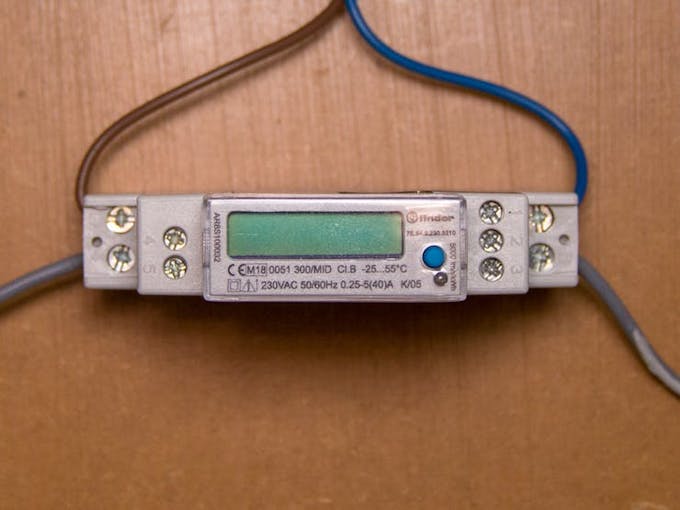
Main voltage connections. Wires above are input, wires beyond are outputs.
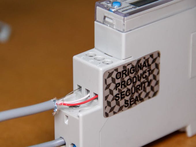
Done? It is time to screw in the RS485 connection! We will use twisted single pair cable with ground, typically used for phone lines. With this cable you can transmit over long distance (1.2 km). However we just use a cable long enough to exit the cabinet and place the arduino in an accessible place.
Finder RS485 connection
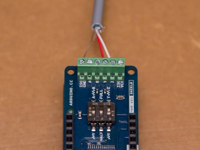
The RS485interface names its terminals A, B and COM.
A common de-facto standard is the use of: TX+/RX+ or D+ as
alternative for B (high for MARK i.e. idle), TX-/RX- or D- as
alternative for A (low for MARK i.e. idle)
Since the MKR shield supports also Full Duplex, you'll see two other terminals, Y and Z. Here we are going to screw the other end of the cable, since we know from the datasheet that half duplex communication happens only on Y and Z terminals. The COM terminal has to be connected to ISOGND. Since we use an half duplex connection and since the cabling is peer-to-peer, we have to setup the switches on the MKR485 shield to match our setup: we set HALF (2 to OFF) and termination on Y-Z (3 to ON); the first one does not matter. The termination is a resistance connecting the two data terminals, for dampening interferences.
This is it. Now you can close the cabinet and focus on the software side!
Software
Start your computer and open your IDE. You can use the Arduino IDE or Arduino Create Editor. The code is meeting the following requests:
- Modbus communication,
- WiFi management
- MQTT protocol
Modbus is and open source protocol for industrial sensors and machines. To make Arduino talk Modbus, we are going to use the Arduino Modbus library. This library packs all the handlers and makes hooking up any Modbus device really fast. Since we are going to read registers, following the datasheet of the meter, we can find all the information we need like function codes, address of the register and size of the register in words. But to make it clearer, let us explain how Modbus works:
Modbus messages follow a simple structure:
01 03 04 00 16 00 02 25 C7
0x01 is the Device Address
0x03 is the Function Code that tells the device if we want to read or write data *in this case read holding registers
0x04 for Byte Count00 16 - We send 4 bytes of register address (00 16) that tells the device what we want to read
00 02 - then the size of the register (00 02) in words (every word is 2 bytes long)
Last 4 bytes are CRC code. This code is generated from a math function over previous bytes, this ensures the message has been received correctly.
In Arduino all this stuff is handled in the if condition:
- // Created by Alberto Perro - Officine Innesto
- //
- // Read integer from a modbus device holding registers
- float readCurrent(){
- float ampere = 0.;
- //next command format the request and send it over RS485
- if (!ModbusRTUClient.requestFrom(0x01, HOLDING_REGISTERS, 0x0016, 2))
- {
- //Error Handling
- Serial.print("failed to read voltage! ");
- Serial.println(ModbusRTUClient.lastError());
- } else {
- uint16_t word1 = ModbusRTUClient.read(); //reading MSW from buffer
- uint16_t word2 = ModbusRTUClient.read(); //reading LSW from buffer
- int32_t milliamp = word1 << 16 | word2; //join words to retreive int
- ampere = milliamp/1000.0; //convert to ampere
- }
- return ampere;}
In the else part we have the response handler.
Since this register is two words long, we have to join them with binary math. We read the words from the buffer and store them in an unsigned integer 16-bit long (2 bytes or a word), then we join them in a signed integer 32-bit long bitshifting the first word to the left and apply an OR over the second word. This way we retreive the current measurement in mA, dividing it by 1000 we have current in ampere.
This same process is adapted to everything we want to read.
The rest of the code is dedicated to handling MQTT and WiFi networking.
Home Assistant Integration
Adding the meter to Home Assistant is pretty straightforward. Assuming you have a MQTT broker configured (Here is the guide), all you need to do is to add new definitions under the configuration.yaml file.
- sensor:
- - platform: mqtt
- name: "Main Voltage"
- state_topic: "energy/main/voltage"
- unit_of_measurement: "V"
Here you have to put the name of the measurement, the MQTT topic to read and the measurement unit of the quantity. Save the file, check the configuration and reload Home Assistant, now the measurements will appear on the main page.
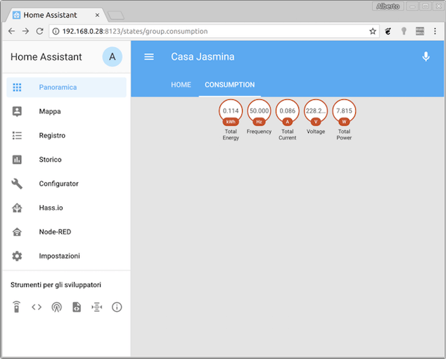
Home Assistant consumption panel showing current readings
Home Assistant will take care of creating graphs and automate processes triggered by your readings. This tutorial has finished, now it's up to you to add features and customize it for your own purposes!
CODE
Modbus RTU to MQTT bridge for Finder
This sketch provides a full bridge between the finder energy meter and mqtt. Developed to monitor electricity costs and usage in Casa Jasmina.
Modbus_RTU_to_MQTT_bridge_for_Finder by officine-innesto
Code
Credits
Related products


Leave your feedback...