
Build A Demo Matrix Keypad Lock With An Arduino

Made by marshall-gates / Displays / Security
About the project
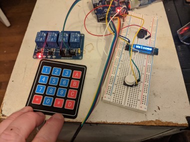
A demo project to read a 4x4 Keypad and drive a relay that controls a lock when the correct code is entered. It also has an OLED display to give the users prompt, a buzzer to provide audible feedback, and an override button to force the lock to open.
Project info
Difficulty: Easy
Platforms: Arduino
Estimated time: 1 hour
License: GNU General Public License, version 3 or later (GPL3+)
Items used in this project
Hardware components


View all
Story
Introduction
This project is designed to help you get familiar with several aspects of Arduino development. You will be accessing several inputs and creating data to be sent to various outputs. You will use a few of the many libraries available in the Arduino ecosystem.
We will be modeling a real world use for the Arduino, managing a secure door lock with an entry pass code and an override switch. The system will include a keypad for data entry, a screen for prompts and feedback, a relay to control the door lock, a buzzer to provide audio feedback and a momentary push button to act as an override access switch.
All of this will be connected to our Arduino Uno. You can use almost any 5 volt Arduino for this project as long as it has 11 available digital pins. You can use a 3.3 volt Arduino, but you will need an external power supply for the relay module. Everything else will function with 3.3 volts.
Let's get started.
Add The Keypad
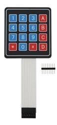
The keypad used in this demo is a 4 row by 4 column 16 key membrane keypad. It is one of the simplest implementations of a keypad.
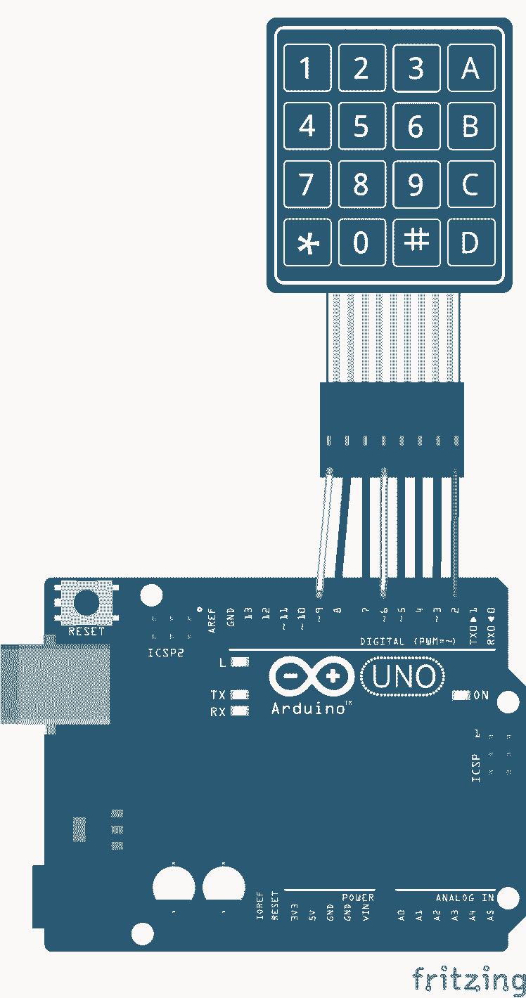
Wire The Keypad
The keypad is wired up as shown. Each pin in order from Row 1 through Col 4 into Digital inputs 9 through 2
Install the Library
The library we will be using is the Keypad Library by Mark Stanley and Alexander Brevig. It can be loaded in the Arduino IDE through the library manager. Go to Sketch > Include Library > Manage Libraries and search for "keypad". Click on the library, then click install.
Testing The Keypad
You can now run this small sample program that will validate that you have the keypad properly connected. It will print the decoded value for each keypad key press in the serial monitor.
- #include <Keypad.h>
- // Define Keypad setup
- const byte ROWS = 4;
- const byte COLS = 4;
- char hexaKeys[ROWS][COLS] = {
- {'1', '2', '3', 'A'},
- {'4', '5', '6', 'B'},
- {'7', '8', '9', 'C'},
- {'*', '0', '#', 'D'}};
- byte rowPins[ROWS] = {9, 8, 7, 6};
- byte colPins[COLS] = {5, 4, 3, 2};
- char customKey;
- Keypad customKeypad = Keypad(makeKeymap(hexaKeys), rowPins, colPins, ROWS, COLS);
- void setup()
- {
- Serial.begin(115200);
- Serial.println("Keypad Test");
- }
- void loop()
- {
- customKey = customKeypad.getKey();
- if (customKey)
- {
- Serial.print("Key = ");
- Serial.println(customKey);
- }
- }
Using a 4x3 Keypad
If you use a 4x3 keypad, then you can omit the last column, Col 4, which connects to input D2. In the code you will need to replace the keypad definition with this one:
- // This is for 4x3 keypad
- const byte ROWS = 4;
- const byte COLS = 3;
- char hexaKeys[ROWS][COLS] = {
- {'1', '2', '3'},
- {'4', '5', '6'},
- {'7', '8', '9'},
- {'*', '0', '#'}};
- byte rowPins[ROWS] = {9, 8, 7, 6};
- byte colPins[COLS] = {5, 4, 3};
Add the Breadboard
To support the rest of the prototyping we will use a solder-less breadboard. A good discussion of what a solder-less breadboard is and how it is used can be found here.
Wire the Breadboard
We will go ahead and connect the power rails. One for 5 Volts the other for 3.3 Volts, as show below. Note that I am using black wires for the ground connections, red for the +5 volts and orange for the +3.3 volts. I set the top rail to be 3.3 volts and the bottom one to be the 5 volt rail.
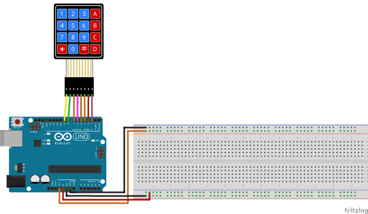
The top rail will be the 3.3 volt and ground connections and the bottom will be the 5 volt and ground connections. After you have done this, the test program should continue to run as before.
Add The OLED Display
The OLED display is used to prompt the user to enter the pass code and tell them if they got it right or wrong.. It is not a very large display so there is not a lot of room for many details. A good discussion of the 1306 based OLED displays can be found on the Adafruit site.
First connect the GND pin on the display to the ground rail. Then the Vcc pin to the 3.3 volt rail, This will power the display. Now we will connect the I2C connection SCL and SDA. As you can see in the diagram below, the SCL and SDA pins are in the upper left corner of the Arduino next to the USB Connector. On some Arduino devices they are A5 (SCL) and A4 (SDA). A nice discussion of I2C can be found here.
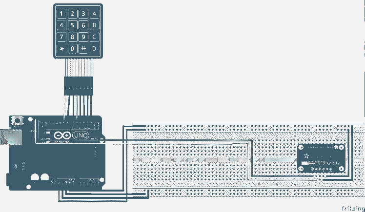
Adding The Libraries
The OLED display requires the built in Wire library to communicate over I2C and the Adafruit SSD1306 library to control the OLED display.. To add the SSD1306 library, go to Sketch > Include Library > Manage Libraries and search for "SSD1306". Click on the Adafruit SSD1306 library, then click install. Since this is an I2c connected device we need to be aware of its address. The display I am using is 0x3C. This is used in the display.begin() call that sets up the actual display.
Testing the display
For this, we will just display every key press on the screen instead of sending it through the serial interface. Replace the existing code with this code to test the display.
- #include <Wire.h>
- #include <Adafruit_SSD1306.h>
- #include <Keypad.h>
- #define SCREEN_WIDTH 128 // OLED display width, in pixels
- #define SCREEN_HEIGHT 32 // OLED display height, in pixels
- // Declaration for an SSD1306 display connected to I2C (SDA, SCL pins)
- #define OLED_RESET 4 // Reset pin # (or -1 if sharing Arduino reset pin)
- Adafruit_SSD1306 display(SCREEN_WIDTH, SCREEN_HEIGHT, &Wire, OLED_RESET);
- const byte ROWS = 4;
- const byte COLS = 4;
- char hexaKeys[ROWS][COLS] = {
- {'1', '2', '3', 'A'},
- {'4', '5', '6', 'B'},
- {'7', '8', '9', 'C'},
- {'*', '0', '#', 'D'}};
- byte rowPins[ROWS] = {9, 8, 7, 6};
- byte colPins[COLS] = {5, 4, 3, 2};
- char customKey;
- Keypad customKeypad = Keypad(makeKeymap(hexaKeys), rowPins, colPins, ROWS, COLS);
- void setup()
- {
- Serial.begin(115200);
- // SSD1306_SWITCHCAPVCC = generate display voltage from 3.3V internally
- // Address 0x3C for 128x32 or 0x3D for 128x64
- if (!display.begin(SSD1306_SWITCHCAPVCC, 0x3C))
- {
- Serial.println(F("SSD1306 allocation failed"));
- for (;;)
- ; // Don't proceed, loop forever
- }
- // Show initial display buffer contents on the screen --
- // the library initializes this with an Adafruit splash screen.
- display.display();
- delay(2000); // Pause for 2 seconds
- // Set up the display for big characters
- display.setTextSize(2); // Draw 2x-scale text
- display.setTextColor(SSD1306_WHITE);
- // Clear the display and show it.
- display.clearDisplay();
- display.display();
- }
- void loop()
- {
- customKey = customKeypad.getKey();
- if (customKey)
- {
- display.clearDisplay();
- display.setCursor(0, 0);
- display.print("Key = ");
- display.print(customKey);
- display.display();
- }
- }
Running this should cause the display to show the Adafruit logo for a couple of seconds then go blank. Pressing any key will display "Key = " and the decoded key pressed.
Adding The Security Logic
Now that we can display information to and get information from the user, it is time to add the basic security logic to the application.
Given that we have a master pass code that will open the door, we want to collect key presses until we have that many characters. Then if the collected key presses match the master pass code, we can report success and clear the collected data, otherwise we report the failure and clear the collected data.
We will start out defining how long the password should be in bytes
- #define Password_Length 8
Then we will set up a place to hold the key presses, along with the actual master password.
- char Data[Password_Length];
- char Master[Password_Length] = "123A456";
Now let us have a counter of the number of key presses.
- byte data_count = 0;
There is no additional code in the setup function, but everything else goes in the loop function. Starting at the top of the loop, we will go to the top of the screen and prompt the user for the password.
- display.setCursor(0, 0);
- display.setTextSize(1); // Draw normal-scale text
- display.setTextColor(SSD1306_WHITE);
- display.print(F("Enter Password:"));
- display.display();
Now in the block that is executed when there is a key pressed. We will add that key press to the array of characters that have been entered and increment the counter. Now we will display an asterisk instead of the character.
- Data[data_count] = customKey;
- display.setCursor(data_count * 8, 20);
- display.print('*');
- display.display();
- data_count++;
Now if we have enough characters, let's see if it is a match. If so Welcome the user otherwise tell them Access Denied. Either way, report the success or failure to the serial monitor, clear out all the key presses, and start over.
- if (data_count == Password_Length - 1)
- {
- display.clearDisplay();
- display.setCursor(0, 0);
- if (!strcmp(Data, Master))
- {
- // The passcode matches, so tell the user they can enter
- display.setTextSize(3); // Draw 3X-scale text
- display.print("Welcome");
- display.display();
- Serial.println("Open");
- delay(2000);
- }
- else
- {
- display.setTextSize(2); // Draw 2X-scale text
- display.setTextColor(SSD1306_BLACK, SSD1306_WHITE);
- display.print(" Access n Denied ");
- display.display();
- Serial.println("Failed");
- delay(2000);
- }
- clearData();
- display.clearDisplay();
- }
Here is the updated code with this logic added along with the new clearData() function.
- #include <Wire.h>
- #include <Adafruit_SSD1306.h>
- #include <Keypad.h>
- #define SCREEN_WIDTH 128 // OLED display width, in pixels
- #define SCREEN_HEIGHT 32 // OLED display height, in pixels
- // Declaration for an SSD1306 display connected to I2C (SDA, SCL pins)
- #define OLED_RESET 4 // Reset pin # (or -1 if sharing Arduino reset pin)
- Adafruit_SSD1306 display(SCREEN_WIDTH, SCREEN_HEIGHT, &Wire, OLED_RESET);
- #define Password_Length 8
- const byte ROWS = 4;
- const byte COLS = 4;
- char hexaKeys[ROWS][COLS] = {
- {'1', '2', '3', 'A'},
- {'4', '5', '6', 'B'},
- {'7', '8', '9', 'C'},
- {'*', '0', '#', 'D'}};
- byte rowPins[ROWS] = {9, 8, 7, 6};
- byte colPins[COLS] = {5, 4, 3, 2};
- char Data[Password_Length];
- char Master[Password_Length] = "123A456";
- byte data_count = 0;
- char customKey;
- Keypad customKeypad = Keypad(makeKeymap(hexaKeys), rowPins, colPins, ROWS, COLS);
- void setup()
- {
- Serial.begin(115200);
- // SSD1306_SWITCHCAPVCC = generate display voltage from 3.3V internally
- // Address 0x3C for 128x32 or 0x3D for 128x64
- if (!display.begin(SSD1306_SWITCHCAPVCC, 0x3C))
- {
- Serial.println(F("SSD1306 allocation failed"));
- for (;;)
- ; // Don't proceed, loop forever
- }
- // Show initial display buffer contents on the screen --
- // the library initializes this with an Adafruit splash screen.
- display.display();
- delay(2000); // Pause for 2 seconds
- // Clear the display and show it.
- display.clearDisplay();
- display.display();
- }
- void loop()
- {
- display.setCursor(0, 0);
- display.setTextSize(1); // Draw normal-scale text
- display.setTextColor(SSD1306_WHITE);
- display.print(F("Enter Password:"));
- display.display();
- customKey = customKeypad.getKey();
- if (customKey)
- {
- Data[data_count] = customKey;
- display.setCursor(data_count * 8, 20);
- display.print('*');
- display.display();
- data_count++;
- }
- if (data_count == Password_Length - 1)
- {
- display.clearDisplay();
- display.setCursor(0, 0);
- if (!strcmp(Data, Master))
- {
- // The passcode matches, so tell the user they can enter
- display.setTextSize(3); // Draw 3X-scale text
- display.print("Welcome");
- display.display();
- Serial.println("Open");
- delay(2000);
- }
- else
- {
- display.setTextSize(2); // Draw 2X-scale text
- display.setTextColor(SSD1306_BLACK, SSD1306_WHITE);
- display.print(" Access n Denied ");
- display.display();
- Serial.println("Failed");
- delay(2000);
- }
- clearData();
- display.clearDisplay();
- }
- }
- void clearData()
- {
- while (data_count != 0)
- {
- Data[data_count--] = 0;
- }
- return;
- }
Adding the Lock Relay
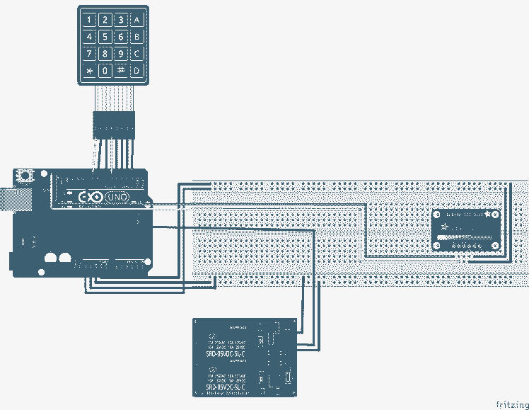
The relay module will allow us to manipulate the high voltage necessary to drive the lock release. We will use pin 10 to control the relay. The module requires 5 volts. In a real situation, you should use a separate power supply for the relay, but in this small implementation we can drive it from the 5 volt pin on the Arduino. Wire the Vcc pin to the 5 volt rail on the breadboard and the Gnd pin to the ground rail. Finally connect the Int 1 pin on the relay module to D10 on the Arduino.
Code changes to support the Relay
The relay module that I am using is active low. This means that writing LOW to the pin will activate the relay. You will see this in the code. So let us modify the test code to support the relay module.
After the declaration of the display object add this #define statement to identify the pin we will be using to control the relay.
- #define LOCK_RELAY_PIN 10
Next in the setup function, after we initialize the display we will set up the pin to control the relay module. Note that we immediately set the pin HIGH to keep the relay from activating.
- pinMode(LOCK_RELAY_PIN, OUTPUT);
- digitalWrite(LOCK_RELAY_PIN, HIGH);
Finally when the correct pass code is entered, we need to drive the pin LOW to open the door. In the loop function, after we print out that the door has been opened, we need to toggle the lock relay pin. We will leave it LOW for 5000 milliseconds, or 5 seconds, to give the user time to open the door before rearming the lock by setting the pin HIGH.
Replace the delay(2000); with this code.
- digitalWrite(LOCK_RELAY_PIN, LOW);
- delay(5000);
- digitalWrite(LOCK_RELAY_PIN, HIGH);
Recompile the application and upload it to the Arduino. You should now see the relay energize when a valid code is entered on the keypad at the prompt.
Add A Buzzer
The buzzer gives the user audible feedback as to the success or failure of entering the lock code. We will make it click on each key press, generate a pleasant sound on successful unlocking of the door and an irritating sound on failure.
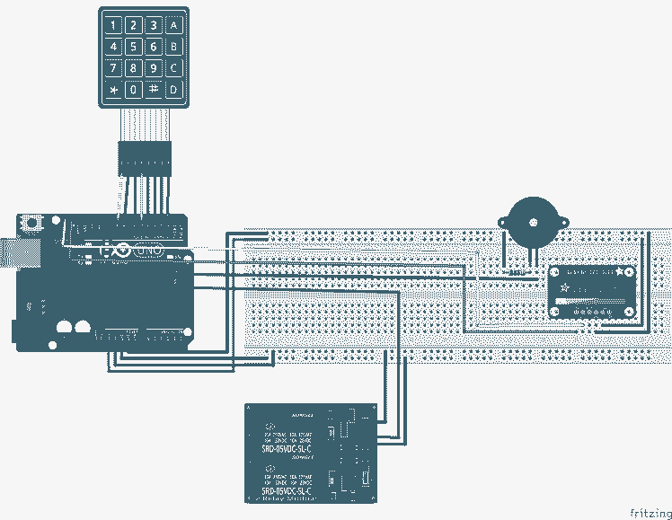
The buzzer is simple to wire. Add it to the breadboard. Tie one leg of the buzzer to one side of the optional 100 ohm resister, Connect the other side of the resistor to the ground rail. The other side of the buzzer will be connected to pin D11 on the Arduino.
Code to drive the Buzzer
The sound generation will be supplied by the built in Tone library functions: tone() and noTone(). The tone*( function takes a pin number and a frequency in Hertz. The noTone() function just needs a pin number. A good example of playing melodies with the tone functions can be found here. You will see that I use some of the constants from this example.
Let's add the code to define a few constants. These will go after the define of the lock relay pin.
- #define BUZZER_PIN 11
- #define NOTE_G4 392
- #define NOTE_D5 587
- #define NOTE_C6 1047
Now to add the key click sound for button presses. In the loop function replace the first if block with this code.
- if (customKey)
- {
- tone(BUZZER_PIN, 33);
- Data[data_count] = customKey;
- display.setCursor(data_count * 8, 20);
- display.print('*');
- display.display();
- data_count++;
- noTone(BUZZER_PIN);
- }
We are just playing a very low frequency sound for just as long as it takes to display the asterisk for each key press.
Next we will add the success tones. For this we are just going to replace the delay(5000); in the passcode matches block of code with this code
- // Play Ding for half a second
- tone(BUZZER_PIN, NOTE_D5);
- delay(500);
- // Play Dong for half a second
- tone(BUZZER_PIN, NOTE_G4);
- delay(500);
- // Turn off the buzxzer
- noTone(BUZZER_PIN);
- // Wait for the rest of the 5 seconds, only 4 now.
- delay(4000);
Finally the failure tones. In the access denied block, replace the delay(2000) with this code to also play the warning tone.
- // Start the annoying sound
- tone(BUZZER_PIN, NOTE_C6);
- delay(2000);
- // And stop it now.
- noTone(BUZZER_PIN);
Add an Override to Unlock
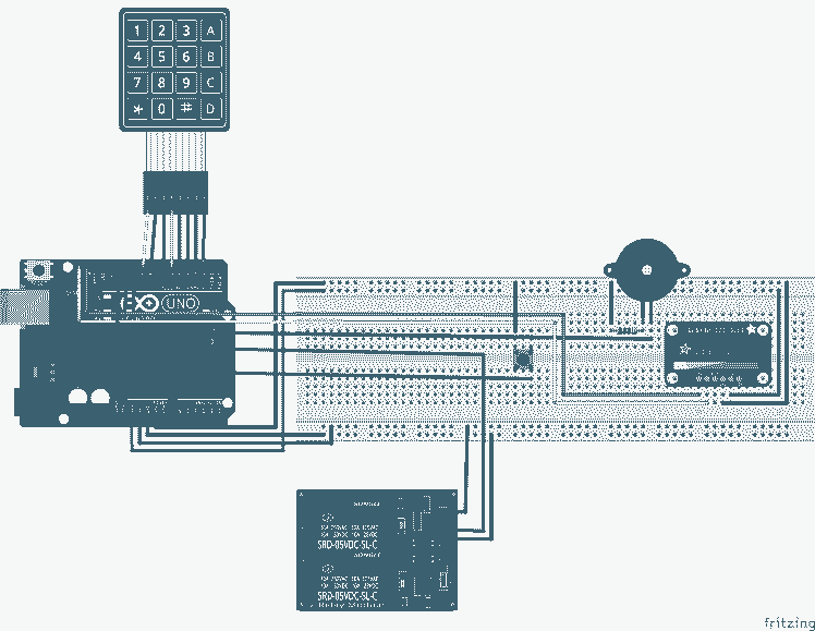
The last addition is an override button that would go inside the secured area to allow someone to open the door to leave. We will be using a momentary push button for this. Place the button in the center of the bread board so that the pins straddle the gap between the rows of pins. This will help us to properly isolate the connections of the switch.
Most momentary contact push buttons switches have 4 pins. Two of them tied together in pairs. Pressing the button will then connect the two sides of the switch. the switch in the diagram below is placed so the one pair is on top and the other below. If, after connecting everything and updating the code, the system acts like you are always pressing the override, take the switch out and turn in 90 degrees and re insert it and it should behave properly.
Code changes to Support the Override
For this, we need to reed the override pin every time through the loop if there is not a key press available from the keypad. If the button is pressed, then we notify the user and open the door, playing the chime as if the user entered a valid code.
First we add the constant that defines the pin that will read the override button. This goes right after the constant for the buzzer pin
- #define OVERRIDE 12
Next we add this code to the setup function to initialize the pin for reading. Note that we tell the Arduino to use its built in pull up resistor. This goes right after the defintions of the lock relay pin.
- // Setup the Override button input pin
- pinMode(OVERRIDE, INPUT_PULLUP);
Finally, we replace the loop function with these two functions.
- void loop()
- {
- display.setCursor(0, 0);
- display.setTextSize(1); // Draw normal-scale text
- display.setTextColor(SSD1306_WHITE);
- display.print(F("Enter Password:"));
- display.display();
- customKey = customKeypad.getKey();
- if (customKey)
- {
- tone(BUZZER_PIN, 33);
- Data[data_count] = customKey;
- display.setCursor(data_count * 8, 20);
- display.print('*');
- display.display();
- data_count++;
- noTone(BUZZER_PIN);
- }
- if (data_count == Password_Length - 1)
- {
- display.clearDisplay();
- display.setCursor(0, 0);
- if (!strcmp(Data, Master))
- {
- // The passcode matches, so tell the user they can enter
- display.setTextSize(3); // Draw 3X-scale text
- display.print("Welcome");
- display.display();
- Serial.println("Open");
- openLock();
- }
- else
- {
- display.setTextSize(2); // Draw 2X-scale text
- display.setTextColor(SSD1306_BLACK, SSD1306_WHITE);
- display.print(" Access n Denied ");
- display.display();
- Serial.println("Failed");
- // Start the annoying sound
- tone(BUZZER_PIN, NOTE_C6);
- delay(2000);
- // And stop it now.
- noTone(BUZZER_PIN);
- }
- clearData();
- display.clearDisplay();
- }
- else
- {
- if (digitalRead(OVERRIDE) == LOW) {
- display.clearDisplay();
- display.setCursor(0, 0);
- display.setTextSize(3); // Draw 3X-scale text
- display.print(" Enter");
- display.display();
- Serial.println("Override");
- openLock();
- clearData();
- display.clearDisplay();
- }
- }
- }
- void openLock()
- {
- // Energize the relay by driving the control pin LOW
- digitalWrite(LOCK_RELAY_PIN, LOW);
- // Play Ding for half a second
- tone(BUZZER_PIN, NOTE_D5);
- delay(500);
- // Play Dong for half a second
- tone(BUZZER_PIN, NOTE_G4);
- delay(500);
- // Turn off the buzxzer
- noTone(BUZZER_PIN);
- // Wait for the rest of the 5 seconds, only 4 now.
- delay(4000);
- // De-energize the relay
- digitalWrite(LOCK_RELAY_PIN, HIGH);
- }
This refactors the open the door code into another function and then calls it from both the override and the successful password entry section.
Wrapping it all up
Now that everything is together, you should be able to exercise all the functionality just like this short demonstration of my prototype going through a successful entry, a failed code entry, and an override entry.
Future Enhancements
There are many enhancements you might want to add.
- A time out on entry that will clear the existing key presses and allow you to start over.
- Make one of the keys be a backspace key to delete the previous key.
- Make one of the keys be a reset key that will clear the existing key presses and allow you to start over.
- Adding more than one pass code and tracking who's pass code was used.
Above all you should have fun experimenting with this project.
Schematics, diagrams and documents
Code
Credits
Related products


Leave your feedback...