
Raspberry Pi Magnetometer
Made by Digilent Inc / Sensors
About the project
In this project, we use an MCC 118 Voltage Measurement DAQ HAT and Raspberry Pi to read the linear output from a magnetic field sensor.
Project info
Difficulty: Moderate
Platforms: Digilent, Raspberry Pi
Estimated time: 3 hours
License: GNU General Public License, version 3 or later (GPL3+)
Items used in this project
Hardware components


Story
Software setup
To use the MCC DAQ 118 hat with the Raspberry Pi, the first thing to do is install the libraries provided by the manufacturer.
Here are the steps:
1.Open a terminal window if using the graphical interface and update your package list:
- sudo apt update
2. Optional: Update your installed packages and reboot:
- sudo apt full-upgrade
- sudo reboot
3. If not installed install git:
- sudo apt install git
4. Download the package offered by the manufacturer to your user folder with git:
- cd ~
- git clone https://github.com/mccdaq/daqhats.git
5. Install the library. The installer will ask if you want to install Python 2 and Python 3 support.
- cd ~/daqhats
- sudo ./install.sh
If you want to perform a firmware update or to read more information about the MCC 118 you can visit the MCC DAQ HAT Library documentation.
Hardware setup
For this project, we will need some components besides Raspberry Pi and MCC 118. To create the magnetic field sensor, we will need the following components: AD22151 (Magnetic Field Sensor), three resistors that we will size later, a 0.1µF capacitor, a breadboard, and some wires. To start this project, the first configuration offered by the manufacturer in the datasheet will be used (AD22151 Data Sheet).

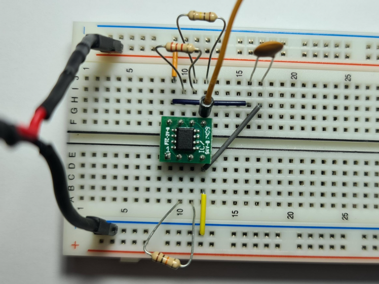
R1 is a resistor used for temperature compensation, 10K was chosen from the graph provided, to compensate for small values in temperature deviations.
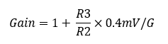
R2 and R3 are used to set the Gain in this circuit. The values were chosen after performing the calculation with the formula written below. The value of R3 is 100K and for R2, after performing the computer, the value of 2.2K was chosen. Thus, a gain of approximately 19 mV/G is obtained.
Now that we have the measuring circuit, we need to power it. In order to supply 5V and ground, the GPIO ports are used for this task, more precisely port 4 for 5V and port 6 for ground.

The last step for the hardware is to connect the sensor output to one of the MCC 118 channels, channel 0 for this project. The output is between 0 and 5V and the value of 2.5V represents the threshold between the positive and negative output values of the circuit. Further, in the project, the program flow part mentions how you can modify the code to be able to connect several sensors at once.
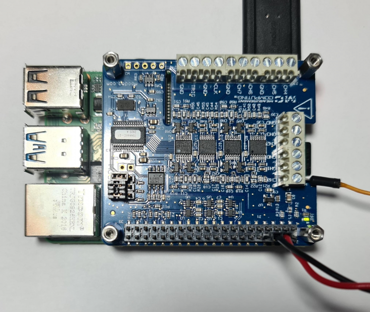
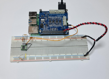
After completing these steps, your circuit should look similar to the one in the image below.

Program flow
After mounting the components and installation of libraries, the two files attached below must be saved in the same folder. "daqhats_utils.py" is taken from the examples folder, it is in the "daqhats" folder which is installed after performing the steps for installing the libraries using git. “scan.py" is the main file for this project.
Library imports
- from __future__ import print_function
- from sys import stdout
- from time import sleep #allows to introduce a delay in the execution of your program
- from daqhats import mcc118, OptionFlags, HatIDs, HatError #import labrary mcc118 to use all the methods for MCC118
- from daqhats_utils import select_hat_device, enum_mask_to_string,
- chan_list_to_mask
To perform the measurement we need some functions offered in the libraries in the git repository and daqhats_utils. We import the entire mcc118 class and some help functions. "OptionFlags" is used to set the mode for scanning the values provided by the channels on the raspberry hat and to identify the id and errors we use the "HatIDs" and "HatError" functions.
Constant declaration and print information
- gain_constant = 52.1376 #determined by the above formula
- v_ref = 2.3
- scan_rate = 2000.0
To determine the value of the magnetic field intensity we use the two constants, gain_constant, and v_ref. "gain_constant" is determined by the above formula, this constant needs to be changed to respect the voltage gain of the circuit. This constant is equal to the inverse of the calculated gain (1/gain). "v_ref" is the voltage reference for the zero point, all the values above it is positive numbers, all the values under it are negative numbers. These two are used in the print function at the end of the program.
- print('{:10.5f}'.format((read_result.data[index+i]-v_ref)*gain_constant), 'Gaus', end='')
- #print('{:10.5f}'.format(read_result.data[index+i]), 'V', end='') #Use to measured the threshold
The program will show in the terminal a number consisting of a maximum of ten digits and five digits after the comma. To calibrate the out, uncomment the next line and change the value of "v_ref" with the value measured.
The per-channel rate of the internal scan clock is set in the variable "scan_rate" and the expected maximum rate of an external scan clock, max 100 000.
Channels declaration
- channels = [0] #if you want to use other channel replace "0" with the channel you want
- #or to add more channels add to array like in this example channels = [0, 1, 2, 3, 4, 5, 6, 7]
- channel_mask = chan_list_to_mask(channels)
- num_channels = len(channels)
The channels used must be declared in a vector. To add more channels, modify the vector by adding the channels you want to use. For example:
- channels = [0, 1, 2, 3, 4, 5, 6, 7]
uses all the eight channels to measure. All the functions in MCC 118 class use vectors to determine the channels in use and for this, it is needed to know the length of the vector.
Read and display data
- total_samples_read = 0
- read_request_size = READ_ALL_AVAILABLE
- timeout = 5.0
- while True:
- read_result = hat.a_in_scan_read(read_request_size, timeout)
- # Check for an overrun error
- if read_result.hardware_overrun:
- print('nnHardware overrunn')
- break
- elif read_result.buffer_overrun:
- print('nnBuffer overrunn')
- break
- samples_read_per_channel = int(len(read_result.data) / num_channels)
- total_samples_read += samples_read_per_channel
- # Display the last sample for each channel,in a maximum number of 12 digits.
- print('r{:12}'.format(samples_read_per_channel),
- ' {:12} '.format(total_samples_read), end='')
- #r is use to write over the existing line
- if samples_read_per_channel > 0:
- index = samples_read_per_channel * num_channels - num_channels
- for i in range(num_channels):
- #Display the value number of 10 digits and 5 digits after the comma
- print('{:10.5f}'.format((read_result.data[index+i]-v_ref)*gain_constant), 'Gaus', end='')
- #print('{:10.5f}'.format(read_result.data[index+i]), 'V', end='') #Use to measured the threshold
- stdout.flush()
- sleep(0.1)
- print('n')
The readings are executed in a loop that continues until the user stops the scan or an overrun error is detected. All the available samples are read (up to the size of the read_buffer). Since the read_request_size is set to -1 (READ_ALL_AVAILABLE), the function “hat.a_in_scan_read” returns immediately with samples are available at the moment and the timeout parameter is ignored. The function “hat.a_in_scan_read” returns multiple elements: running, hardware overrun, buffer overrun, triggered, and timeout with all is a bool type and data that is a list o float. The data return is the one we will use next to display the information read from the buffer.
- samples_read_per_channel = int(len(read_result.data) / num_channels)
- total_samples_read += samples_read_per_channel
“samples_read_per_channel” is used to show the number in the data list at which the purchase was made and displayed. “total_samples_read” stores the total number of samples. These numbers are displayed in 12-digit format.
If there are samples in the buffer, then the program will start displaying. For each channel its result is saved to a certain value in the list, the position for each value is a multiple of the number of channels used. To display we use an index that saves for each reading the position of each sample on each channel.
- if samples_read_per_channel > 0:
- index = samples_read_per_channel * num_channels - num_channels
- for i in range(num_channels):
- #Display the value number of 10 digits and 5 digits after the comma
- print('{:10.5f}'.format((read_result.data[index+i]-v_ref)*gain_constant), 'Gaus', end='')
- #print('{:10.5f}'.format(read_result.data[index+i]), 'V', end='') #Use to measured the threshold
Launch the script
To launch the python script, open a terminal in the folder where you saved the 2 files with the command below.
- python scan.py
After that, in the terminal will appear the address at which MCC 118 is located, the way in which the hat works, the channels in use and the scan rate at which it works is set to work. After pressing the ENTER key, the program will start to scan.
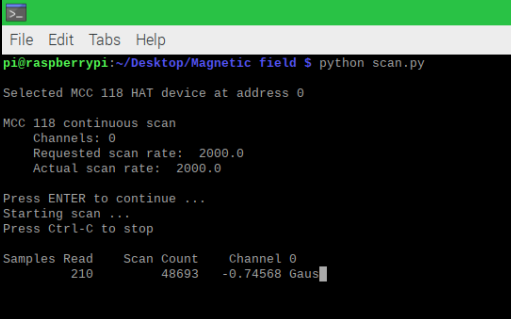
The interpretation of the display is as follows:
Samples Read is the number of samples displayed and resets back to 0 after the buffer fills.
Scan Count is the total numbers of the samples read, it does not reset when the buffer is full and continues to count.
Channel 0 is the value read by that channel, after this the following channels added later will appear.
Code
Credits
Digilent Inc
Digilent Inc., a National Instruments company, is a leader in the design, manufacture and worldwide distribution of FPGA development boards and Test and Measurement devices for both industry and education. Since our founding in 2000, Digilent has partnered with different leading semiconductor companies including Xilinx, Microchip, Analog Devices, ISSI and Texas Instruments to bring products with the latest embedded & electronics technology. Our expert team of engineers, combined with our manufacturing services and worldwide distribution has made us an ideal partner for several leading technology providers. We want to enable our partners to be successful through well designed, high quality and well manufactured hardware.
Leave your feedback...