
Lead Acid Battery Capacity Tester (updated)

Made by electrouser805
About the project
A 12 V Lead-Acid Battery is Discharged at a Constant Current (Programmable) for a Period of Time to get Terminal Voltage VS Time curve
Project info
Difficulty: Difficult
Platforms: Arduino, Atmel, Intel, Microchip, Texas Instruments
Estimated time: 2 days
License: GNU General Public License, version 3 or later (GPL3+)
Items used in this project
Hardware components


View all

Story
Yosh ! At last, finished working on this project. I have been working on this project for a while, then got bored and left the remaining work ( mostly firmware ) for a couple of months, ah ! the longest project I ever did !
; ; 1 / 6
1 / 6
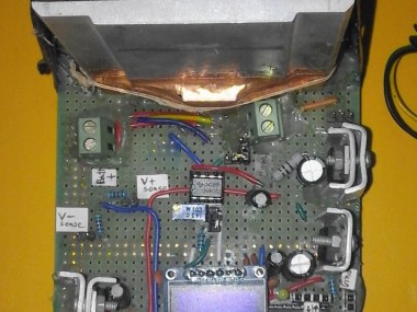
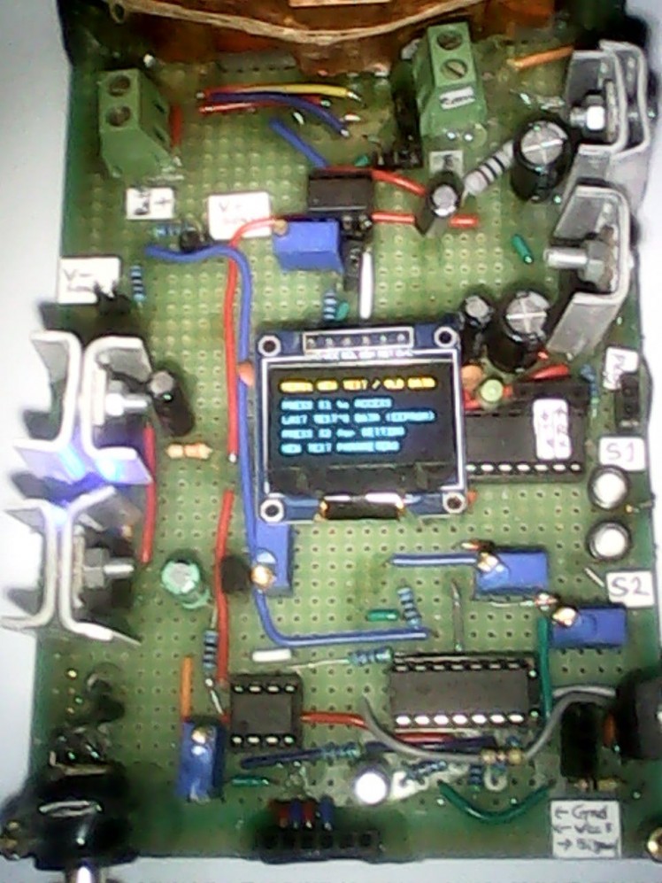
Discharge Test in Action
(Test Parameter : Discharge Current 1500 mA)
What's all this about ?
This project is about discharging lead acid battery at a constant current to measure its actual capacity.
Due to hardware and design constrain there are few limitations :
- Only 12 Volts Lead Acid Batteries up to 200Ah can be Discharge ! Because of measurement offset (to achieve better Voltage Measurement Resolution) only Voltages from 10.1 V to 14.7 V can be measured, which means any voltage below 10.1 volt will read 10.1 volt. Besides, a 12 Volt Lead Acid Battery that reads 10 volt is practically Dead !
- Current Measurement Resolution is 25 mA to cover a wider measurement range (0-13.9 A) which can be a problem for measuring very small Discharge Rate ( below 300 mA )
- Voltage Measurement Resolution is 5 mV. Measured voltages are stored in EEPROM periodically (every 5th minute) and exported through USB-Serial after the test is completed.
- Discharge Current can be (Set) Programmed by User through S1/S2 buttons and which can be any value multiple of 0.1 A (100mA) from 0.1 A to 10.0 A.
- C-Rate (which is equal to Discharge Time/Expected Test Duration) can be configured by User for 5 hrs or 10 hrs or 20 hrs. For example if a 35 Ah Battery is discharged at a C-Rate of C/10 then the Discharge Current will be 3.5 A (3500 mA) and the expected Discharge Duration should be 10 hrs.
- Test can be Aborted by user (with proper Ramp Down of Current to 0 A) by pressing S1/S2 buttons according to the instructions shown on OLED screen Menu !
- During the Test Run the OLED Display will show Test Time, Discharge Current, Battery Terminal Voltage on the screen.
- Test will stop automatically whenever Battery Cut Off (here 10.5 V) is reached or Time (=C hrs) is elapsed.
- Time keeping is done using the AVR internal Timer1 with Interrupt. S1/S2 Buttons are connected to INT0/INT1 of Atmega328 microcontroller for controlling User Interface.
How Does it Work ?
Dynamic Electrical Load
The LOAD(MOSFET+Resistor Network) through which the discharge current runs is a Programmable Active Load. It is driven such a way that a constant current flows through it regardless of the drop of battery voltage over time due to discharge !
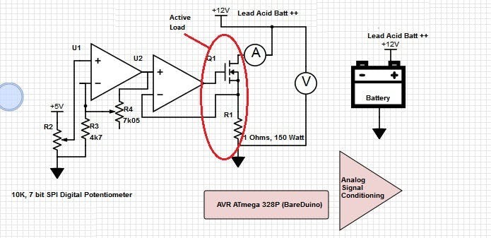
Active Load consists of a MOSFET(Q1) and High Wattage Resistors Network (shown as single Resistor R1) , the MOSFET's Drain to Source Channel acts as a Variable Resistor and the High Wattage Resistor Network has a Fixed Value Resistance (until it heats up too much).
Opamp Action
OpAmp U1 is configured as Non-Inverting Amp with DC gain of 2.5. So If we put 1 Volt on + Input of U1, it's Output will be 2.5 Volt . (Note that all the OpAmps are powered with 18.9 volt positive rail, so maximum Output for the OpAmps can be up to 17.4 volt) .
The Output of OpAmp U1 is connected to the (+)Input of OpAmp U2.
Here is a little Myth : OpAmps are Magical Electronic Beasts ( I personally prefer to call them Analog Microcontrollers ). According to the Legends of OpAmp - OpAmps will try to do anything with in their capability to keep their both (+)Input and (-)Input at same voltage level. No Current Flows In or Out of the OpAmps Input pins >So, OpAmp U2 will try to keep its both (+)Input and (-)Input at 2.5 Volt. But, Wait ! The (-)Input of U2 is directly wired to 1 Ohms Resistance R1, right ? Now, to maintain 2.5 volt there, according to Ohms Law V=IR, 2.5 Amp current must flow through the Resistor R1. There is now way the OpAmp's Input will deliver this current (the Legend, remember ?). So, what's going on ?
This is where the OpAmp U2 will Output a Suitable Gate Driving Voltage ( which is close loop stuff, Pole/Zero control, maybe PID stuff - who cares ! ) Such-A-Way that the MOSFET Q1 turns on partially, operates like a voltage controlled current source.
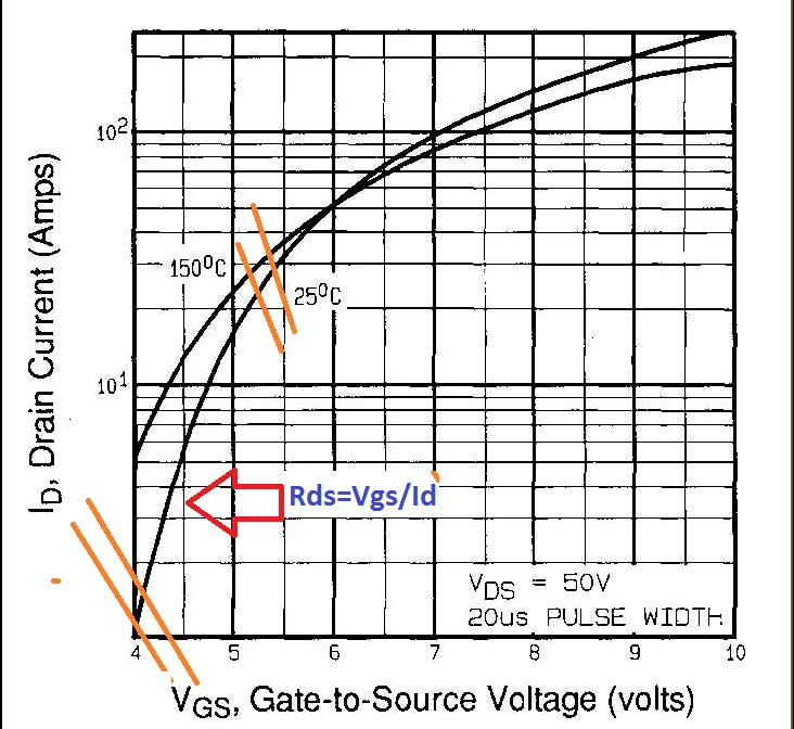
The Drain to Source Channel of MOSFET Q1 will allow to flow 2.5A current, which will also flow through the Resistor R1 to Ground, resulting a 2.5 Volt on the (-)Input of the OpAmp U2 . (This Stuff is Deep, I am only scratching the surface !)
The OpAmp will Automatically adjust its Outputs to maintain this state.
Arduino Action
Now, the Resistor R2 is a Digital 10K Potentiometer (MCP4131), the Resistance can be programmed through SPI communication. The (Ar)Bareduino does this job and other tasks like OLED Display driving, taking User Input, measuring Current and Voltage from sensors using ADC.
Power Rails
There are few power rails on this device:
- 5.0 Volt for Digital Systems (Arduino(MCU), OLED Display, DigiPot, Current Sensor)
- 12.0 Volt for Heat Sink Cooling Fan
- 18.9 Volt for OpAmps
- 9.35Volt and 1.8 Volt Precision Reference Voltages for differential measurement and Analog Signal Conditioning before ADC conversion .
Results
So, what is the outcome of this kind of test ? First of all, we will get a time vs Vbatt curve, which can be used for performing partial discharge capacity estimate in future tests.
How do we get the capacity of the battery ? Say, you have taken a 100 Ah Battery and started the test with a discharge current of C/10 (or 10 Amp),. If the Battery had 100% of its rated capacity, after 10 hrs the battery voltage should be above 10.50 volts. But lets say, the battery reached 10.50 volts after 9 hrs 30 min, so the battery's current capacity is 95 %.
Check this test report : Test Report
Scope of Improvement
- Battery capacity strongly depends on ambient temperature. This device is expected to operate 25'C +/- 5'C ambient temperature condition. Design can be improved by using Temperature Compensation (LM75 will do), which will allow the device to measure capacity in more chiller or more warmer weather.
- Addition of pH meter to measure acidity of electrolyte and calculating Specific Gravity level from fully charged to fully discharged will allow further data for analysis.
- Instead of discharging, measuring capacity while charging kind of approach is a better and more reasonable way to do this.
Check the links and documents for further reading :
(Following links and docs are properties of respective owners, given for reference only)
Schematics, diagrams and documents
Code
Credits
Related products


Leave your feedback...