
L293d Motor Driver Shield With Arduino

Made by rachana-jain / Robotics
About the project
In this tutorial, you will learn about how to use an L293D motor driver shield with Arduino to control the speed and direction of rotation of motor
Project info
Difficulty: Moderate
Platforms: Arduino
Estimated time: 2 hours
License: Apache License 2.0 (Apache-2.0)
Items used in this project
Hardware components

|
Jumper wires (generic) | x 1 | |
|
|
Solderless Breadboard Full Size | x 1 | |
|
|
LCD 16x2 | x 1 | |
|
|
POT 10kohn | x 1 | |
|
|
Push button | x 1 | |
|
|
DC motor | x 1 | |
|
|
L293D Motor Driver Shield | x 1 | |
|
|
Arduino UNO | x 1 | |
|
|
servo motor | x 1 | |
|
|
stepper motor | x 1 |
View all
Story
The L293D Motor Driver Shield is one of the most versatile shields for driving DC, stepper, and servo motors with Arduino. This shield can control up to 4 DC motors, 2 stepper motors, and 2 servos simultaneously.
In this tutorial, you’ll learn how to interface the L293D Motor Driver Shield with an Arduino UNO to control speed and direction these motors.
What is L293D Motor Driver Shield?
The L293D motor shield acts as an interface between Arduino and motors. It uses two L293D H-Bridge ICs to drive motors bidirectionally. Each IC can control two DC motors or one stepper motor. Together, the shield supports:
- 4 DC motors
- 2 stepper motors
- 2 servo motors
It simplifies wiring and makes motor control plug-and-play for robotics, vehicles, and automation projects.
Features of L293D Motor Driver Shield
- Controls 4 DC motors (bidirectional).
- Supports 2 stepper motors (unipolar/bipolar).
- 2 servo motor connections (using Arduino pins 9 & 10).
- Onboard 74HC595 shift register for pin saving.
- Separate supply options for logic and motor power.
- Onboard reset button, power LED, and pull-down resistors.
L293D Motor Driver Shield Hardware Overview
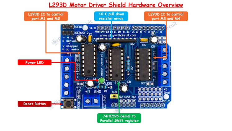
L293D IC: At the core of the motor driver shield are two L293D ICs, each a 16-pin dual H-bridge driver. One IC can drive two DC motors or one stepper motor, and with two ICs on the shield, it supports up to four DC motors or two steppers. The first L293D chip controls ports M1 and M2, while the second chip controls ports M3 and M4.
74HC595 Shift Register: The shield also includes a 74HC595 8-bit shift register, which expands the number of control pins available. Its eight parallel outputs are connected to pins 2, 7, 10, and 15 of both L293D ICs, enabling efficient direction control without occupying too many Arduino pins.
Reset Button: A convenient reset button is provided on the shield. This is directly connected to the Arduino UNO’s reset line, making it easier to restart the board without removing the shield.
Power LED: The shield features a power indicator LED that lights up when the motor power supply is connected and available, ensuring quick status checks.
Resistor Array: A built-in 10kΩ pull-down resistor is added to hold motor control pins low at startup. This prevents unwanted motor movements when the board is powered on.
L293D Motor Driver Shield Pinout
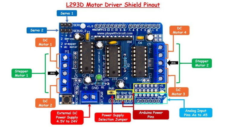
The L293D motor driver shield uses two L293D ICs, each offering two output channels. These channels are accessible through four screw terminals labeled M1, M2, M3, and M4. You can connect up to four DC motors to these terminals, with supported operating voltages between 4.5V and 24V. Each channel can provide 600 mA of continuous current, with short bursts reaching up to 1.2A, depending on the motor’s requirements and the power supply. The ground terminals are shared between M1–M2 and M3–M4.
Stepper Motor ConnectionsThe shield also supports the use of stepper motors. One stepper motor can be connected to the M1–M2 pair, while another stepper motor can be connected to the M3–M4 pair. This enables you to control two stepper motors simultaneously, making the shield a good option for projects requiring precise motor movements such as CNC machines or robotic arms.
Servo Motor ConnectionsFor servo motors, the shield provides two dedicated three-pin headers. These headers allow direct connection of two servo motors, identified as Servo 1 and Servo 2. Servo 1 is controlled through Arduino’s PWM pin 10, while Servo 2 is controlled through PWM pin 9. Both servos draw power directly from the Arduino’s 5V line. Since this can put a strain on the onboard regulator, the shield includes a 100 µF capacitor to stabilize the supply voltage. However, it is still important to ensure your servo motor does not exceed the Arduino’s current capacity.
Power Supply and Jumper SettingsThe shield supports motor supply voltages ranging from 4.5V to 24V, and it can be powered in two different configurations. In the single power supply method, both the Arduino and the shield are powered from the same DC source, typically connected through the Arduino’s DC jack. In this case, the power selection jumper on the shield should remain in place. For the separate power supply method, the Arduino is powered via USB or DC jack, while the shield is powered using an external DC supply connected to the EXT_PWR terminal block. In this setup, the power jumper must be removed to prevent short circuits between the two supplies.
Arduino Power PinsThe shield also makes Arduino’s standard power pins easily accessible. These include the 5V, GND, and Vin pins. The pin labeled “9V” on some shields is actually the Vin pin, which outputs the same voltage supplied to the Arduino’s DC jack. When the jumper is connected, this Vin pin is internally linked to the motor supply line of the L293D IC.
Analog Input PinsFinally, the shield provides access to all six analog input pins (A0 to A5) of the Arduino. These pins can be used for connecting sensors, potentiometers, or other analog devices. Additionally, they can also be configured as digital I/O pins if needed, giving you extra flexibility when building your projects.
Wiring of DC motor with L293D shield and Arduino UNO
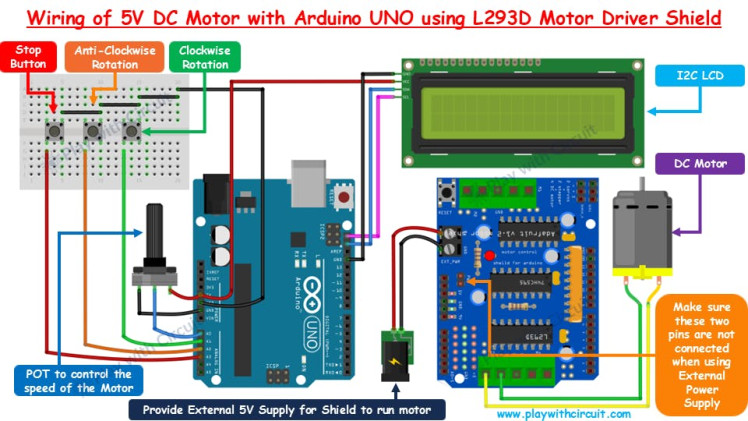
In this setup, the L293D shield is mounted on top of the Arduino UNO, but in the wiring diagram it is shown separately for clarity and to illustrate the button and potentiometer (POT) connections.
The POT is connected to A0, with its middle pin going to A0 and the other two pins to VCC and GND. This allows the voltage at A0 to vary, which is then used to control the motor’s speed—the higher the voltage, the faster the motor runs.
Since the shield already occupies D3 to D12 for motor control, and D0 and D1 are reserved for serial communication (while D13 is tied to the onboard LED), the only unused digital pin is D2. To add more inputs, the analog pins A1, A2, and A3 are repurposed as digital pins. These are connected to push buttons: A1 controls clockwise rotation, A2 controls anti-clockwise rotation, and A3 stops the motor.
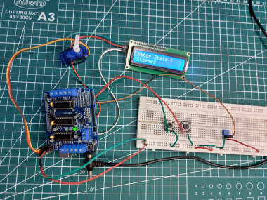
A 16×2 I2C LCD is connected to the Arduino’s SCL and SDA pins to display the motor’s speed and direction. The 5V DC motor is connected to port M3 of the shield, and an external 5V supply is provided through the EXT_PWR terminal on the shield.
⚠️ Important: The PWR jumper must be removed when using an external supply, otherwise it may cause damage.To learn how to control Servo, and Stepper Motor checkout complete tutorial: How to Control DC, Servo, and Stepper Motors with L293D Motor Driver Shield & Arduino
Code
Credits
Related products


Leave your feedback...