

Jumperless

Made by ArchiteuthisFlux / Lights / Productivity
About the project
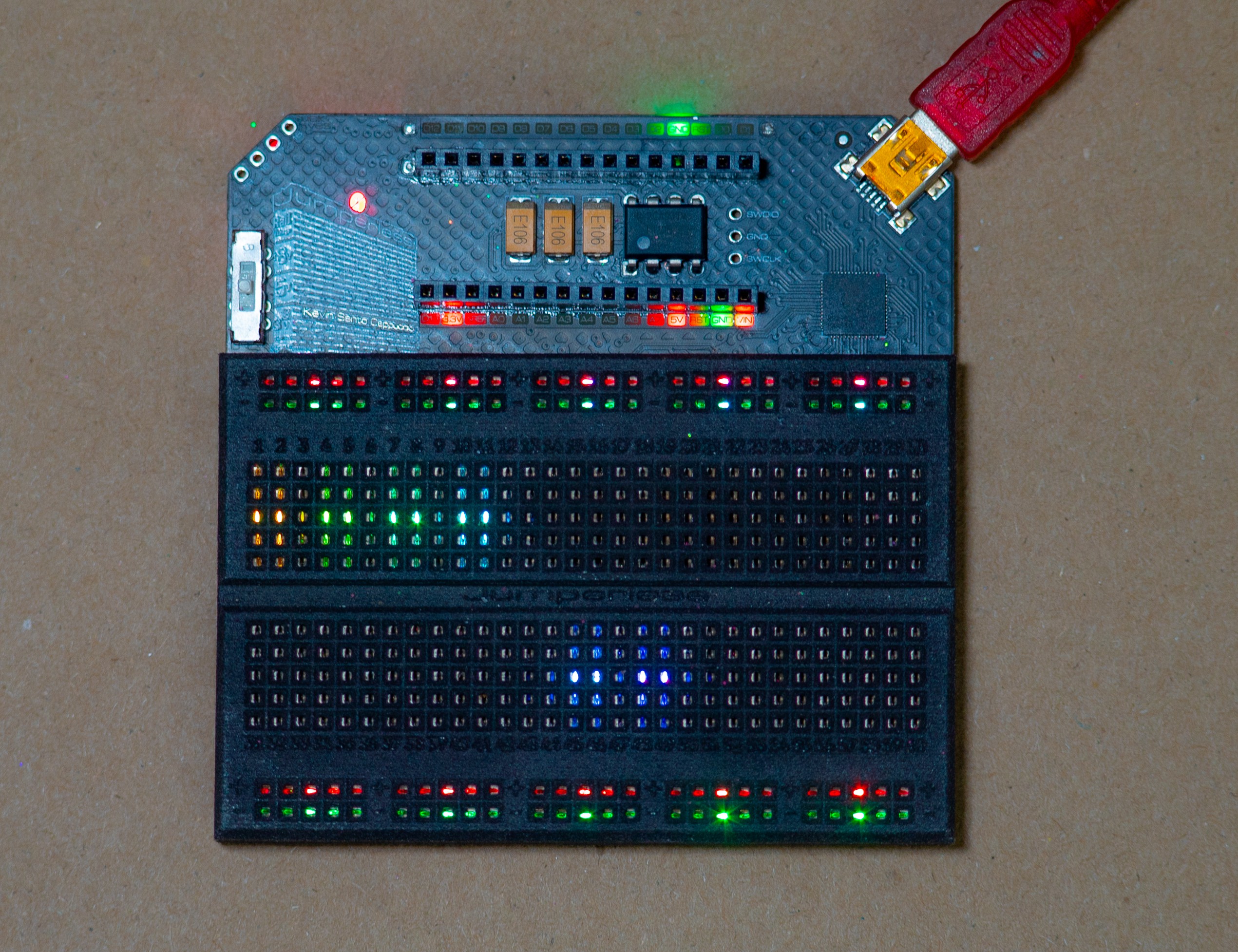
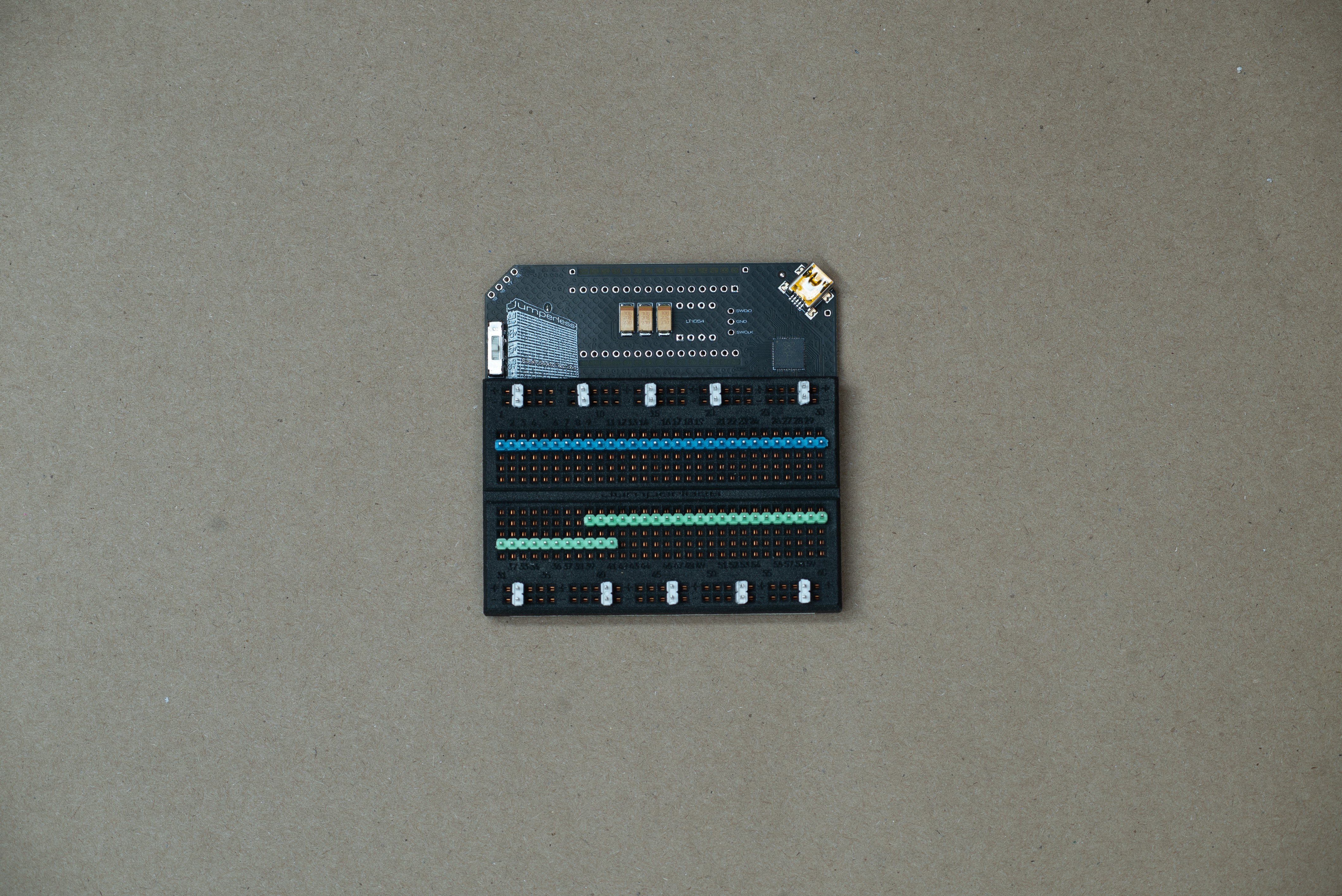
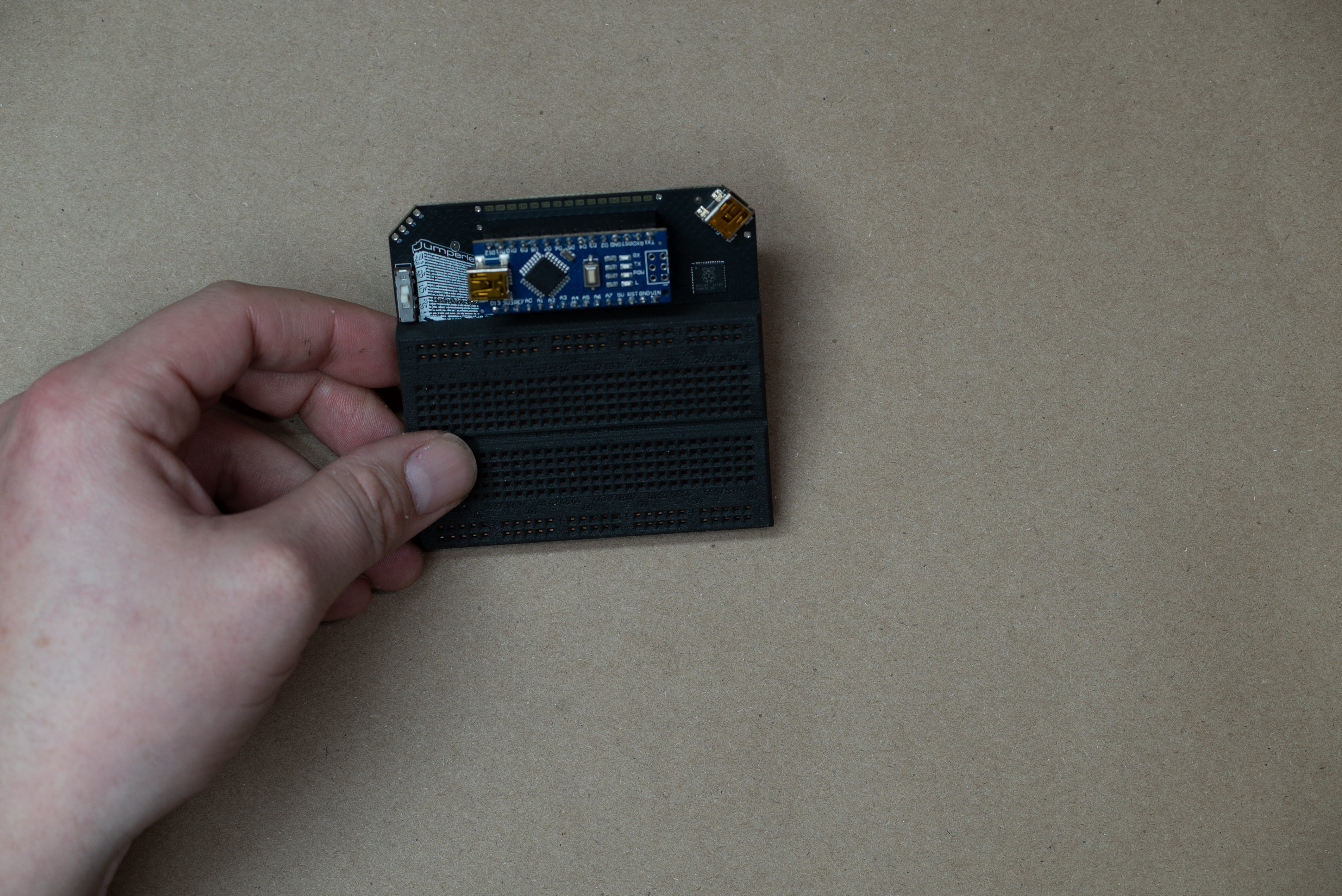
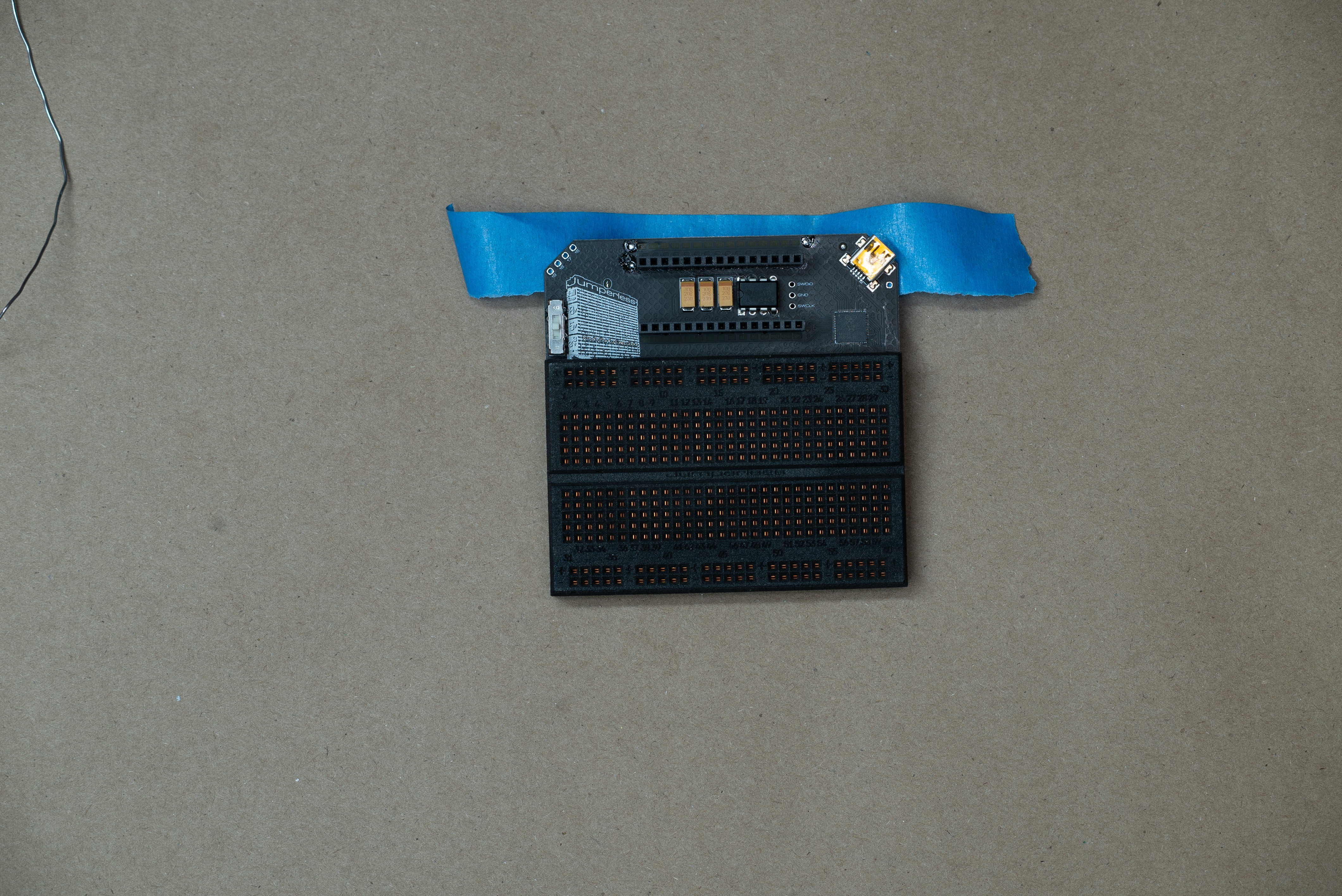
A jumperless (solderless) breadboard
Project info
Difficulty: Easy
Platforms: Arduino, Firmware Modules, Raspberry Pi, CircuitPython
Estimated time: 2 hours
License: GNU General Public License, version 3 or later (GPL3+)
Items used in this project
Hardware components

View all
Software apps and online services
Story
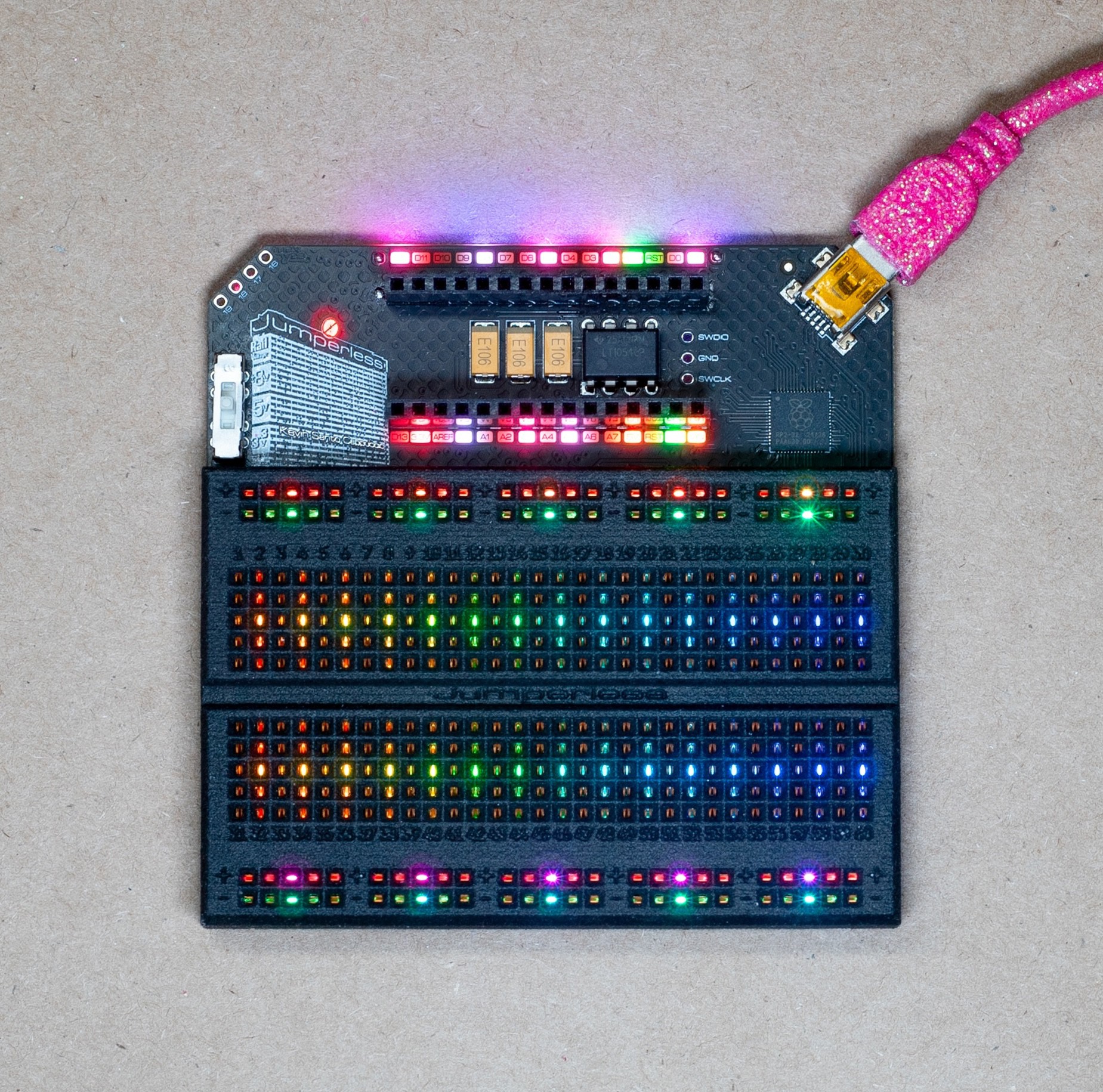
Jumperless
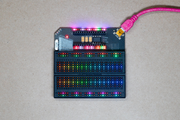
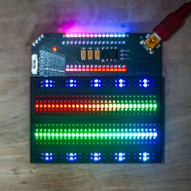
Using a bunch of analog crosspoint switches wired together into one bigger switch, Jumperless makes real, fully analog hardware connections between any points on the board or the Arduino Nano header at the top via serial, instead of needing to use jumper wires.
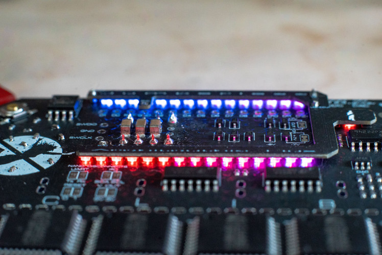
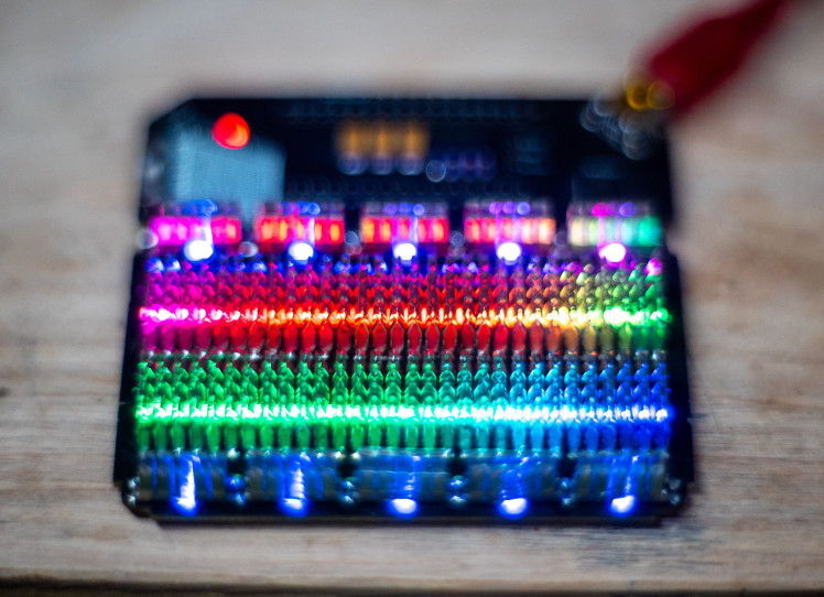
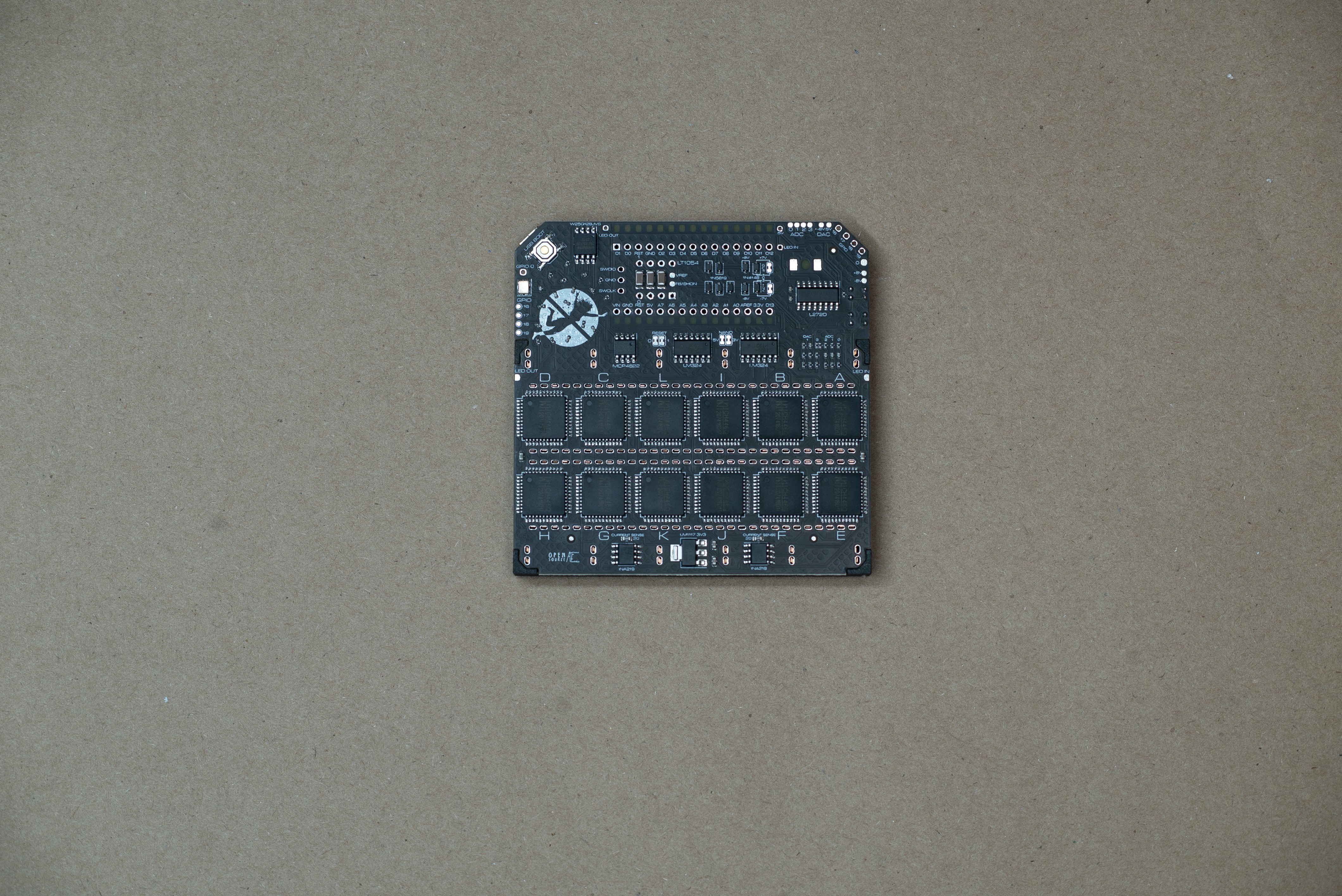
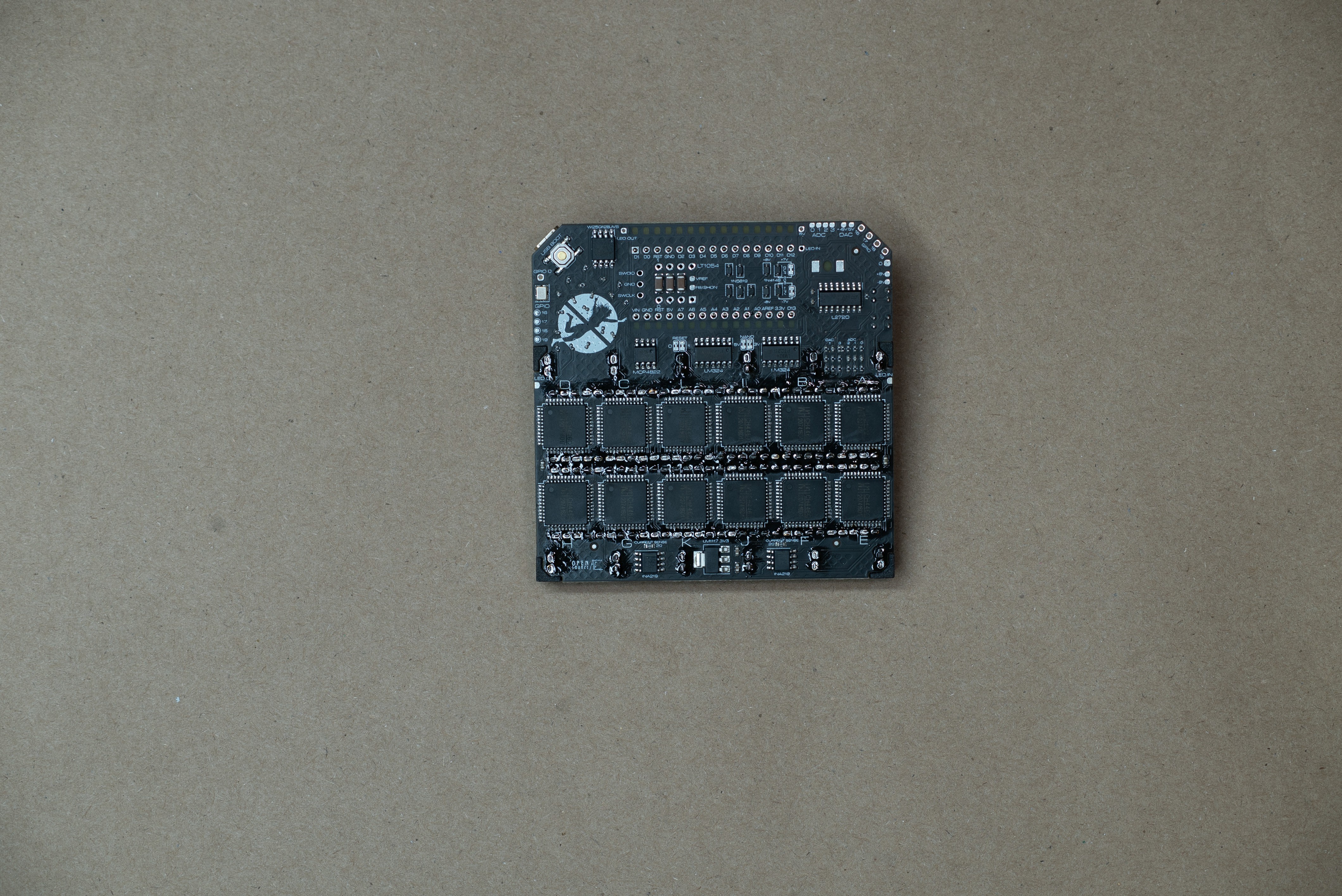
Jumperless also has a ton of voltage/current sensing so the RGB LEDs underneath each row can show a ton of information about what's going on with your circuit. It has 2 buffered DACs (0-5V and ±8V), 4 buffered 12-bit ADCs (3 are 0-5V and 1 for ±8V), 2 INA219 current/voltage sensor ICs, and 5 GPIO that can be routed to anywhere on the breadboard or the Nano header.Use it to probe the pins on an unknown IC, or for some automated fuzzing, or to read/write EEPROM chips, or to help guide you through converting a schematic to a real circuit, or do whatever the hell you want with it.
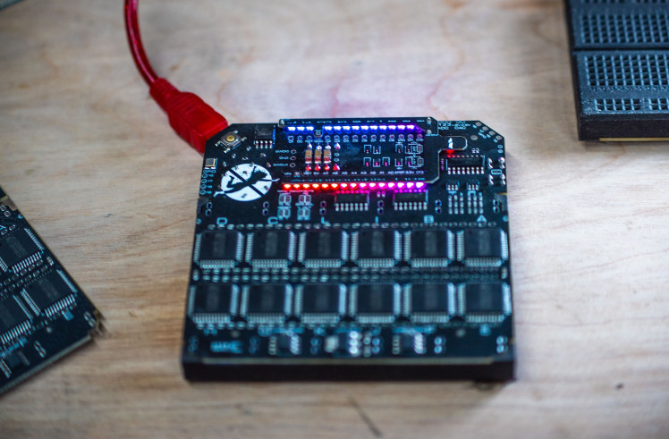
Controlling the thing
Currently, the best way to make connections is using Wokwi while running the Jumperless Wokwi Bridge app on your computer. It's a Python script and command line interface that automatically pulls any changes you make to your Wokwi project and sends them to the Jumperless.
Here's a video of me connecting an OLED display to an Arduino
It also passes through all the serial communications to and from the Jumperless so you can use the text-based menus to do things like running the wave generators, measuring current/voltage, and looking debug output on the Jumperless directly at the same time.
Pretty soon there will be an Arduino Library where you can make connections and measure stuff with an API that will look something like jumperless.connect(row1, row2); or jumperless.measureVoltage(row); that can either be run on the Arduino Nano (sending commands via UART to the RP2040) or the Jumperless itself.
Hopefully this will allow people to write cool stuff for the Jumperless to do that I haven't even thought of and wouldn't be possible on a regular breadboard.
Also there will be a Python Module that does the same stuff as above, which can either be run in an onboard MicroPython interpreter or on a computer.
Here's another video of me using the Jumperless to figure out the pinout of an LED matrix. I'm actually not faking it in this video, I couldn't find a datasheet.
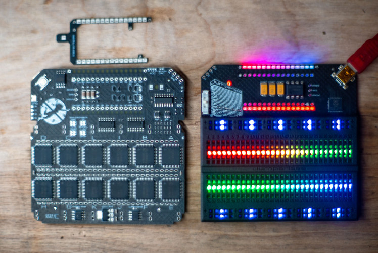
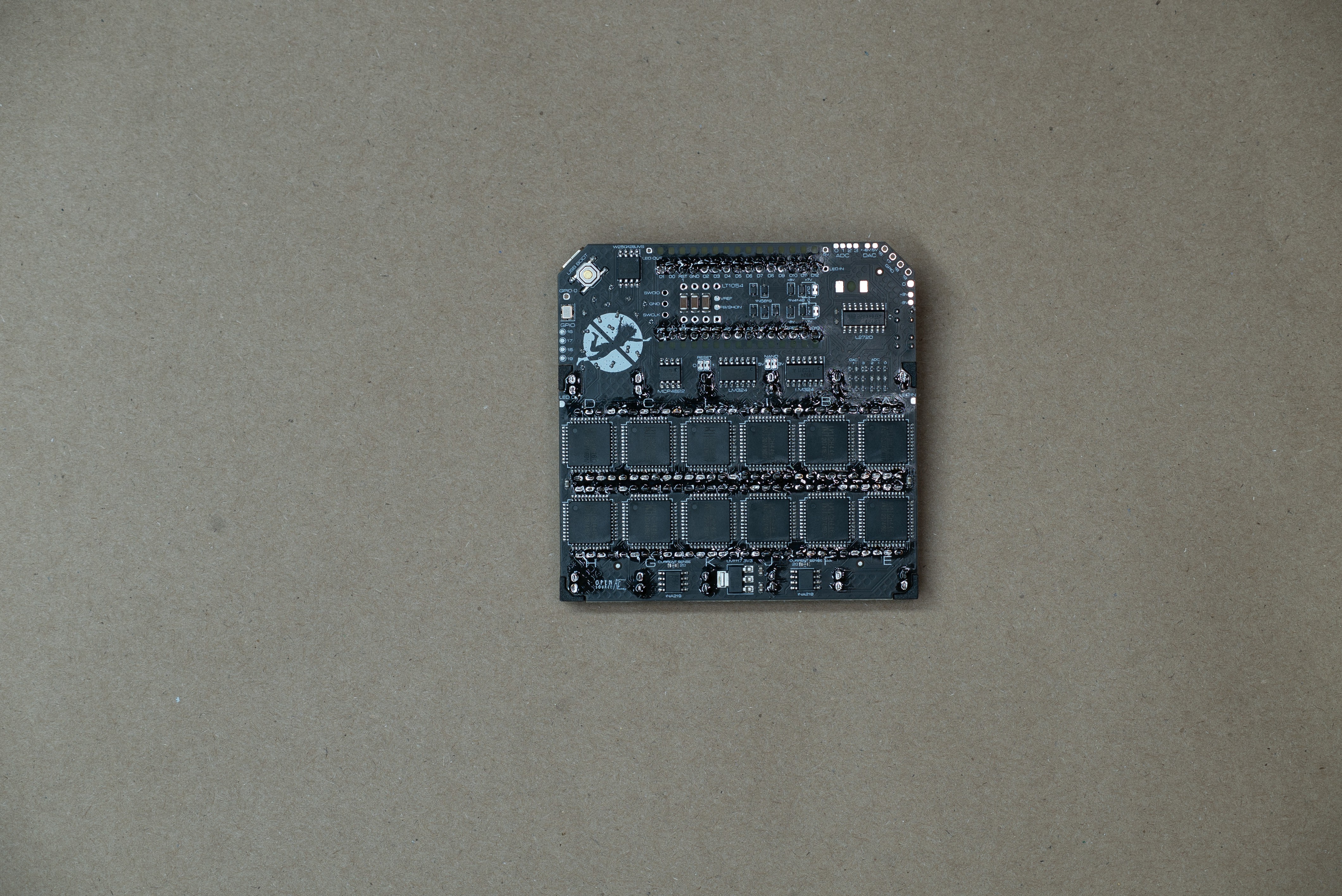
Firmware and stuff
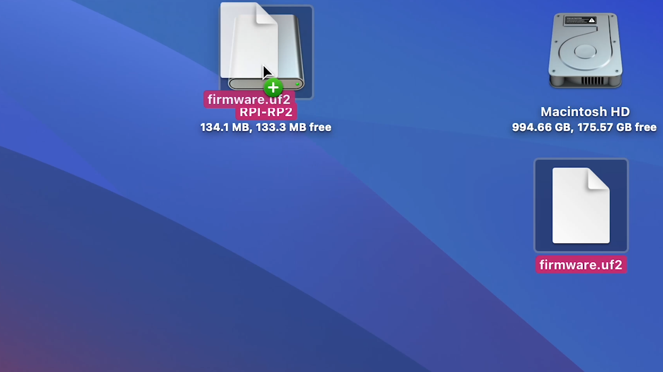
The Jumperless is controlled by an RP2040 and can be programmed exactly like a Raspberry Pi Pico. I spend every waking second of my life working on the firmware so there will be frequent updates. There are prebuilt UF2 files on Github under Releases, so whenever there's an update, just hold the USB BOOT button while plugging it into your computer (with the included pink glittery USB Mini cable,) then drag that UF2 file into the drive that pops up and you're good to go.
The whole thing is open source so you can also edit/fix the firmware however you like (and please submit a pull request on Github to share your fixes)
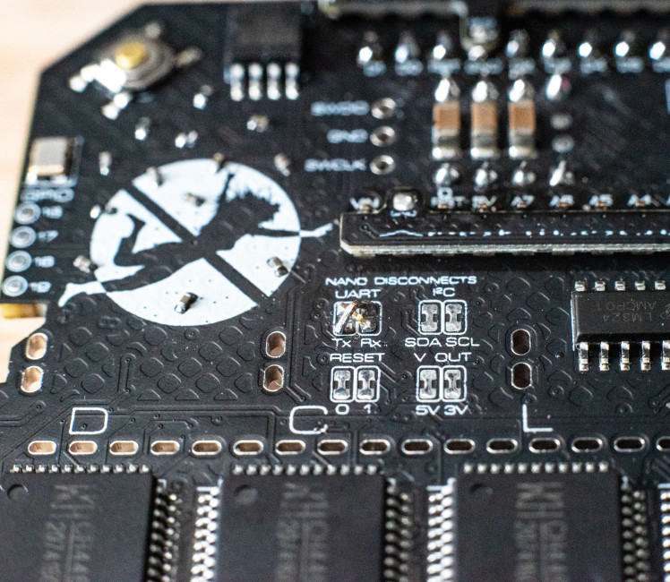
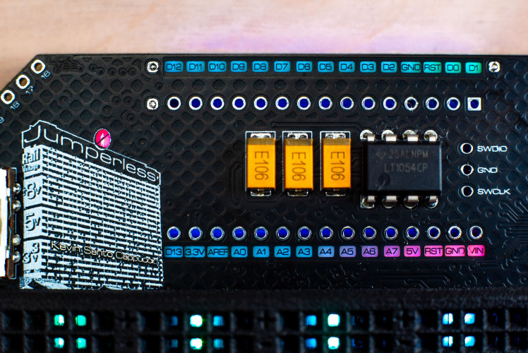 DACs and Revisions
Currently, the ones available are Revision 2, the only major difference between Rev 2 and the soon-to-be-available Rev 3 are the Digital Analog Converters. If you're an audio person that might want to use this thing as a eurorack module or something involving generating audio, I recommend you wait for Rev 3 to be available in a couple weeks. Here's why:
Revision 2 uses 2 MCP4728 12-bit I2C DACs, which work great for setting voltages to be used as an adjustable power supply, but I2C isn't fast enough to send clean waveforms above ~100Hz.
Revision 3 now uses a single MCP4822 2 channel SPI DAC, which is fast enough to make waveforms well above 400KHz. So you could feasibly use the onboard DAC as a Max8 or plugData output, and route the audio output to the breadboard and mess with it in hardware and even send it back in as an input. The software to do that hasn't been written yet but with the upcoming Python Module and Arduino API, it shouldn't be too difficult pull off.
Both of these revisions have their DACs buffered through an LM272D High Power (1A) op amp. Obviously 1 amp would blow this thing up, the power supplies couldn't handle it, and it would go way over the current limit for the crosspoint switches. But the outputs of the buffered analog voltages are broken out to pads in the top corner, so you could drive a smallish speaker directly form that if you wanted to.
The +-8V DAC output is hardwired to one of the 2 INA219 current/voltage sensors so you can always see how much current is being drawn. The other INA219 is routable anywhere on the breadboard.
If you blow something up on this board for whatever reason, just let me know. I'd be happy to repair it for you for free or walk you through the repair and send you the parts.
Power supplies
The switch on the upper left controls the rail voltages, if you look at the side of the building in the logo, you'll see the settings; +-8V, 5V, and 3.3V. If you set it to +-8V, the top positive rail will be ~+8V and the bottom positive rail will be ~-8V. Otherwise, they will both be the same, either 5V or 3.3V. The negative rails are permanently tied to Ground.
Temper your expectations
Although Jumperless is made with love, it's not a precision instrument, the connections it makes go through CH446Q crosspoint switches and do have some resistance, about 75 Ohms total for a connection and resistance is matched to within 5 ohms for every connection. It sounds like a lot, but in practice it doesn't seem to have a noticeable effect on most circuits that one would build on a breadboard. It also sort of acts like a current limit to keep you from accidentally frying stuff.
If you want to get the resistance lower, you can make redundant connections to halve it each time (running that 75 Ohms in parallel with another 75 Ohms.)
Also temperature apparently has an effect on Ron, the colder it gets the lower the resistance. So if you care, turn the LED brightness down (the generate a good deal of heat) or put the whole thing in a tray of liquid nitrogen.
Worst case, it's still a breadboard and although it's called Jumperless, that's not a rule. You can run jumpers the old fashioned way.
There's also a maximum rated current for the crosspoint switches, it says 15mA per connection and 100mA per chip. I have run 200mA through a single connection for a few minutes without issues, but of course be aware of that.
I'm giving you permission to take the Absolute Maximum Ratings for the CH446Q with a grain of salt. If you fry one, I'll repair it for free. The chips are super easy to swap out with a hot air gun. If you think you're going to fry these chips regularly (it's actually surprisingly hard to do), and have access to a hot air station, let me know when you place the order and I'll throw in a few extra CH446Qs in the box so you can replace them yourself.
For firmware, occasionally there are some arrangements of connections that the pathfinding code trips up on and can't find a path for. If that happens to you, please screenshot the connections and send it to me or open a Github issue. I can usually fix those issues within a day, but the hard part is finding those arrangements that cause issues.
One day when I decide to make my own custom silicon for this, it can be made with beefy power MOSFETs to get it close to a perfect connection. But for now, I have to work with ICs that already exist.
Just for fun, here's a crazy sped-up video of me routing this board:
If you're a l33t hacker, you can even type in netlists by hand. For example,
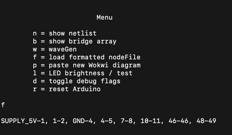
will make this happen:
So you can easily write any script you like to make connections this way.
You mean an FPGA?
No, not at all, shut up. I could go on forever about the differences, but the main thing is that FPGAs are really sensitive to input voltages and really only do digital signals. Also FPGAs don't actually route signals, internally they're a grid of lookup tables that do logic operations. So a signal coming in isn't really "sent through" so much as it's copied with a logical NOTNOT (unchanged) gate, that's great for combinatorial logic, but not for analog stuff.
Also quickly throwing together a breadboard circuit in an HDL would take ungodly skills.
Doom and Some Other Less-Trivial Demos
A lot of these shots will be cut into the Hackaday Prize entry video, but I'm gonna post them here anyway so I don't feel like I've wasted time making these if I decide some of them don't fit.
Doom Over a Jumperless
Doom is the most click-baity demo you can do. And I support it (even though I suck at actually playing Doom)
Someone on Twitter asked if the crosspoint switches would interfere with fast data signals. The answer is no, they won't, they're rated to 50MHz at 3dB rolloff. The physical breadboard will have a much larger effect at those frequencies, so if it works on a regular breadboard, it should work on a Jumperless (wrt frequency, current and voltage have their own limits).
This is the awesome project doom-nano which is stripped down enough to run on an ATMEGA328P at ~15 fps. Note that the enemies don't die when I shoot them, that hasn't been implemented yet.
The nerd-sniper who got me actually was asking about SPI displays, I didn't have a Arduino Nano ESP32 at the time, but I will today (thanks Amazon). So expect a demo of real doom running on a color display soon.
16x2 LCD
And my video light Fuck mask gets its time in the spotlight.
Making this one revealed a bug in the routing code here it wasn't checking the other end of the "bounces" in certain arrangements. So yeah, 2 days of debugging for a 22 second video, that's approaching Kubrick's shooting-to-runtime ratio.
Some 7400-Series Logic Stuff
Here I threw together a random logic circuit with the chips I had laying around, and used a 555 as the clock source. Near the end, I take out the 555 and use the Jumperless's DAC making a square wave as the clock. Which might be useful if you're building just part of something and you don't want to screw around with the clock source.
There's a simple text-based wave generator menu that I'm using to control the frequency and stuff. It looks like this.
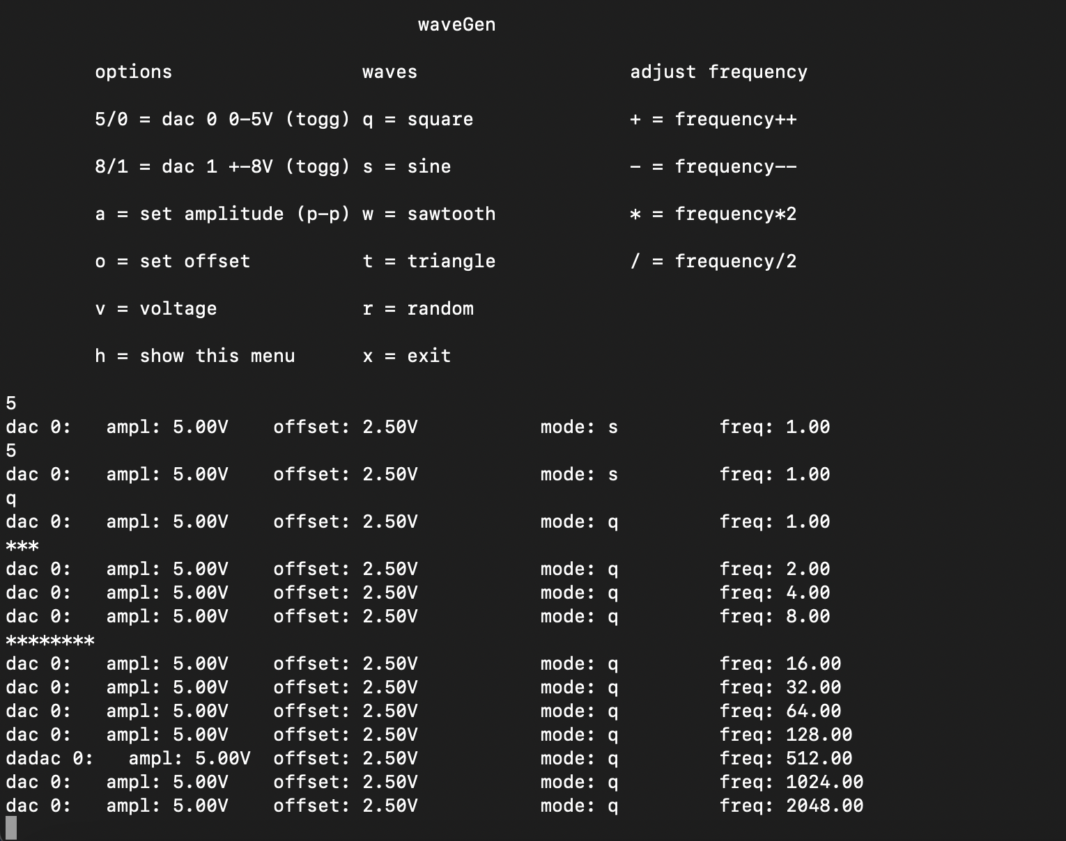
On the Wokwi project I had a potentiometer connected to the blue clock line, that's what tells the Jumperless that I want a DAC connected there.
This is the same circuit again:
Magic Flames Released
This is the silly intro shot, same circuit as above (and part of it is redundant).
Obviously, circuits don't blow up like that when you cut one wire. So let's look behind the curtain and see what I did
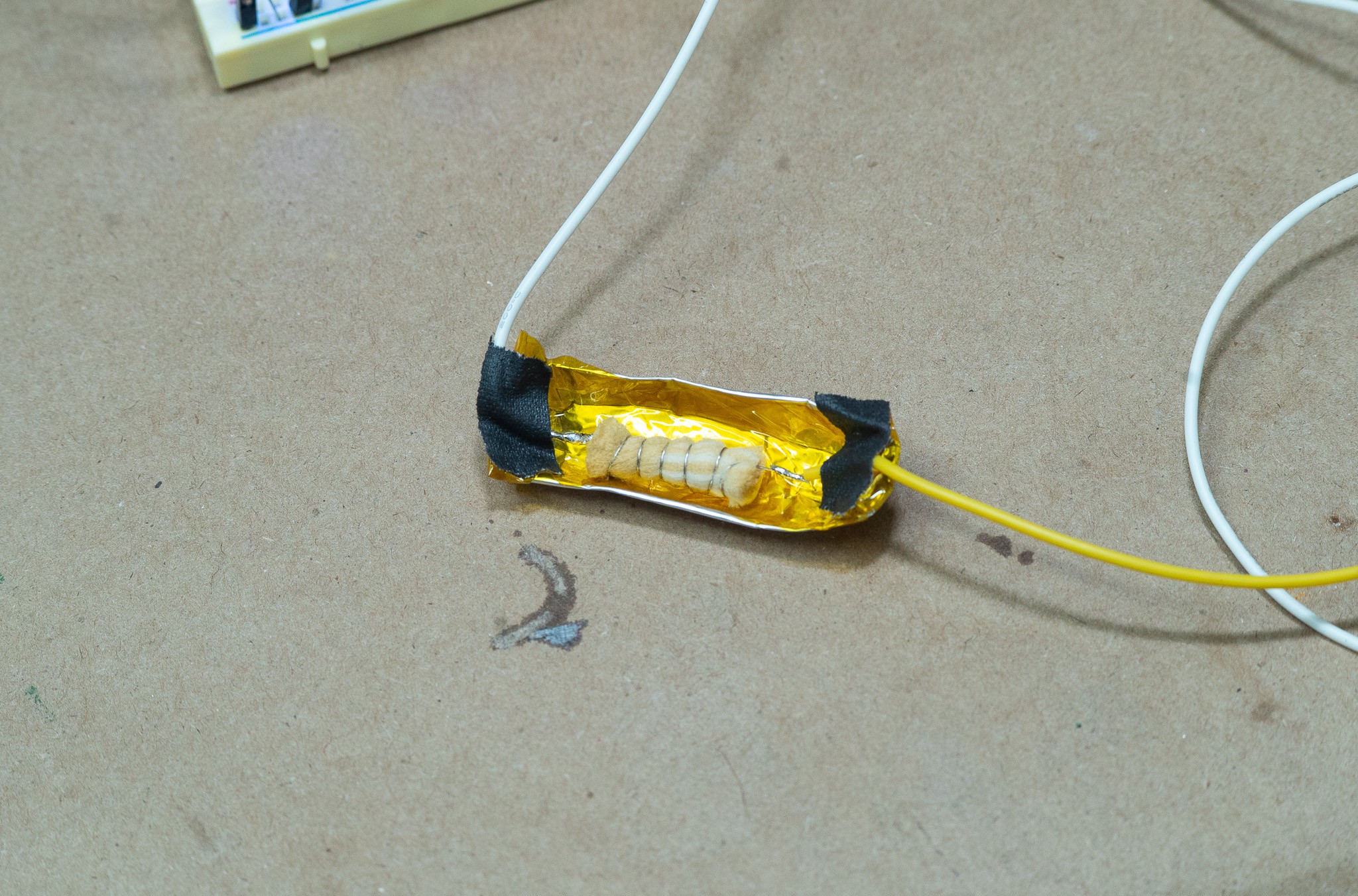
It's cigarette filter wrapped in NiChrome wire and submersed in a foil tray filled with vape juice hidden behind the breadboard then hooked up to a big 12V lead-acid battery when I wanted it to go off. I'm actually just cutting the 5V power in the video.
This is what it looked like afterwards

Ha.
I also tried just cutting 2 jumpers connected to the leads of the lead-acid battery, but the sparks weren't dramatic enough and too quick to be shot on video.
Another attempt was made by emptying out the powder from a bullet and igniting it, but modern smokeless powder is, well, smokeless. Like really surprisingly so. I even mixed it with sugar and Ammonium Dichromate but it never really looked right. So vape juice it was!
Crosspoint Superzoom
This is just to give people a but of an understanding of what's going on inside a crosspoint switch. Not really a demo, but it was made so people understand that the Jumpeless isn't reading and simulating your signals, just passing them through an analog CMOS switch.
If you want to play with that crosspoint demo in Falstad, here's the link to that circuit.
And the transistor-level analog CMOS switch is here.
Rail Selector Switch
This is a fun little shot of the supply rails being switched in stop motion.
Anyway, I think that's all the video I have for now. But stay tuned for the Hackaday Prize entry video where I cut all this together and talk at you.
If you want a deep-dive into how all the code works, there are a series of project logs on Hackaday that will walk you through how it works
Part 1 - The Code
Part 2 - Pathfinding
Part 3 - Driving the CH446Qs
Part 4 - Picking Colors and Putting Them On Your Retinas
Kit Instructions
If you get a Jumperless Kit (or order your own boards with SMD parts assembled)
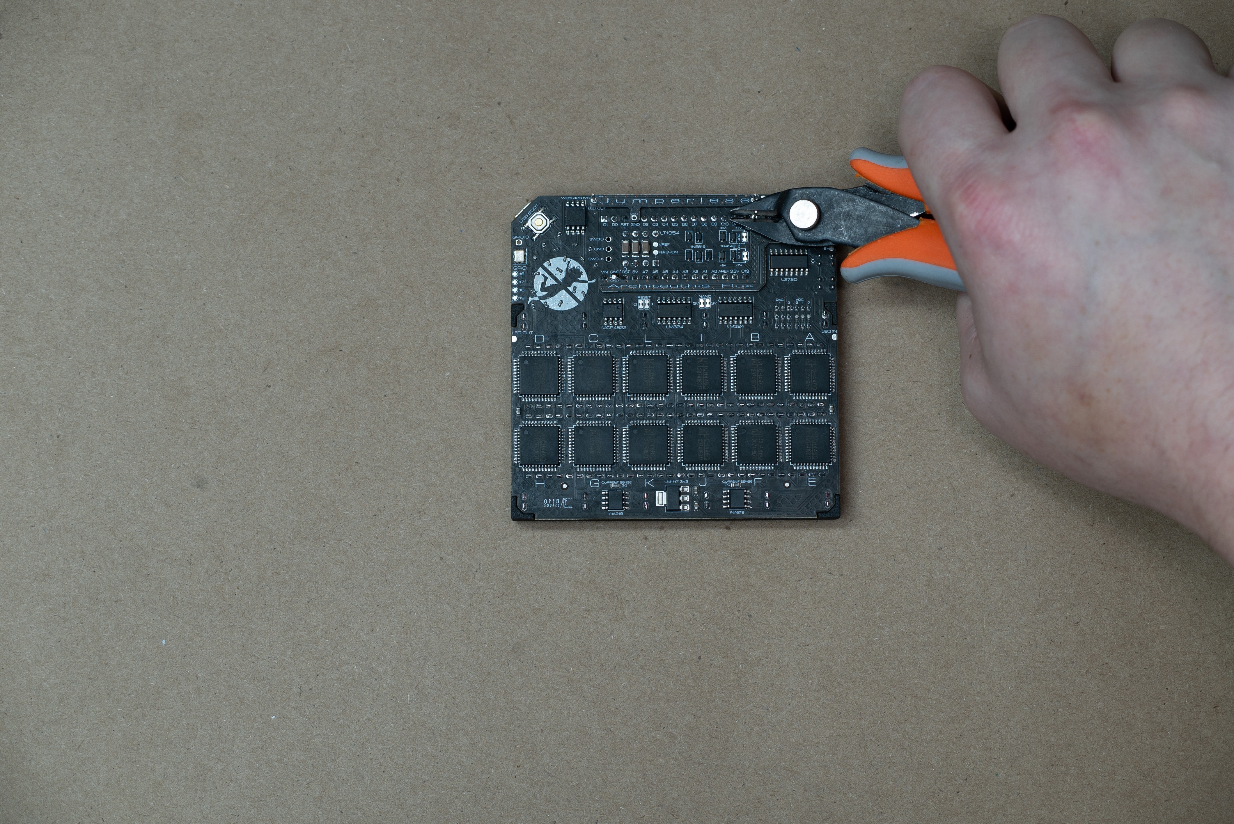
The assembly is pretty easy, it's all through hole stuff. Hence marking this project as "Easy" and "2 Hours." Obviously if you're doing all the SMD stuff yourself it will take quite a bit longer.
Here's a montage of all the steps to give an overview of what you'll be doing
If you've gone through the trouble of ordering your own boards and everything, I'd be happy to send you a free set of spring clips, which is the only part with a huge minimum order quantity and having them made was a whole thing.
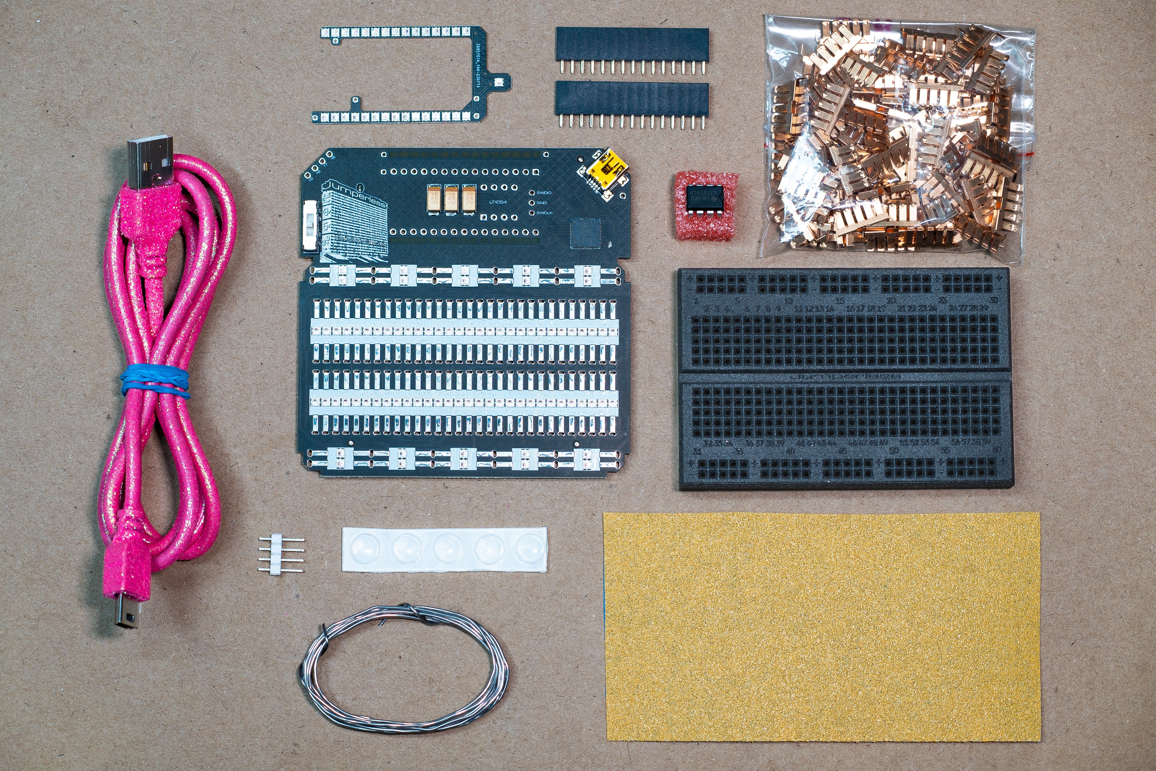
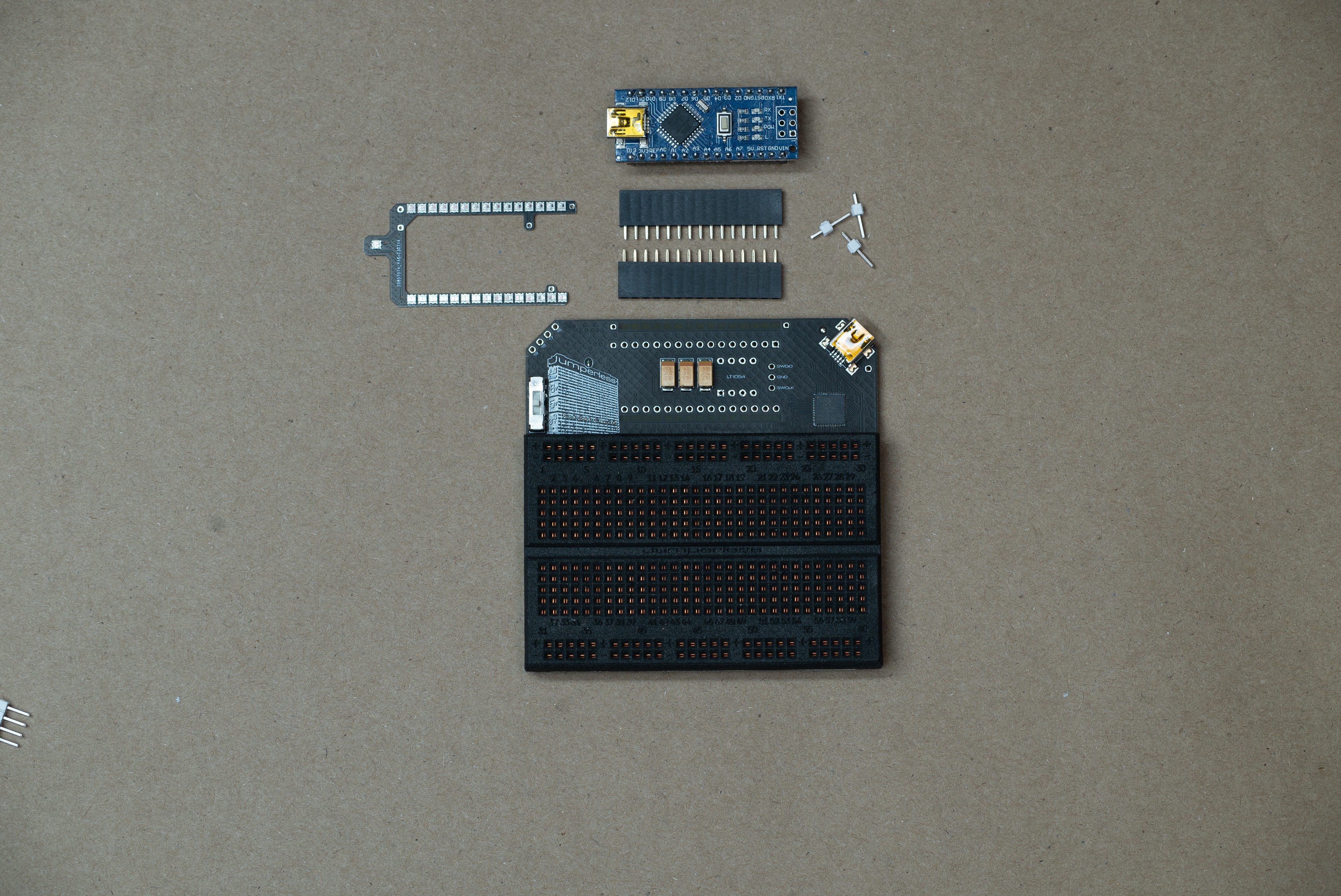
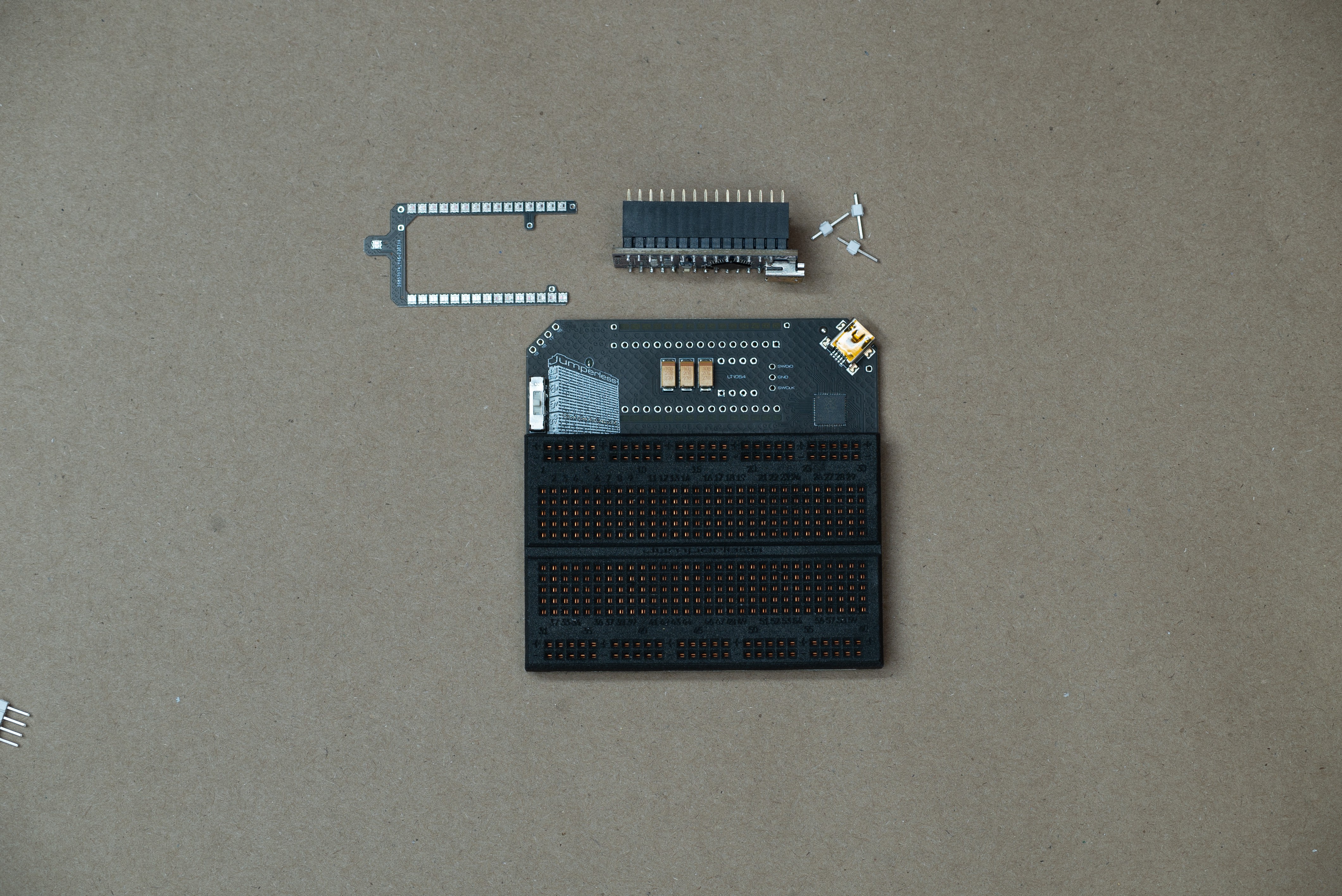
Your kit will come in ~7 parts:
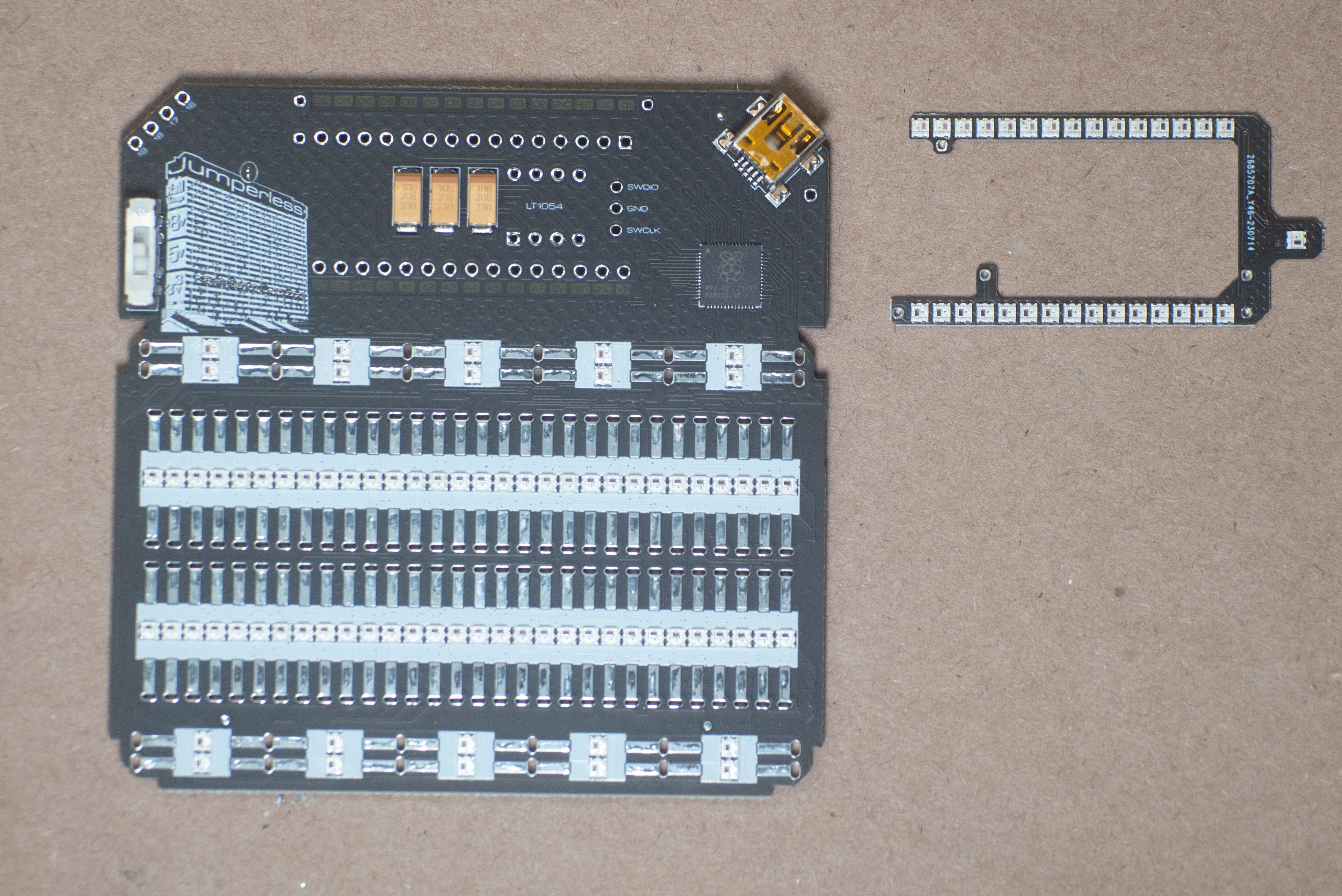
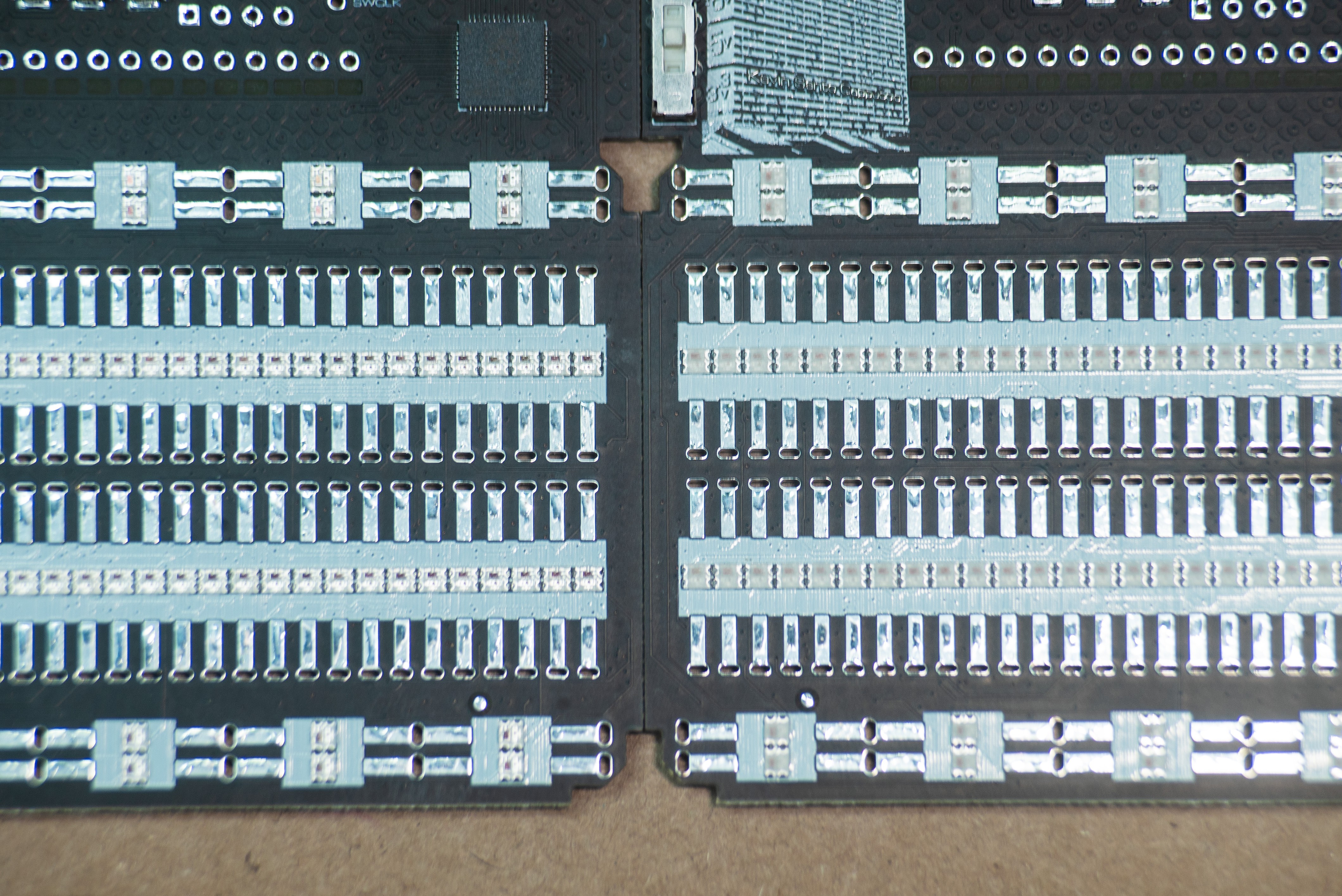
- Main board (all the SMD stuff assembled)
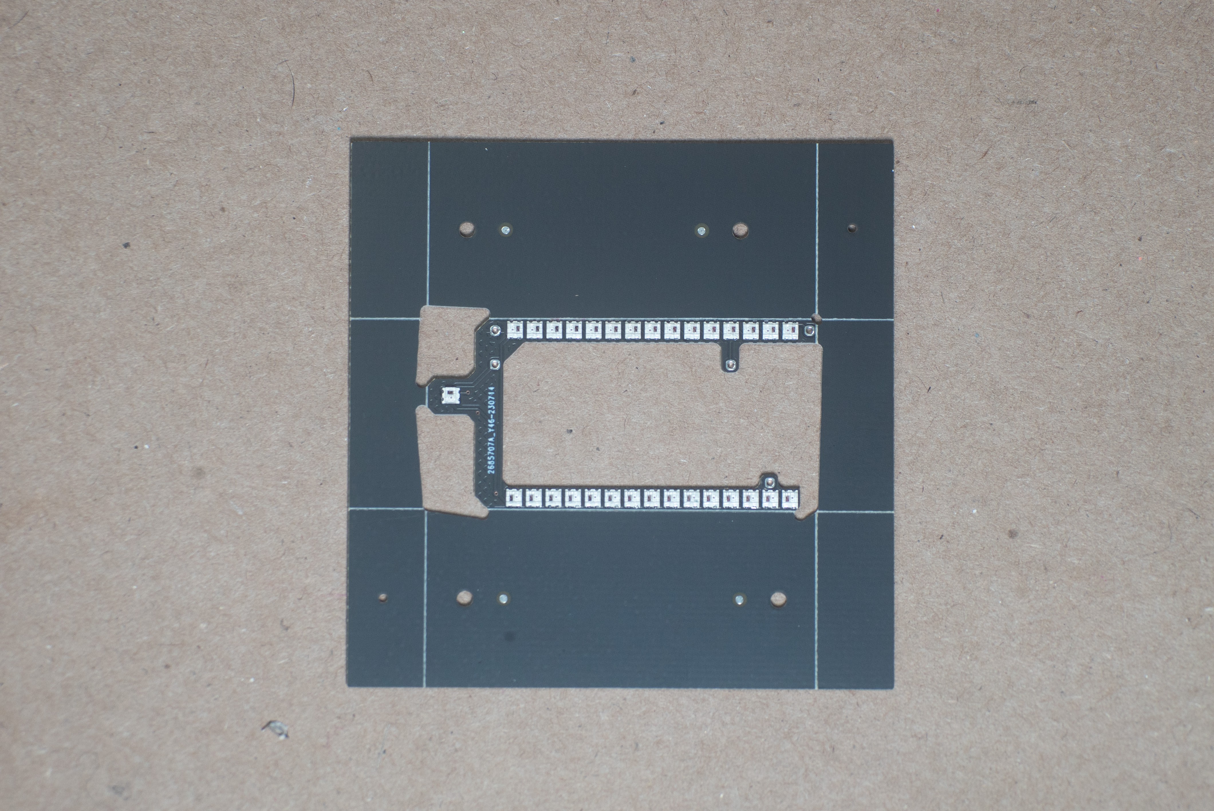
- LED “wishbone” board (the LEDs around the header that shine through the board)
- 2 x 15 pin female headers
- Plastic breadboard shell
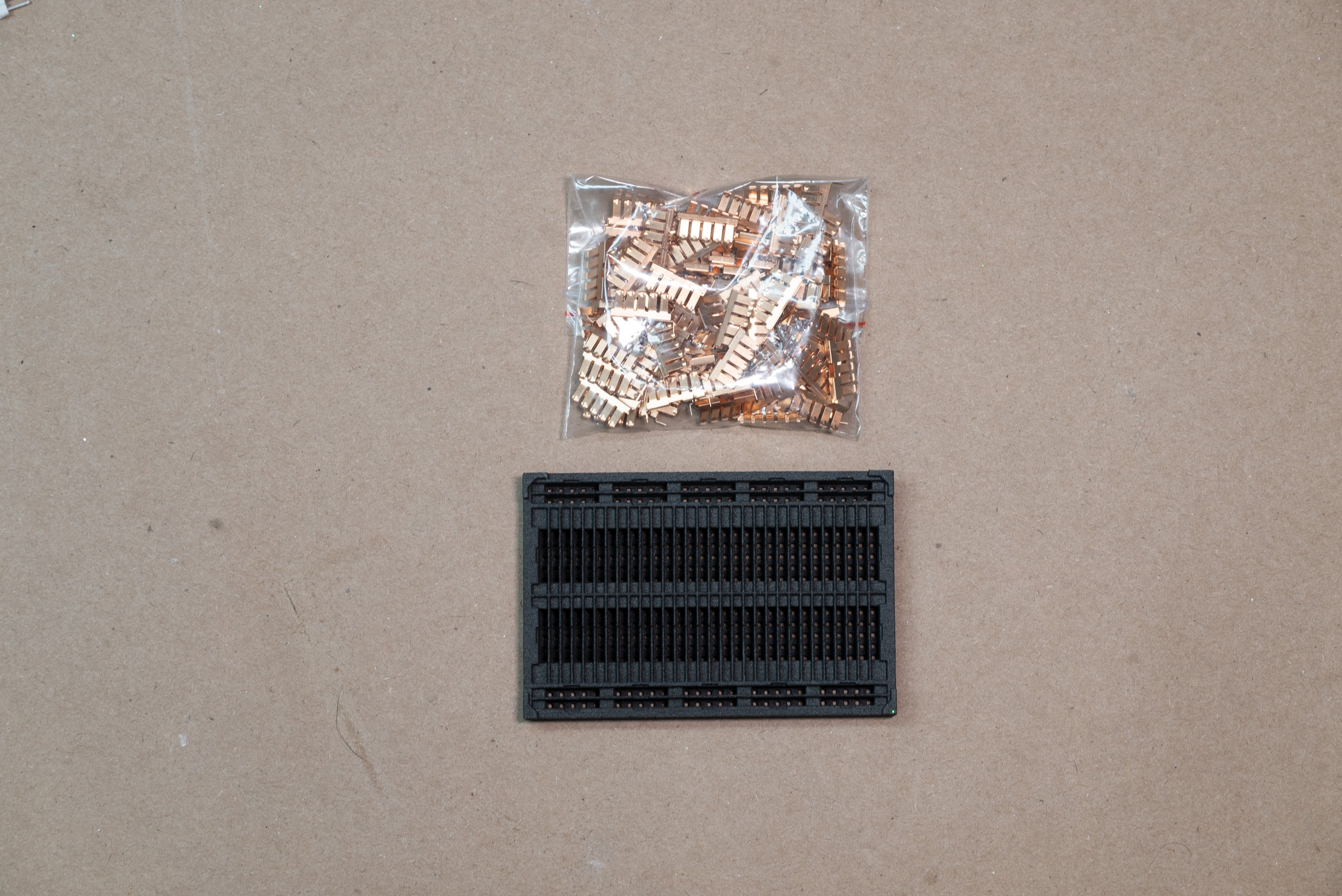
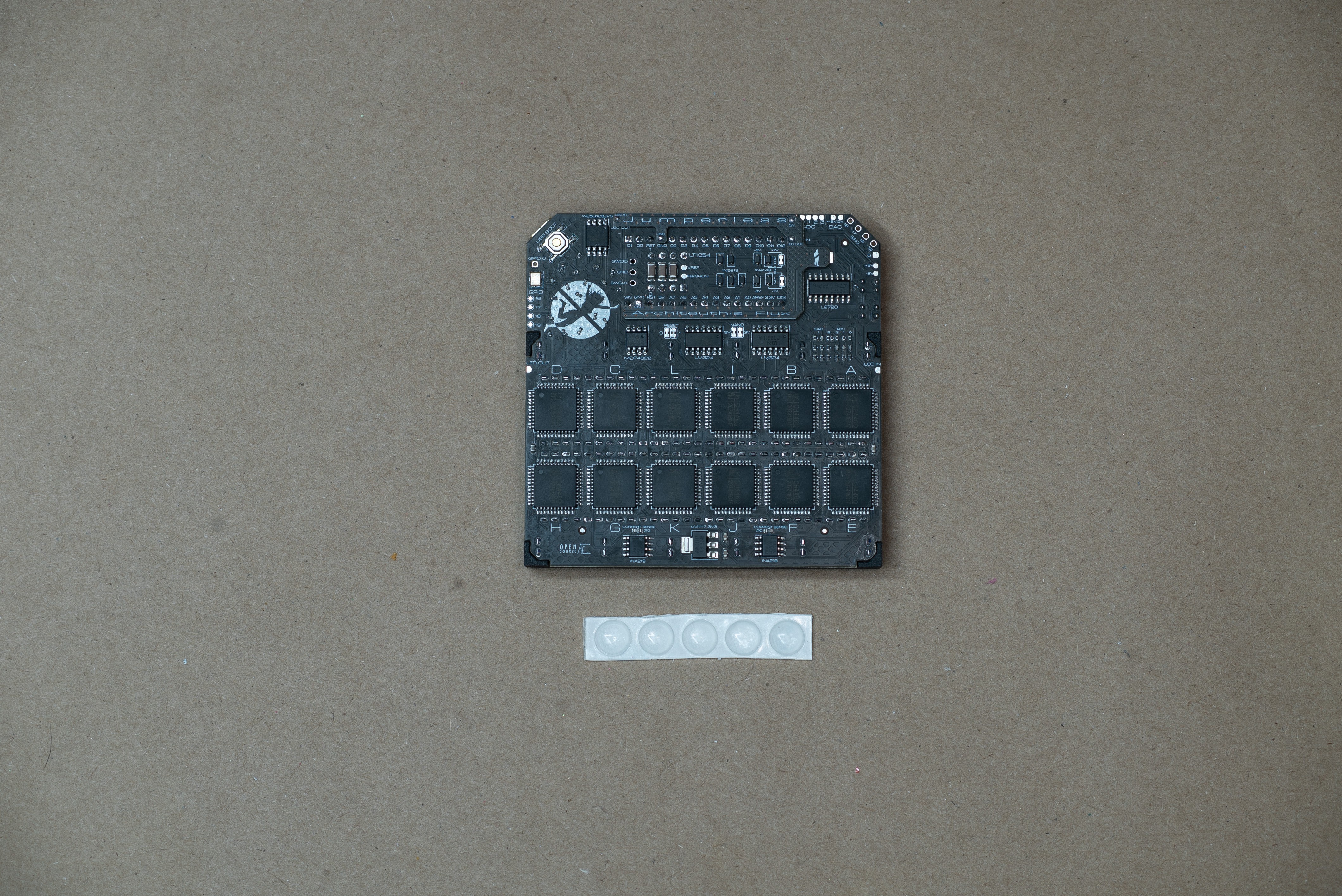
- 80 x breadboard spring clips
- 1 x LT1054 in 8 pin DIP
- 4 x Sticky-backed rubber feet
I also include some:
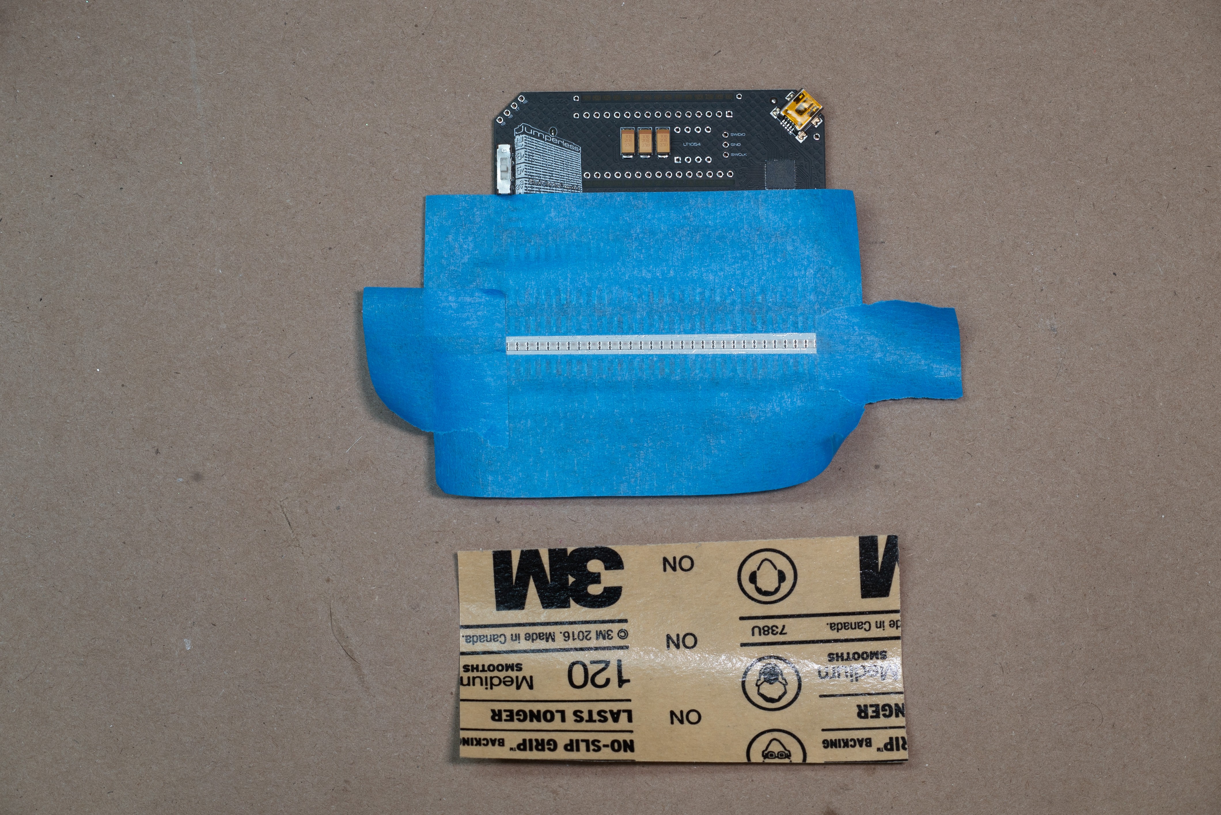
- sandpaper
-masking tape
- ~4 feet of solder.
The reason I'm including solder is that when you're just starting out with electronics you think soldering is hard. It isn't, you've just been using crappy solder and no one told you how big of a difference it makes. So I include ~4 feet of Kester Sn63Pb37 0.8mm Type 44 solder, also known as, "the good shit."
The only things you'll need to provide yourself won't be consumed in the process, you can have them back when you're done:
- A soldering iron
- an Arduino Nano (or something with the same footprint to keep the headers aligned while soldering)
- 80 pins worth of .1" male headers. You need these to stick in the breadboard while soldering to make sure all the clips stay perfectly straight, if you don't have enough, just stick anything (DIP chips, Arduino Nanos, whatever) into all the holes and that should work fine.
- some Isopropyl alcohol or flux remover spray (okay I guess this does get used up)
- Carefully snap of the edge rails from the LED wishbone board. Put the V-cut on the edge of a table and slowly bend it until it breaks off.
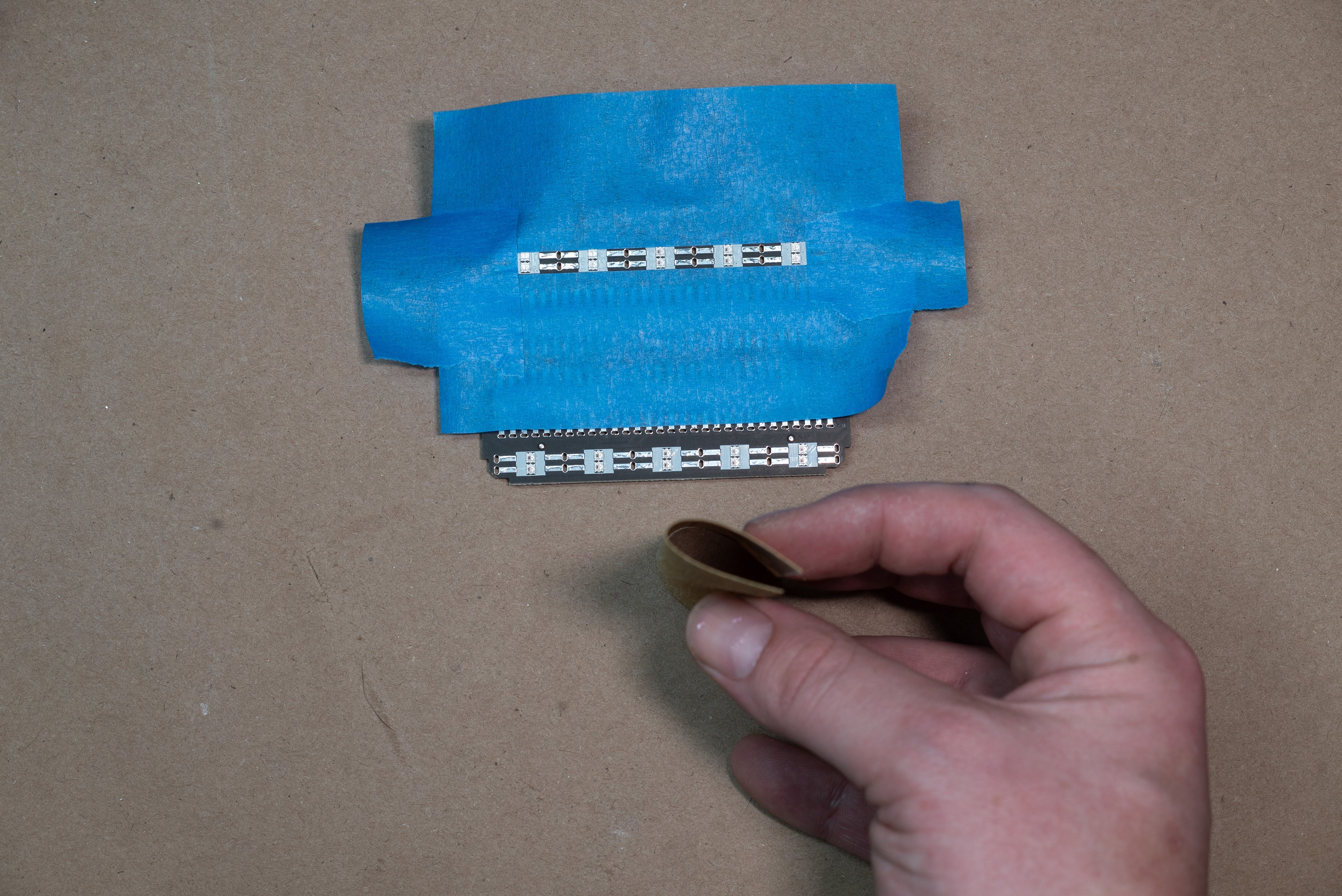
- Use the 300 grit sandpaper lightly on the tops of the LEDs on the main board to diffuse the light a bit, you don't need to do this on the reverse-mounted "wishbone" board. You can use masking tape so you don't accidentally sand the board for aesthetic reasons (but there are very few traces on the top layer and you shouldn't be sanding hard enough to break a trace.)
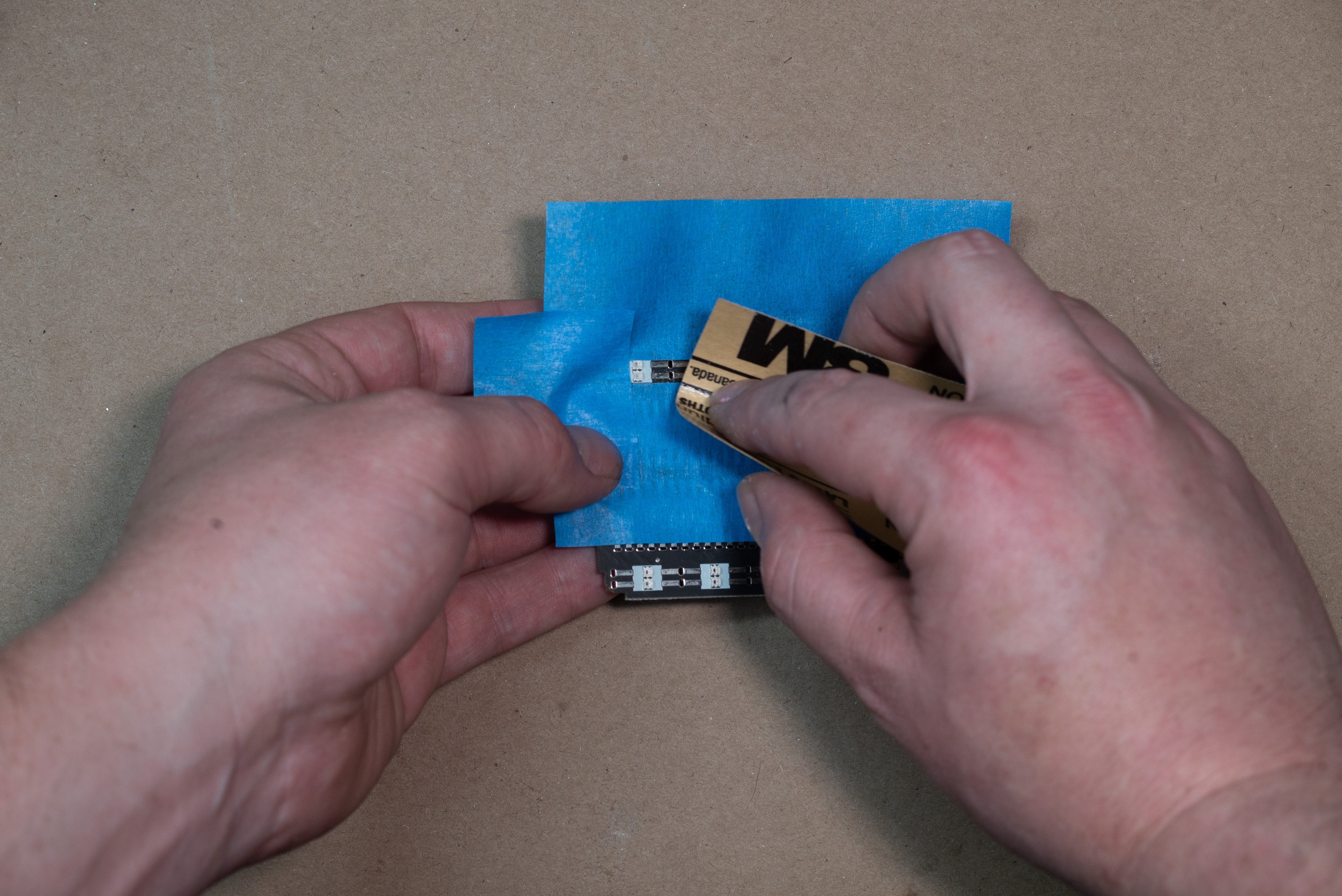
When you're finished the LEDs should look like this (before is on the left)
- Put the spring clips into the breadboard shell first and make sure they're all pushed all the way in. Then gently put that onto the main PCB, it may take some careful wiggling to coax all the tabs on the spring clips to go into their holes. If you can't get it seated, take it off and check that they're all straight and in a nice row. If some are giving you trouble, bend it back or swap it out (I have included extras.)
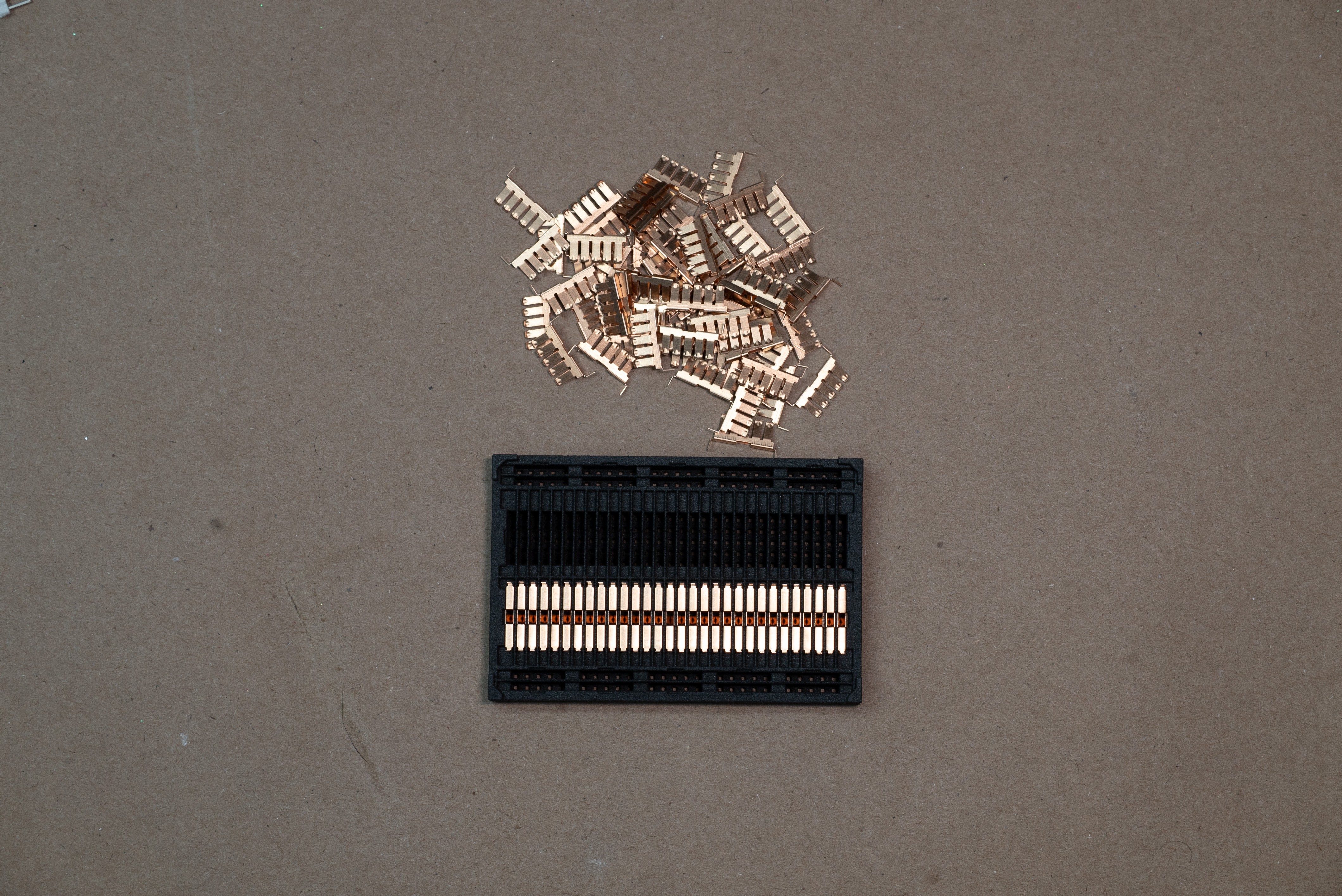
- Stick pin headers into every row of the breadboard and leave them in for soldering. Put them in one hole from the center hole. This makes sure that all the clips are perfectly aligned.
- Solder all the clips, it works best to use a large soldering iron tip and start from the middle on each row. The breadboard will expand slightly as it gets warm so I try to account for that by making sure it expands evenly from the center.
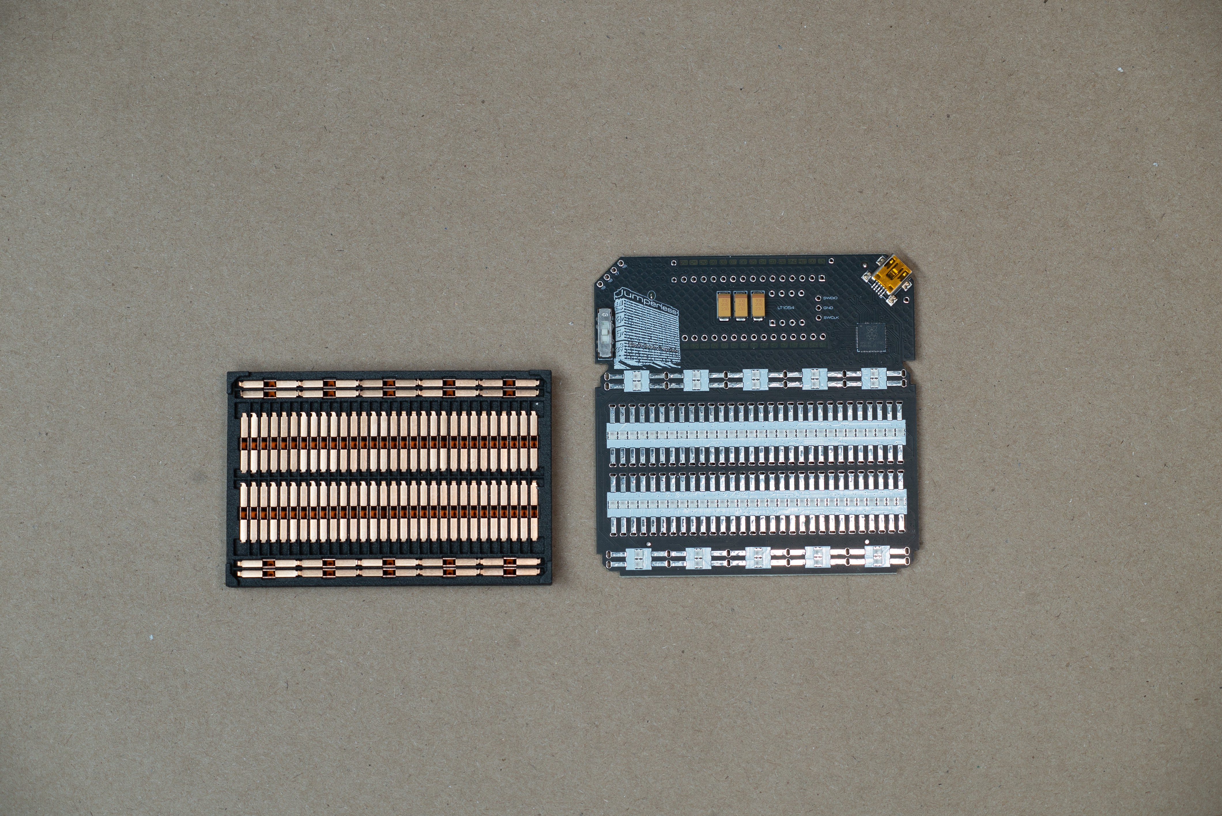
- Place the LT1054 into the footprint between the headers, on the front side of the board. Pin 1 is the bottom left (the square pad) so the notch on the chip should be towards the big yellow capacitors.
- Stick an Arduino Nano in the top headers while you solder them so they stay straight, before doing anything with the wishbone LED board. And wiggle it around to find the nicest looking position (the holes are slightly bigger than the pins so you can wiggle it ~0.5mm) if you're a total perfectionist like me. Then solder it in.
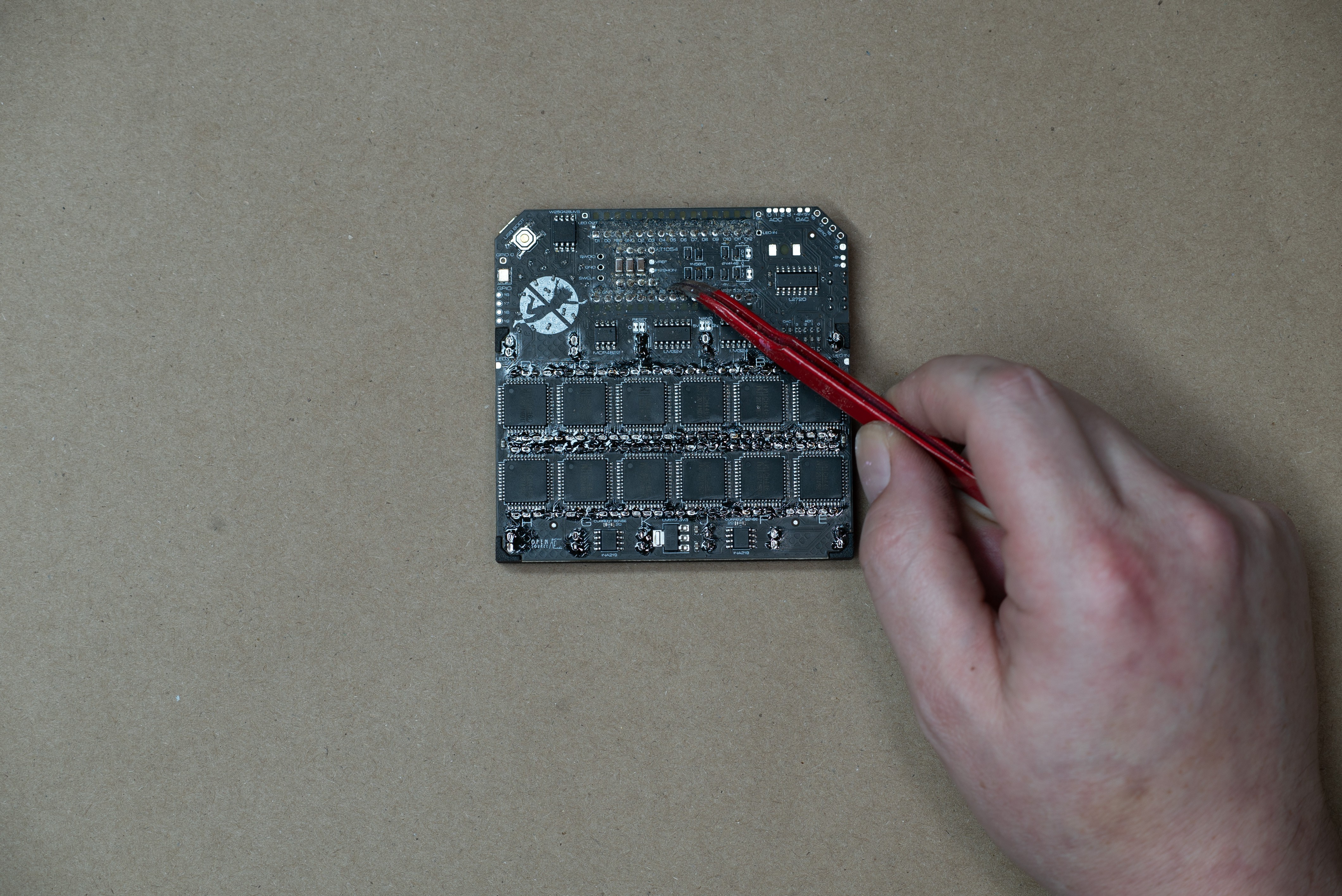
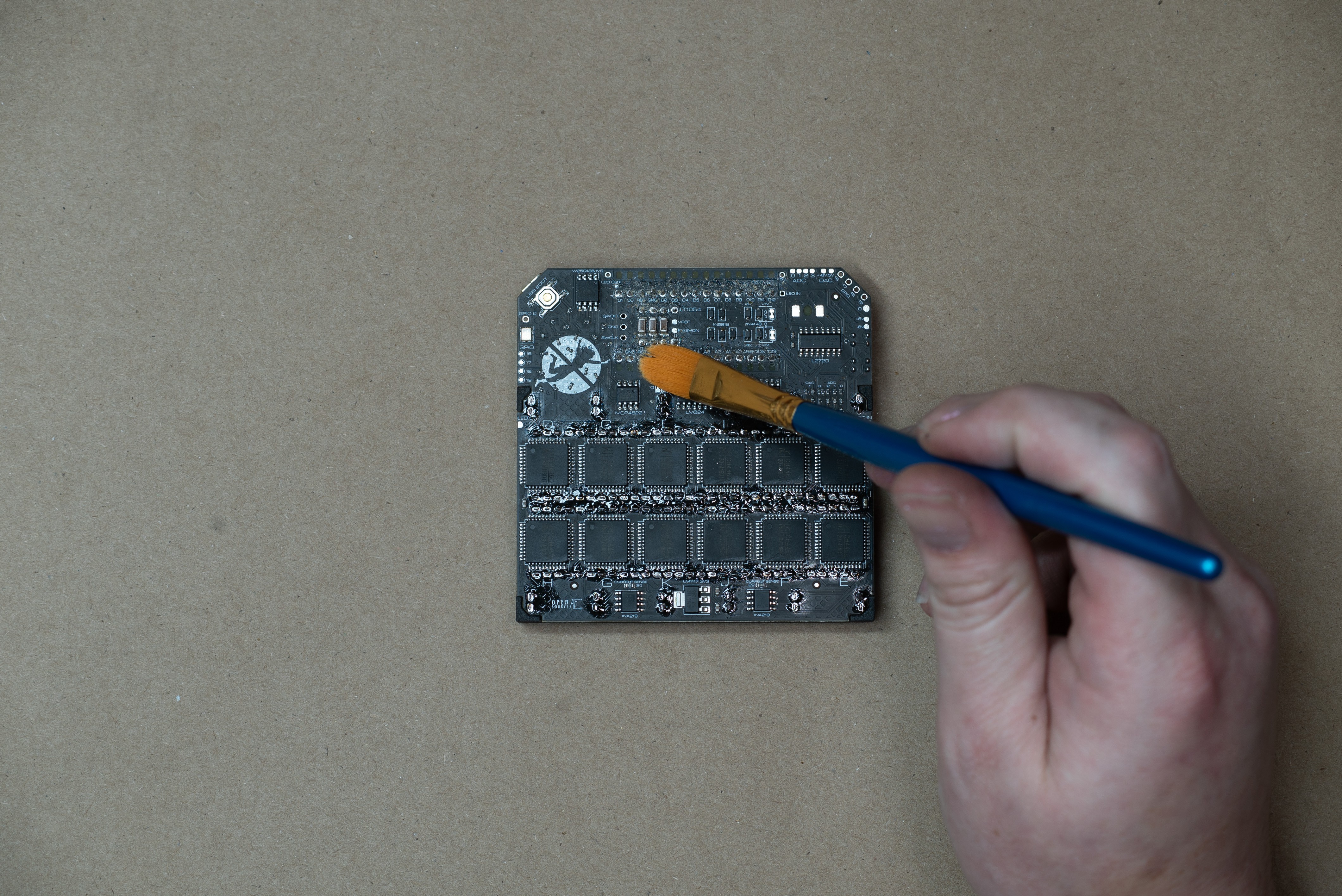
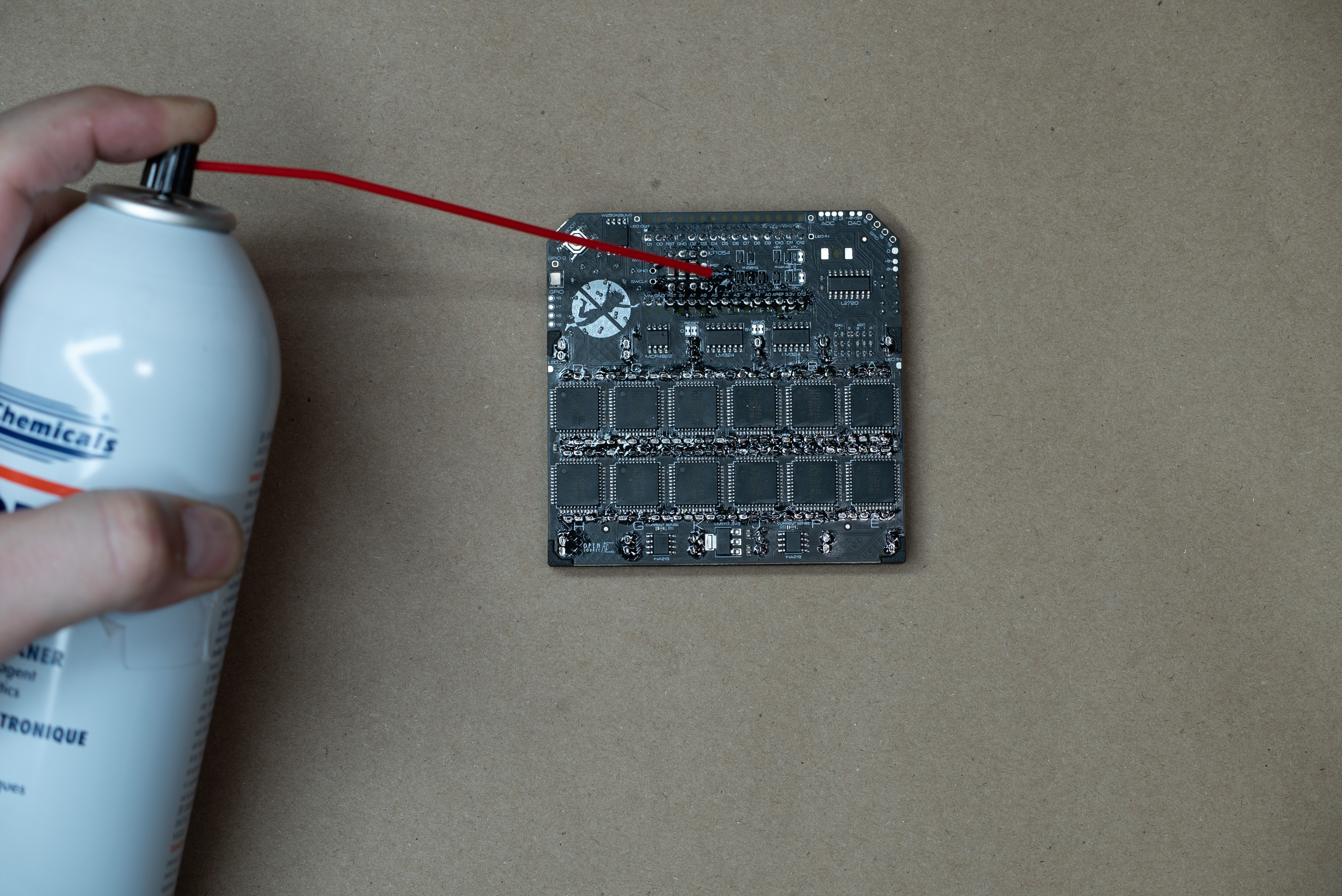
- You'll want to clean off the flux before you put on the wishbone board so there isn't any flux between the LEDs and the PCB. I like to shatter it all by dragging pokey tweezers over it, brush it off, and then use alcohol swabs or MG Chemicals Super Wash spray (this stuff is an absolute game changer, I recommend getting a can)
- For the wishbone board, solder the 2 inner ground pins directly to the backside of the female header pins that are sticking through. Make sure the LEDs lay flat to the main board.
- Stick the 3 other header pins through the wishbone board just far enough that they're flush on the top of the main board. If you stick the short side of the header pin up to the plastic, it turns out that is the perfect length. Tape the headers down so they don't fall out when you flip the board. Solder from the front of the main board first so it's just a flat spot of solder. Now cut the header pins flush before soldering. None of this is strictly necessary, but it leaves the board looking really nice instead of having soldered-then-cut poky headers.
- Clean off all the flux like you did above.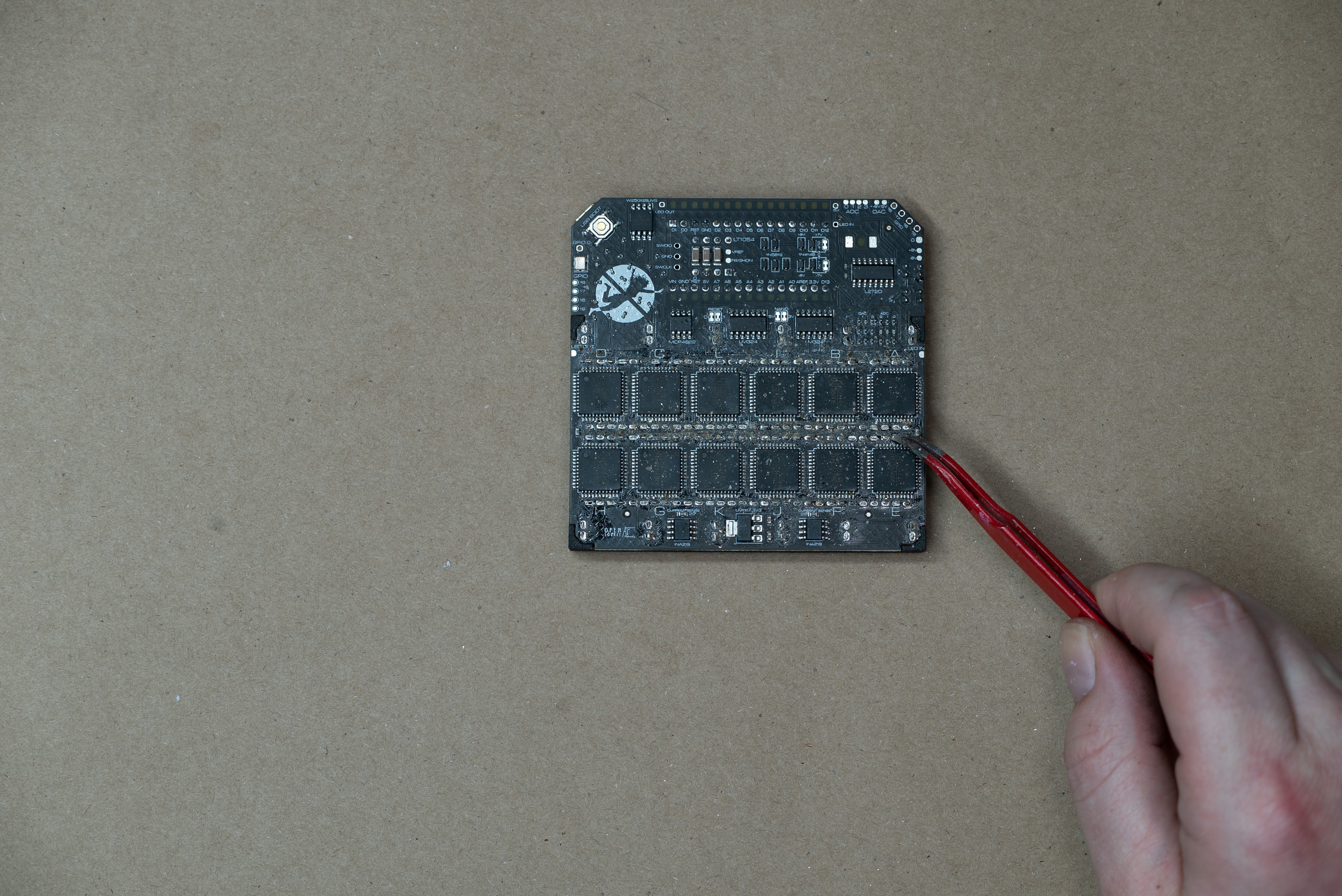
- Peel and stick the rubber feet, 2 on the bottom, 1 by the GPIO headers, and 1 just under the logo on the back. If it's a bit wobbly, a small amount of heat will soften the one giving you issues, then press it onto a flat surface until the wobbliness is gone.
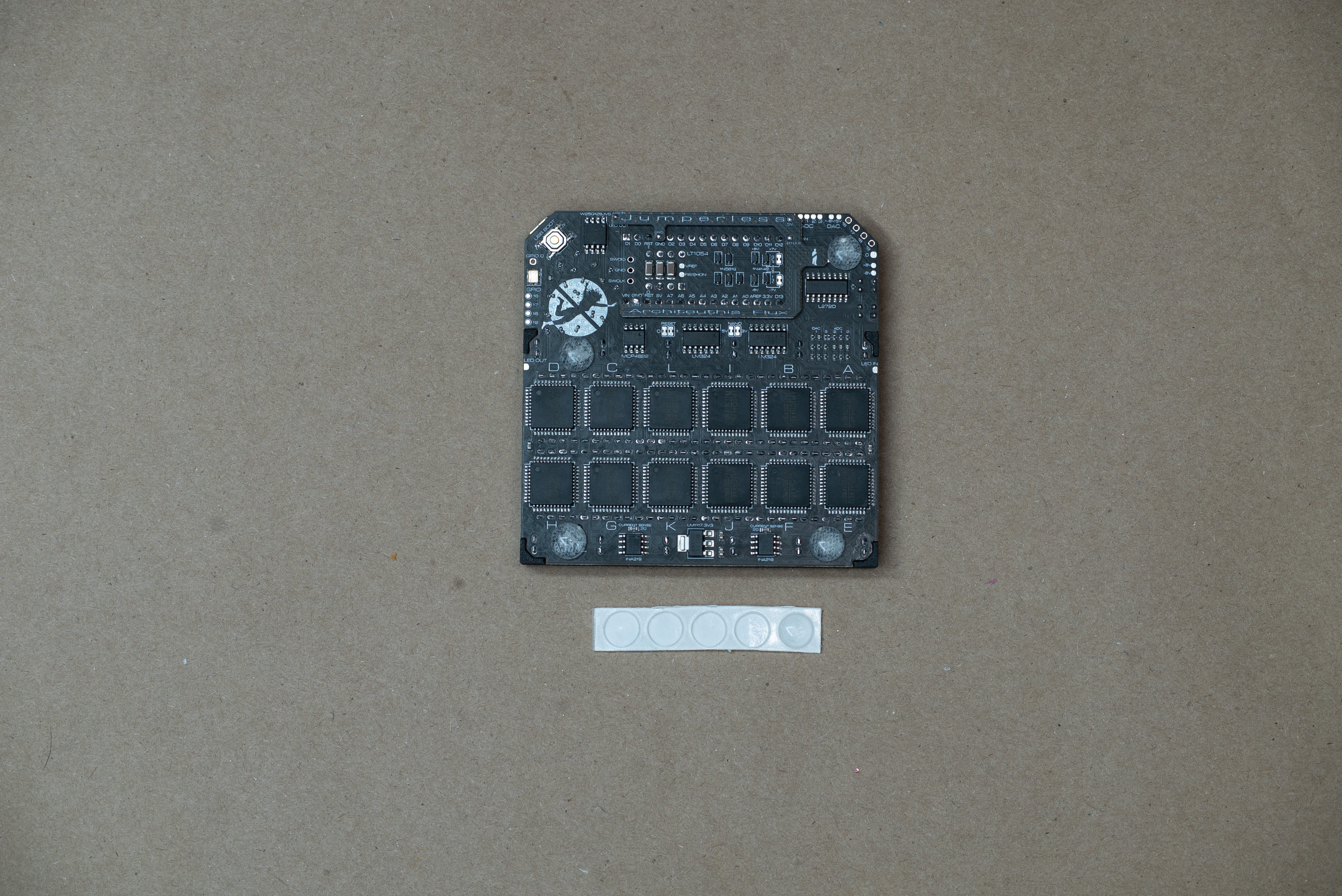
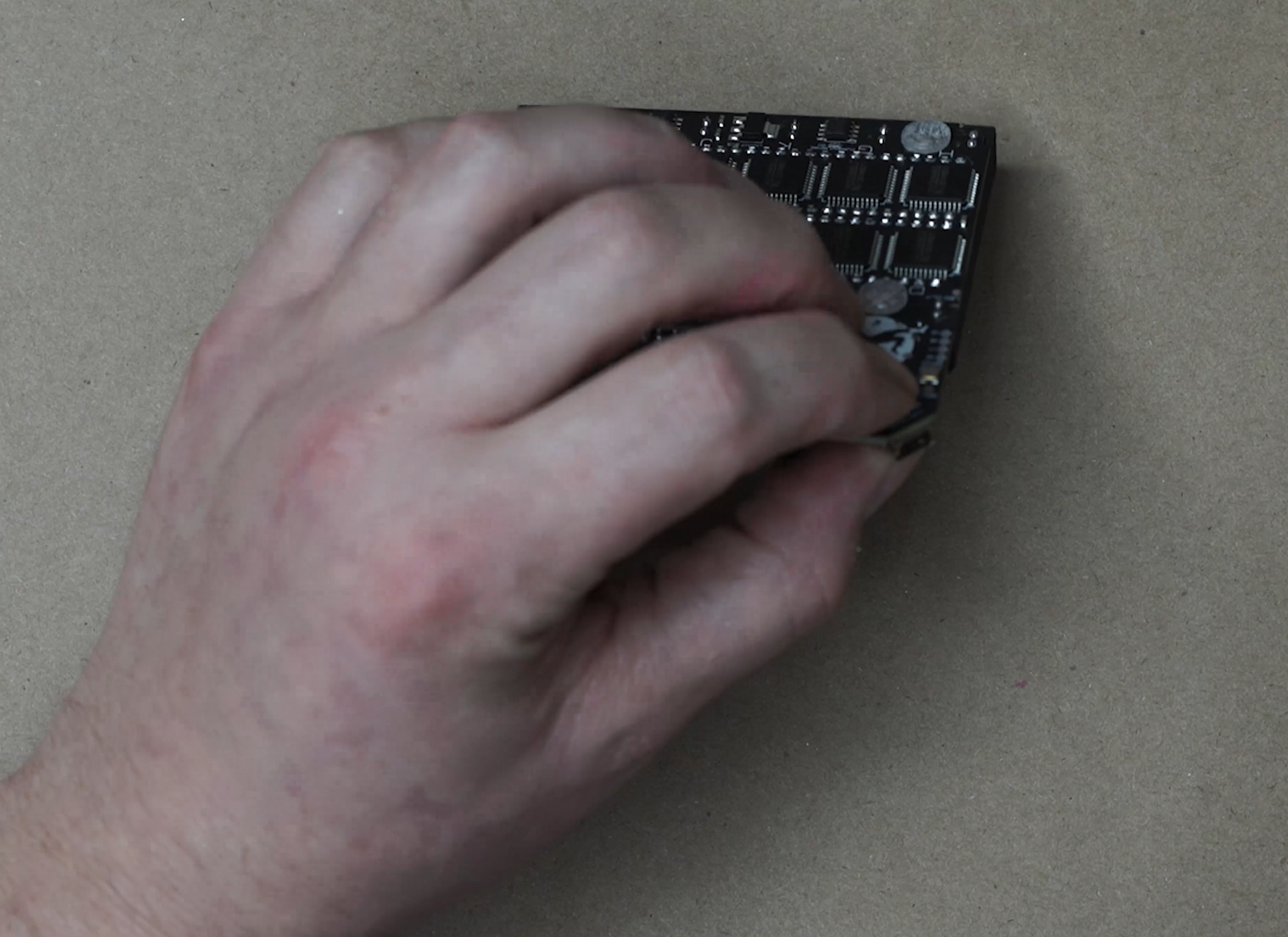
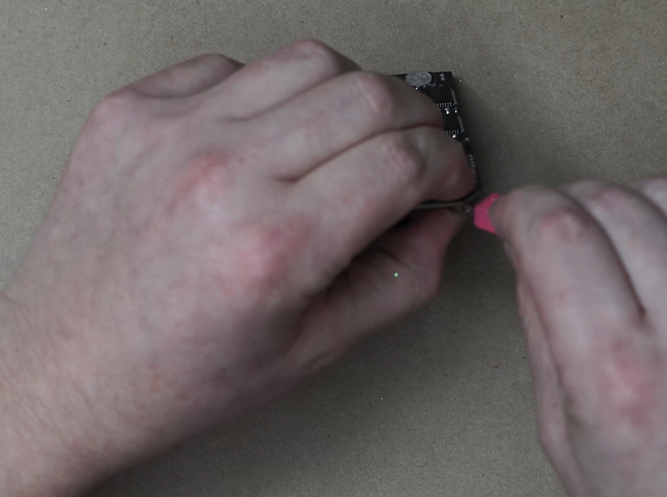
- You can load the firmware by plugging it in with the USB Boot button held and dragging the .uf2 file from here into the drive that pops up as RPI-RP2
And your Jumperless should be good to go!
Project Logs
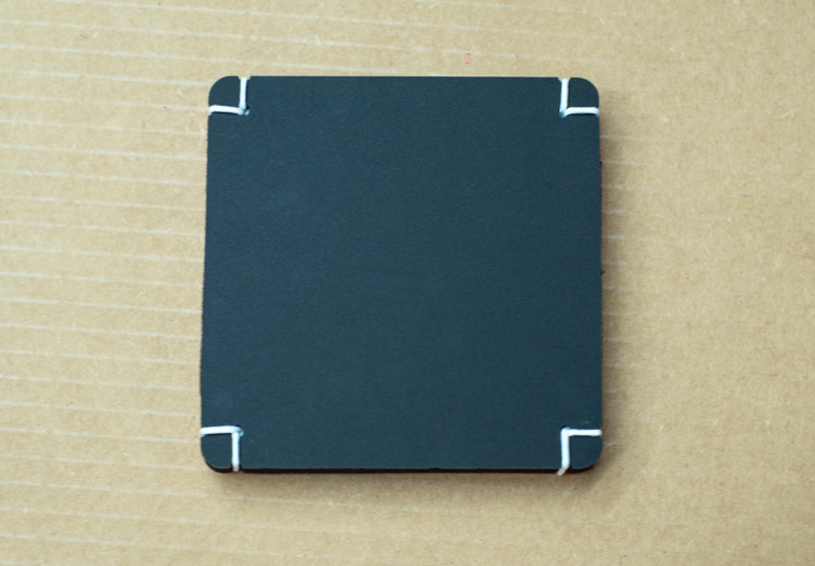
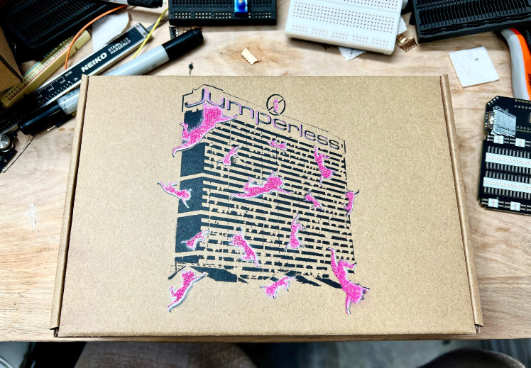
After all this about packaging, I decided the cardboard wouldn't really hold up well, so I went with acrylic and foam. Now they look like this
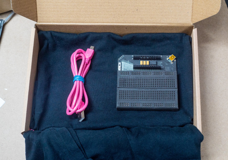
So this is me kind of procrastinating, but I've designed an inner case to keep the Jumperless nice and cozy inside it's box. I figured instead of using disposable packing materials, I'd have some shirts made and use them instead of bubble wrap.


But having the Jumperless just loose in that shirt looks kinda ghetto to me.
So I needed a smaller box to actually keep it safe wrapped up in that shirt that still leaves room for the other stuff. So this full foam cutout wasn't gonna cut it.
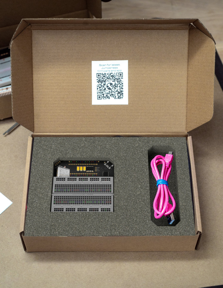
Originally it was just going to be 2 squares of cardboard with foam around it, but when I was ordering the cardboard and foam cutouts from Ponoko, I noticed they really only charge by the area of material, the actual cuts only seem to affect the cost by a few percent.
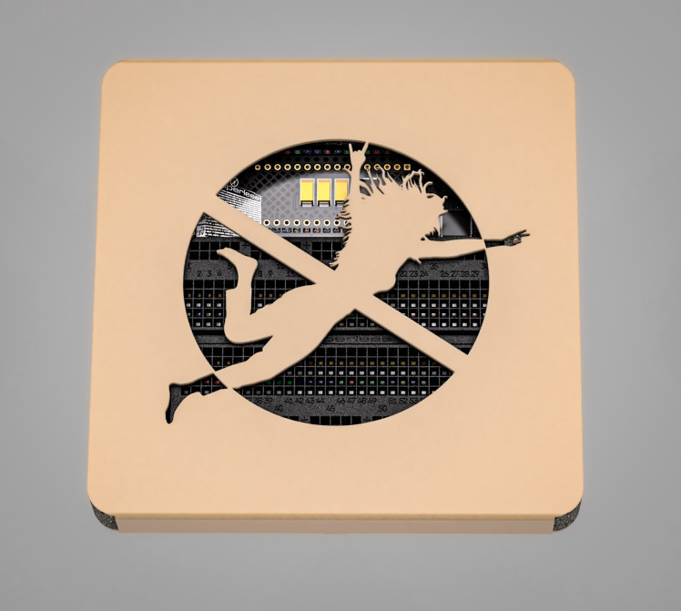
I also kinda felt like this logo wasn't getting enough love.

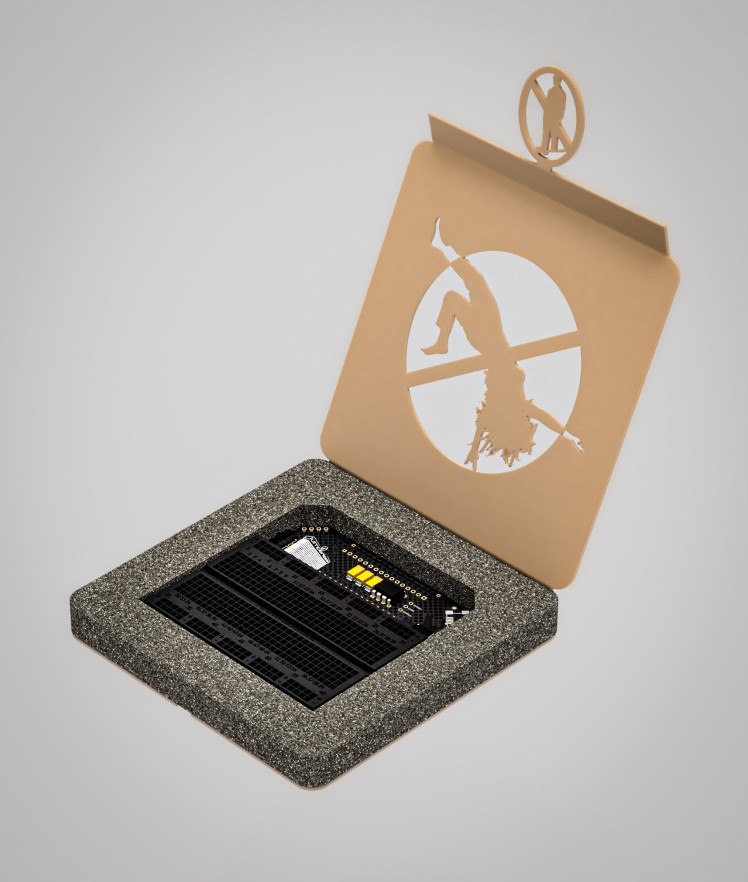
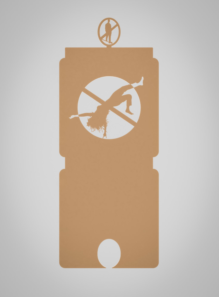
So I designed this box which should also serve as a storage case for people who like to keep their things in boxes.
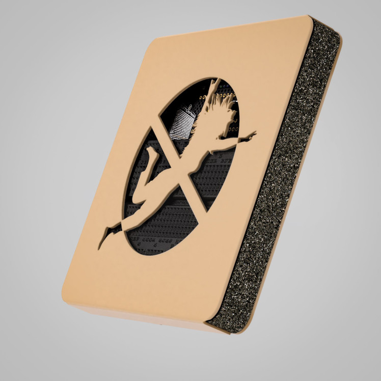
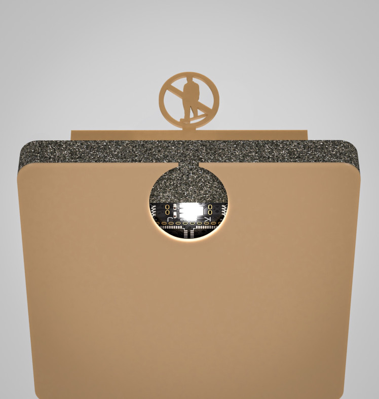
The cool thing is how it (hopefully) stays shut. This oval at the top should slot into the cutout at the bottom, and there should be enough friction and foldiness to keep it closed.

We'll see.
I should do a writeup on my failed attempts to use my 3018 cheapy CNC machine to hot wire cut foam. But now that Ponoko will cut foam for you, I decided to leave that to the pros.
Anyway, here's a simulated experience of opening a Jumperless now

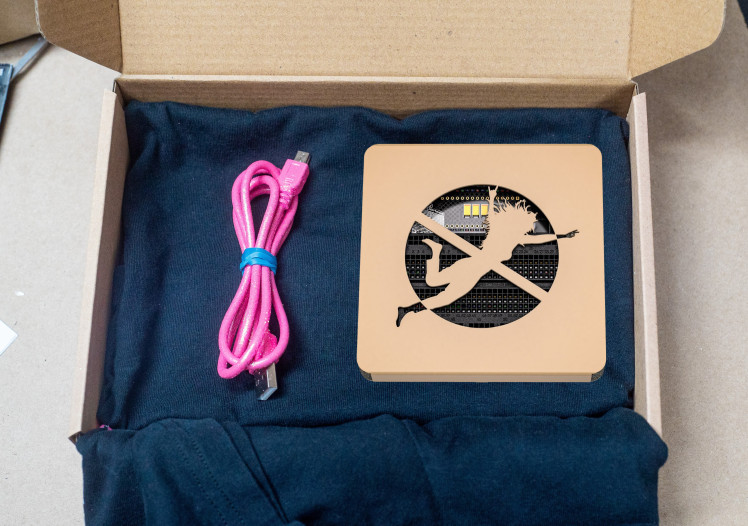

**Angelic noises**
Schematics, diagrams and documents
CAD, enclosures and custom parts
Code
Credits
Related products


Leave your feedback...