
Interfacing Hall Effect Sensor With Arduino

About the project
In this project, we have used a hall sensor that is able to detect a magnet and also the pole of the magnet.
Project info
Difficulty: Moderate
Platforms: Arduino
Estimated time: 2 days
License: GNU General Public License, version 3 or later (GPL3+)
Items used in this project
Hardware components


Story
About Project
HallEffect Sensor:
Few tips about Hall Sensor are as follows: The digital Hall sensor can only recognize if a magnet is present or not (0 or 1) but an analog hall sensor’s output varies depends on the magnetic field around the magnet that is it can recognize how powerful or how distant the magnet is. This project will direct only at the digital Hall sensors for they are the most usually utilized ones.
As per law “when a conductor or semiconductor with current flowing in one direction was organized perpendicular to a magnetic field a voltage could be estimated at right angles to the current path”.
With the help of this technique, the hall sensor will be capable to recognize the appearance of the magnet around it.
Hall Sensor Effect

Hall Sensor Effect
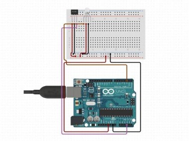
Arduino Hall Effect Sensor Working
Once we upload the code to the Arduino. We have utilized a 9V battery to power the whole set-up you can utilize any preferable power source. Now take the magnet close to the sensor and your LED will shine and if you get it away it will turn off.
What really happens inside is, when we take the magnet close to the sensor modifies its state. This change is sensed by the interrupt pin which will ask the toggle function inside which we change the variable “state” from 0 to 1. Hence the LED will turn on.
Now, when we drive the magnet away from the sensor, again the output of the sensor will develop. This change is again mentioned by our interrupt statement and hence the variable “state” will be modified from 1 to 0. Thus the LED if Turned off. The same repeats every time you take a magnet close to the sensor.
Code
Credits
Related products


Leave your feedback...