
Intelligent Home Burglar Alarm

Made by Al / Home Automation
About the project
BT Mesh is used to link all sensors together. Each sensor board has a switch input and PIR (Passive Infra Red) sensor. Optionally a microphone. More than one sensor has to give a trigger before the alarm goes off to reduce false alarms.
Project info
Difficulty: Easy
Platforms: Cypress
Estimated time: 1 hour
License: GNU General Public License, version 3 or later (GPL3+)
Items used in this project

Story
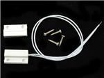
The master plan is to build a scalable, wireless, burglar alarm system. Each BT-Mesh board has a PIR sensor and a switch input that can be connected to a variety of sensors such as reed-relay + magnet door/window switches, under-carpet pressure pads and infra-red beams.
In the past, a typical home alarm would consist of a central control box wired up to all the sensors. This approach has several major disadvantages: 1. house wiring can be costly to do especially if the wiring is to be hidden and 2. these large wires can act as aerials and high RF fields may cause false alarms unless additional components such as opto-isolators and LC filters are added.
RF-linked alarms may well have a regular 'All's Well' message sent. To reduce the likelihood of spoofing 'meta-data', this system will send at random intervals. The BT-Mesh system encodes all messages with a network key and also an App key, and a message count incrementing means that replaying an old message will fail. This method of encrypting with a NWK_KEY, APP_KEY and message counter is also used by LoRaWAN.
I did a LoRaWAN project last year. You do not send a single bit unless necessary. Message frequency is limited and packet sizes have to be kept as small as possible. Range is maybe up to 20km, so there could be many thousands of these devices in the coverage area and so data collisions ultimately limit throughput. The data sheet was only a few pages long so it was much easier to get running than this MESH stuff where there are loads of data sheets and the high-level coding needs a lot more thought. A long time ago I built a transmitter with an 807 beam-tetrode ;-)
To reduce false triggering of an alarm, two sensors will have to detect an intruder within a few minutes.
The home owner can set and clear the alarm from a mobile phone. This could be done by BT-link if within range otherwise by text messages or via Wi-Fi etc. As my phone is about to lose support soon, it runs under Win10, I will not do this section.
One of the BT-mesh boards will be functionally connected in parallel with the front door bell switch. A BT message can alert the user's phone if within range, and that range could be 'up to' 700 feet so will cover both house and garden of many properties. Door bell and intruder alert messages can make the phone ring with different sounds.
Therefore messages we need are REED_RELAY states, PIR states and DOOR_BELL state. Each message should send a location. Each MESH board can have both reed-relay input and PIR. An output MESH board will have some kind of audible warning device and a reset button which could be key-operated. The PIR devices use hardly any power. I could not find any figures on them except for the term 'ultra low power'. They could well be temperature-sensitive. Suffice to say, PIR sensors could probably run on a BT-Mesh board for a long time on a coin cell which makes them convenient as burglar alarm sensors.
Work in Progress:
First problem was getting the demos to work with the BT_SDK-1.2. The solution was to get BT_SDK-1.4.
Once that was done, it was possible to run the on-off-switch demo on one board and light_dimmer on another. The boards could be provisioned by running a Mesh Client app on a laptop. Mesh Client fails on this full-size PC with the error message 'Bluetooth radio is not present or not functioning. Please plug in the dongle and try again.' That is a lot more informative than most of the errors I see on this PC which usually state 'Unknown Error!'.
To start with something easy, it would be great if all switch messages sent by the mesh boards caused a green LED to glow on the final board ( alarm ), and PIR detection cause its red LED to glow. Another mod to make things easy is to use the USER switch to simulate the reed-relay switch. Normally the reed-relay is closed, so we will have to invert the logic when it is eventually connected.
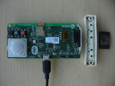
The CYBT-213043MESH board has a 35-pad module fitted: a CYBT-213043. Inside the module is a Cypress BT 5.0 SoC, a CYW20819. The latter SoC comes in two BGA packs. The larger 112-pin has microphone inputs which may be handy for its stereo PDM mic input, as mentioned in the data sheet. The SoC has a 20x8 keypad scanner which could be used for a code-entry disarm function, although the MESH kit does not bring these pins out to the two SIL connectors.
As to pins, I have traced the RGB LED pins on the schematic and they are named P6, P3 and P4 respectively. A low on the pin will energise the LED. These pins are defined in wiced_platform.h as follows:
#define LED_RED WICED_P06
#define LED_BLUE WICED_P04
#define LED_GREEN WICED_P03
#define WICED_GPIO_PIN_LED_1 LED_BLUE
#define WICED_GPIO_PIN_LED_2 LED_RED
#define WICED_GPIO_PIN_LED_3 LED_GREEN
My tiny brain-cell gets confused by all these multiple definitions!
So in led_control.c we see some references to
wiced_bt_gpio_numbers_t led_pin = WICED_GPIO_PIN_LED_2;
and setup for the PWM to change the brightness of the LEDs. As we don't really need PWM to control the LED brightness, we can use two PWM channels to produce audio tones and amplitude envelope so we can mimic a bell sound. In fact we could use any spare PWM channels to generate the weird harmonic structure of a bell, but for the time being a square wave of something like 800Hz and 1kHz could be used for the bell sound with amplitude dropping over 5 seconds. The amplitude channel would be PWM of 20kHz such that the mark-space ratio varies from 0 to 100%. Its output can be RC filtered to produce a DC voltage for the audio transducer.
I used my phone to record the sound and will feed that into Audacity when I get a spare minute; Audacity's spectral analysis will show the two bell fundamental tones.
There are plenty of questions I have about how to deal with multiple messages from the different boards, so the obvious step is to program the boards with switchsmart and light_smart demos and press buttons while monitoring USB messages...
Well that did not go very well because the Modus Toolbox IDE could not find a serial port even though Windows came up with sensible messages about getting a new USB device ready. A visit to Device Manage showed not only the Dual-Channel USB port but also an Unknown device. I let Windows find a suitable driver for the latter device online, and once the unknown device had gone away, Modus happily detected the Mesh boards and downloaded the relevant FW. Great! But now the laptop is unable to run Mesh Client and it cannot find the drivers for the Dual-Channel USB device. I suspect that Windows has done some kind of update and the laptop needs the latest version. So work has ground to a halt while that happens.
On a brighter note, I ran up two copies of RealTerm at 921600Bd and can see button press change messages which is exciting. Also the LightSmart board's red LED responds to presses of its User button. The boards have not yet been provisioned, so they don't communicate.
Well, last day now! I let the laptop update Windows overnight. It was able to detect the two boards I programmed yesterday via BT, but sadly there was no change in their behaviour and zero communications between them. Mesh Client could not get or set anything, all I get is a 'not in DB' error message. Funny that, because last weekend I had the two boards talking nicely.
Another problem is that every time I reprogram a board, it comes up with a new name, so my network is full of old node names that are no longer in use and I can see no obvious way to delete them.
Mesh Client seems to have the ability to set up multiple networks and multiple groups. That could be useful.
Also useful is the WICED Studio™ v5.0.1 - API Reference Guide. It has some timers that would be good for my auto-decrement of the PIR/reed switch events. MshMDLv1.0.1.pdf has plenty of information about driving LEDs via BT-Mesh.
Unfortunately I need to discover what has gone horribly wrong with the board BT comms. I had better re-read the relevant readme.txt files and maybe set up a new network in Mesh Client. If that fails, return to the simple on-off-switch and dimmer examples as they worked last Saturday. Interesting! The boards work as before until the User switch is pressed then the red LED stays off until the board is re-provisioned.
Well, finally run out of time! I have put in a dummy User button int handler in light_dimmable so presses do not cause trouble any more. I have also modified the on-off-switch code to send an onoff status of 1 when the door bell is activated. This causes the green LED to glow on the Alarm board and stay on. To clear the LED, hold the doorbell switch for between 5 and 15 seconds. What is needed is a return BT path to clear the onoff status to zero. PIR not working yet due to running out of time.
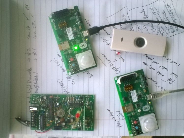
That's all folks! Below is photo of 2 mesh boards, doorbell button and old-school wireless PIR sensor.
Schematics, diagrams and documents
Code
Credits
Al
Been a keen radio amateur for many years. HF CW activity when I get the chance...homebrew radios and gadgets from valve amplifiers using EL84s etc in the past to a TV sound-bar using an Arduino and Class-D amplifier. I have been trying to build an electronic organ for a while but technology changes before I get anywhere!

Leave your feedback...