
Integration Of Surilli Basic M0 With Mq135 And 16x2 Lcd

Made by surilli-io / IoT
About the project
Air quality monitoring with MQ135 sensor and Surilli Basic M0 and then observing the values on your LCD.
Project info
Difficulty: Easy
Platforms: Arduino
Estimated time: 1 hour
License: GNU General Public License, version 3 or later (GPL3+)
Items used in this project
Hardware components

Story
About:
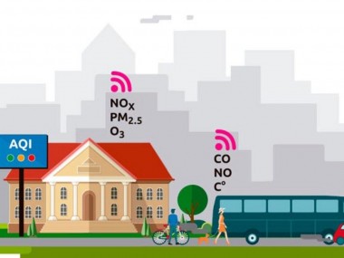
In today’s world, we encounter different scenario where we see different gasses being emitted in atmosphere such as home appliances like air conditioner and industrial chimneys. Monitoring of these gasses is very important with safety point of view. Gas Sensors are very helpful in accomplishing this task. Small nose like sensor spontaneously respond to the alteration of gas concentration and keep our systems updated for special tasks.
In this tutorial, we will integrate MQ135 sensor with Surilli Basic M0. The value of the Air Quality will be monitored on the 16x2 LCD Screen.
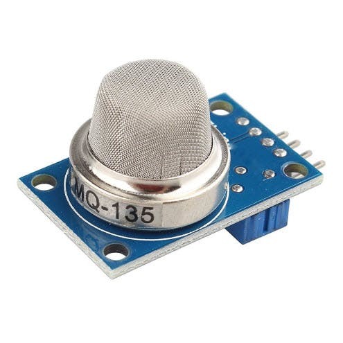
MQ135 Sensor:
The MQ135 Sensor Module consists of a steel exoskeleton under which a sensing element is housed. This sensing element is subjected to current through connecting leads. This current is known as heating current through it, the gases coming close to the sensing element get ionized and are absorbed by the sensing element. This changes the resistance of the sensing element which alters the value of the current going out of it.
The MQ-135 gas sensor senses the gases like ammonia nitrogen, oxygen, alcohols, aromatic compounds, sulfide and smoke. The operating voltage of this gas sensor is from 2.5V to 5.0V. MQ-135 gas sensor can be implementation to detect the smoke, benzene, steam and other harmful gases.
Working Principle:
The MQ-135 alcohol sensor consists of a tin dioxide (SnO2), a perspective layer inside Aluminium Oxide micro tubes (measuring electrodes) and a heating element inside a tubular casing. The end face of the sensor is enclosed by a stainless steel net and the back side holds the connection terminals. Ethyl alcohol present in the breath is oxidized into acetic acid passing through the heat element. With the ethyl alcohol cascade on the tin dioxide sensing layer, the resistance decreases. By using the external load resistance the resistance variation is converted into a suitable voltage variation.
It has lower conductivity compare to clean air and due to air pollution the conductivity is increases. The air quality sensor detects ammonia, nitrogen oxide, smoke, CO2 and other harmful gases. The air quality sensor has a small potentiometer that permits the adjustment of the load resistance of the sensor circuit.
The air quality sensor is a signal output indicator instruction. It has two outputs: analog output and TTL output. The TTL output is low signal light which can be accessed through the IO ports on the microcontroller. The analog output is an concentration, i.e. increasing voltage is directly proportional to increasing concentration. The resistance of the sensor decreases as the concentration of the target gas is increased in PPM while for clean air its resistance remains constant.
The analog output voltage from the sensor can be assumed directly proportional to the concentration of CO2 gas in PPM under standard conditions. The analog voltage is sensed from the sensor and converted to a digital value in range from 0 to 1023 by the inbuilt ADC channel of the controller. The digitized value is hence equal to the gas concentration in PPM.
When no gas digital output is 1 and analog output gives 1023 max value. When gas is present digital output is 0 and analogue output is much less than 1023. Using potentiometer on chip we can control the turning OFF point of digital pin at some value of analog pin. The sensor needs a load-resistor at the output to ground. Its value could be from 2k Ohm to 47k Ohm.
The lower the value, the less sensitive is the sensor. The higher the value, the less accurate is sensor for higher concentrations of gas. If only one specific gas is measured, the load-resistor can be calibrated by applying a known concentration of that gas. If the sensor is used to measure any gas (like in a air quality detector) the load-resistor could be set for a value of about 1V output with clean air. Choosing a good value for the load-resistor is only valid after the burn-in time.
NOTE: Don’t touch the sensor, it will be very hot.
Features:
1. High sensitivity to Sulfide, benzene Department of steam, smoke and other harmful gases.2. Long life and low cost.3. Simple drive circuit.
Pin Configuration:
From left to right first pins are as follows:
A0 Analog output
D0 Digital output
GND Ground
Vcc Supply (5V)
Specifications of MQ-135 Gas Sensor:
- Wide detecting scope.
- Fast response and High sensitivity.
- Stable and long life Simple drive circuit.
- Used in air quality control equipment for buildings/offices, is suitable for detecting of NH3, NOx, alcohol, Benzene, smoke, CO2, etc.
- Size: 35mm x 22mm x 23mm (length x width x height).
- Working voltage: DC 5 V.
- Signal output instruction.
- Dual signal output (analog output, and high/low digital output).
- 0 ~ 4.2V analog output voltage, the higher the concentration the higher the voltage.
What Is PPM?
Parts per million (PPM) is a unit of measurement used for expressing a very dilute concentration level of pollutants in the air, water and other fluids or one item in a million of anything of the same size. PPM is a volume-to-volume ratio.
Changes in temperature and pressure do not change the ratio of the volume of pollutant gas to the volume of air that contains it.
16x2 LCD:
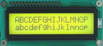
A 16x2 LCD has 2 horizontal rows each comprising of 16 displaying character. This means that a total of 32 characters can be displayed on a 16x2 LCD. An LCD is used in many electronics projects to display the status of the process, voltage levels, sensor values, system health and the list goes on n on.
PIN NUMBERING:
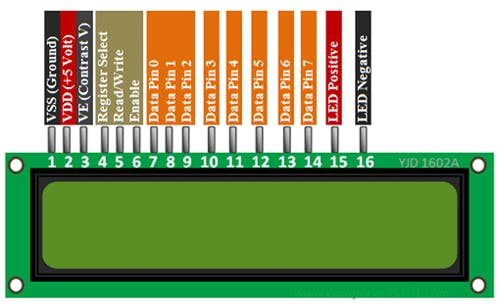
The PIN numbering goes from left to right (1 - 16).
Required Hardware:
1. Surilli Basic M0.
2. 16x2 LCD.
3. MQ135 Gas Sensor Module.
4. Connecting Wires.
5. Arduino IDE Software.
Connections:
MQ135 Sensor Module with Surilli Basic M0:
- -> PIN A0 (MQ135) to PIN A0 (Surilli Basic M0).
- -> GND PIN (MQ135) to GND PIN (Surilli Basic M0).
- -> VCC PIN (MQ135) to USB PIN (5V) (Surilli Basic M0).
16x2 LCD with Surilli Basic M0:
- -> VSS PIN (LCD) to GND PIN (Surilli Basic M0).
- -> VDD PIN (LCD) to 5V PIN (Surilli Basic M0).
- -> V0 PIN (LCD) to GND PIN (Surilli Basic M0).
- -> RS PIN (LCD) to A1 PIN (Surilli Basic M0).
- -> RW PIN (LCD) to GND PIN (Surilli Basic M0).
- -> E PIN (LCD) to A2 PIN (Surilli Basic M0).
- -> D4 PIN (LCD) to PIN 9 (Surilli Basic M0).
- -> D5 PIN (LCD) to PIN 10 (Surilli Basic M0).
- -> D6 PIN (LCD) to PIN 11 (Surilli Basic M0).
- -> D7 PIN (LCD) to PIN 6 (Surilli Basic M0).
- -> A PIN (LCD) to 5V PIN (Surilli Basic M0).
- -> K PIN (LCD) to GND PIN (Surilli Basic M0).
STEP 1: Set Up Arduino IDE for Surilli
Make sure you have selected the right port, board and processor for the Surilli as shown in the picture below and it is programmable (compile and upload “Blink” from File>Examples>Digital>Blink onto your Surilli to check if every thing is working fine).
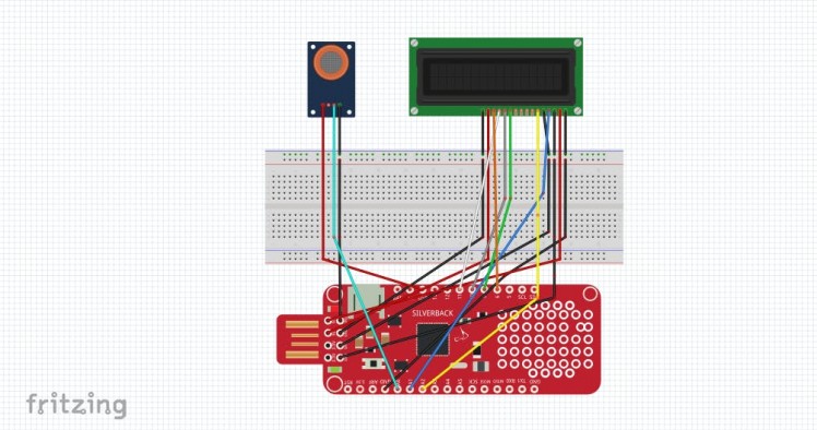
STEP 2: The Circuitry
The circuitry is a little complex so we will go through it first. Complete your circuit connections and then move on to the next step. It's mostly the programming. Follow the figure below to set up your hardware.
STEP 3: Upload & Burn Code Onto Surilli
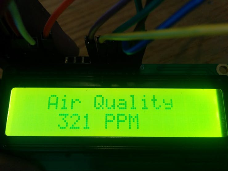
- Now you have completed setting up your hardware and Arduino IDE. Copy and paste the Arduino sketch given below into your Arduino IDE and hit upload.
- After the Arduino Code has been uploaded, the value for the Air Quality can be viewed on the 16x2 LCD Screen.
Code:
#include <LiquidCrystal.h>
int sensorValue;
const int rs = A1, en = A2, d4 = 9, d5 = 10, d6 = 11, d7 = 6;
LiquidCrystal lcd(rs, en, d4, d5, d6, d7);
void setup()
{
  lcd.begin(16, 2);
  SerialUSB.begin(9600);                            // Set the serial port to 9600
}
void loop()
{
 sensorValue = analogRead(0);                      // Read analog input pin A0
 SerialUSB.print("AirQua=");
 SerialUSB.print(sensorValue, DEC);                // Prints the value read
 SerialUSB.println(" PPM");
 lcd.setCursor(0,0);
 lcd.print("  Air Quality ");
 lcd.setCursor(0,1);
 lcd.print("   ");
 lcd.print(sensorValue,DEC);
 lcd.print(" PPM");
 lcd.print("   ");
 delay(1000);                                      // Wait 1000ms for next reading
}
Results:
The results obtained in our case is as follows:
Note: You can define the thresholds yourself keeping in mind the climatic changes and also referring to the concerned MET Department for the Air Quality of your area.
If you make something fun and interesting, do share it with our community. :-)
That’s all for now. If you have any queries, visit surilli.io or contact our support. Stay connected with Surilli family for more amazing stuff. :-)
Schematics, diagrams and documents
Code
Credits
Related products


Leave your feedback...