


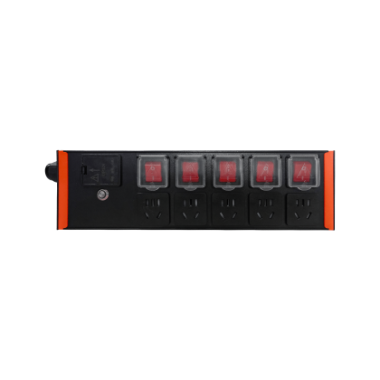
Individual-outlet Pdu Setup For A Security Closet

Made by jrasdop803 / Security / IoT
About the project
A practical note on powering a small security closet or access-control cabinet with an individual-outlet PDU: how to plan loads, label circuits, and remotely reboot a hung controller or gateway without taking the rest of the cabinet offline.
Project info
Difficulty: Easy
Estimated time: 3 hours
License: Creative Commons Attribution CC BY version 4.0 or later (CC BY 4+)
Items used in this project
Hardware components

Hand tools and fabrication machines
Story
Small access-control cabinets are easy to under-plan. A lock controller, a network gateway, a PoE injector or small switch, and maybe a modem all end up on one power strip. When one device locks up, the usual fix is to pull the whole strip — and that takes the door controller down with it.
An individual-outlet PDU is a better fit than a basic strip when you need to power-cycle one device without touching the others.
Why individual outlets matter here
In a closet, some loads should stay up: the access controller that keeps the door operating, and often the local network path that lets you reach it. Other loads — a gateway, an encoder, or a workstation that only talks to the controller — are the ones that hang and need a reboot.
With separately controlled outlets you can:
- Keep the door controller on its own channel
- Put the gateway or other "reboot often" device on another
- Leave spare channels for a future switch, modem, or programmer laptop supply
- Power-cycle one outlet remotely if you cannot stand in front of the cabinet
This is about recovery and discipline, not about metering. If you need per-outlet current readings, look for a different class of PDU; many compact Wi-Fi units, including the example below, do not advertise metering.
Example hardware used in this note
This note uses the UNI-PDU-FK-5 as a concrete example of a compact, individually controlled unit:
- 5 individually controlled channels
- 100-250V AC
- 2.4 GHz Wi-Fi (IEEE 802.11 b/g/n)
- Aluminium housing, 90.0 × 363.0 × 45.0 mm
- 3-pin plug mounting
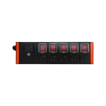 Product details are on the UNI-PDU-FK-5 page
The housing is long and shallow (363.0 × 45.0 mm in the long and depth directions), which is useful on a cabinet wall or a shallow shelf. Confirm that the enclosure has clearance for the plugs and cable bend radius, not just the housing itself.
Power planning
Before you hang the PDU, work through the following.
List every device in the cabinet and whether it must stay up during a reboot of something else. A typical split is: door controller and maybe the PoE switch on "keep-alive" outlets; gateway, video encoder, or programming laptop brick on "rebootable" outlets.
Check nameplate current or wattage for each load and add them up against the upstream circuit, usually a general-purpose receptacle feeding the closet. The example PDU accepts 100-250V AC; that does not replace checking the branch circuit or the plug rating. Do not assume the five outlets can each run a high-draw load at once just because there are five of them.
Avoid putting the PDU itself on a timer or a switched outlet you might turn off by accident. If the PDU is how you recover a hung gateway, it needs a stable upstream feed.
Give the PDU its own 2.4 GHz path that will still be reachable if the cabinet's local gateway is down. If the only Wi-Fi in the room is the gateway you might need to reboot, you cannot reach the PDU when you need it most. A nearby access point that does not depend on that gateway is the safer pattern.
After install, test a remote reboot of a non-critical outlet before you rely on it.
Labeling
Label both ends: the outlet on the PDU and the cable or device. In a tight closet you will not remember which of five identical cords is the controller six months later.
A workable scheme is: Outlet 1, access controller (do not remote-cycle except as a last resort); Outlet 2, network switch or PoE injector; Outlet 3, building or controller gateway (the usual reboot target); Outlet 4, spare or modem; Outlet 5, spare or service laptop.
Write the same names in the PDU's configuration interface if it lets you rename channels, and on a paper legend inside the cabinet door. Include the upstream breaker ID on the legend.
Remote reboot of a controller or gateway
The useful workflow is: confirm the device is actually wedged (not just a stale dashboard), cycle only its outlet, wait long enough for boot, then confirm the service is back. Leave the access controller alone unless the door system itself is the one that is stuck.
Watch for boot time: a gateway can take a few minutes, so do not cycle it twice in a row. Watch shared dependencies: if the gateway and the controller share a switch on a third outlet, cycling the switch will take both down.
The PDU's management path should not ride only on the device you are about to reboot. Also know how to power the critical controller locally if the PDU or its network path fails.
What this does not do
This is not a substitute for a UPS if you need ride-through during a building power blip. It is also not a metered PDU: do not use it as a current monitor or for per-outlet energy accounting unless the datasheet for your exact unit says it supports that.
The point is narrower and still worth doing: in a small security closet, separately controlled outlets let you plan, label, and recover one device without taking the door or the rest of the cabinet down with it.
Credits
Related products



Leave your feedback...