
Humidity And Temperature Measurement Using Arduino

Made by hIOTron / Productivity / IoT
About the project
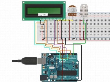
In this project, we are going to calculate the surrounding temperature and humidity and the same will display it on a 16x2 LCD screen.
Project info
Difficulty: Moderate
Platforms: Arduino
Estimated time: 1 hour
License: GNU General Public License, version 3 or later (GPL3+)
Items used in this project
Hardware components


Story
About Project
A mixed temperature and humidity sensor DHT11 is utilized with Arduino uno to develop this project.
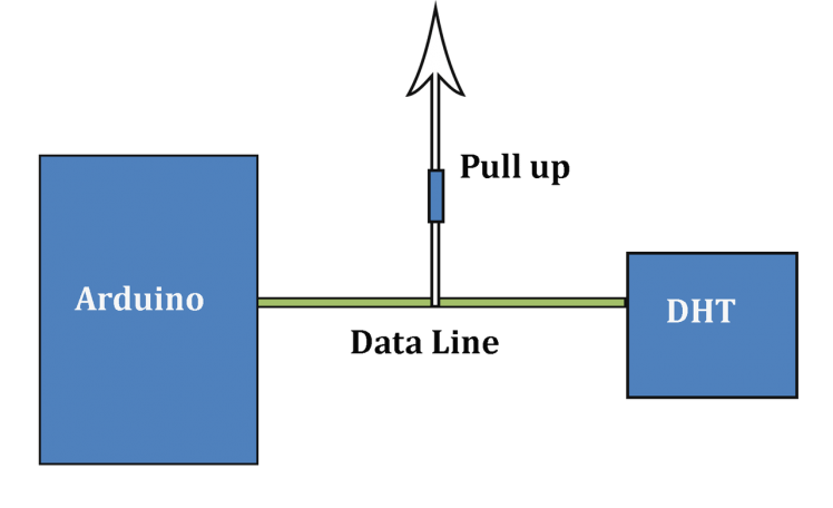
Working of this project depends on single-wire serial communication. The first Arduino transmits a start signal to the DHT module and then DHT presents a response signal including temperature and humidity data. Arduino gathers and removes in two parts one is humidity and the second one is temperature and then sends them to 16x2 LCD.
In this project, we have utilized a sensor module DHT11. The DHT11 sensor module is a linked module for sensing humidity and temperature which presents a calibrated digital output signal.
DHT11 delivers us a specific value of humidity and temperature and assures high security and long term immobility. DHT11 module operates on serial communication. This module transfers data in the form of the pulse train of a specific time period. Before sending data to Arduino it requires some initialize command with a time delay. And the whole process time is about 4ms. Entire data transmission is of 40-bit and data format of this process is given below:
Complete Process
Firstly, Arduino sends a high to low start signal to DHT11 with 18µs delay. And then Arduino pull-up the data line and waits for 20-40µs for DHT’s response (as shown below). Once DHT recognizes starts signal, it will send a low voltage level response signal to Arduino of time delay about 80µs. After that DHT controller pulls up the data line and holds it for 80µs for DHT’s arranging of transmitting data.
When a data bus is at a low voltage level which means that DHT11 is transmitting a response signal. Once it is done, DHT again presents a data line pull-up for 80µs for preparing data transmission.
The data format that is transmitting by DHT to Arduino for every bit starts with 50µs low voltage level and length of high voltage level signal defines whether a data bit is “0” or “1”.
Internet Of Things Course Training will help you to learn all about such various IoT Devices.
Code
Credits
Related products


Leave your feedback...