
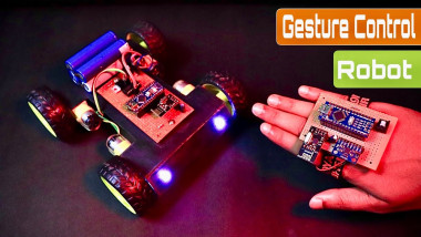
How To Make Arduino Gesture Control Robot At Home

Made by rau7han
About the project
Hi readers, welcome back to another interesting project, in this project, I will show you How To Make an Arduino Gesture Control Robot
Items used in this project
Hardware components

Story
Hi readers, welcome back to another interesting projects, in this project I will show you How To Make Arduino Gesture Control Robot At Home Using Radio Module in a very easy way.
To begin with let me go through features of this project! Like the usual radio controlled cars that run with a remote this robotic car is remote less!
I mean it does not have a remote or a control button to move up, down, right and left.
Instead this project has the advance feature of gesture, you will be controlling the car with the gestures of your hand.
How cool is that controlling something with the gestures of your hand that too with the project you could make at home.
With this being said let us see how you can build this project, like always I have also included the complete instructions on building this project along with the circuit diagram and codes.
Supplies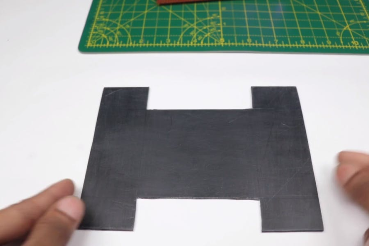
- Piece of Cardboard
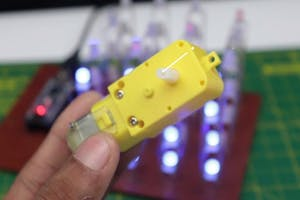
- BO motor and wheels
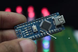
- Arduino Nano
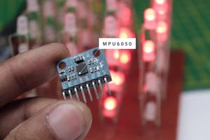
- Gyro sensor or MPU6050
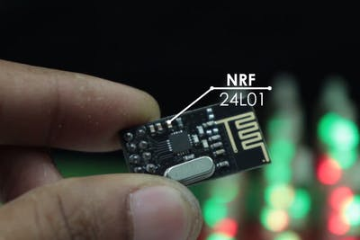
- NRF 24L01
- Tip 32c Transistor
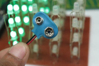
- 9v Battery and Holder
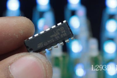
- L293D servo motor driver
- Hot Glue
- Empty PCB
- Band for Wrist
Double-sided tape
- LED lights(Optional)
- Soldering Iron
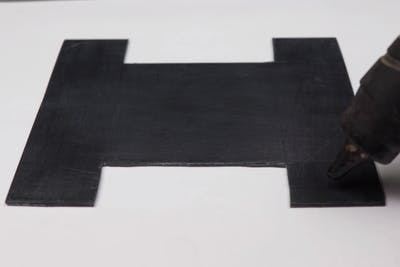
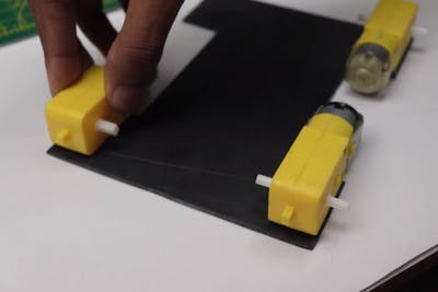


To support the four wheels and BO motor I will be using a piece of cardboard.
You can cut the shape of the cardboard as you can see in the images above, if the size of your wheels is big you might need to make some modifications.
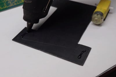
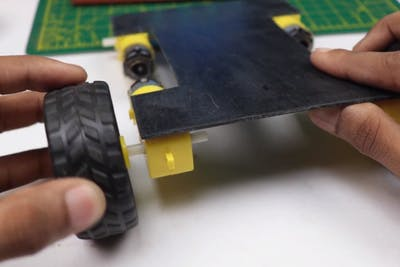
Once you have that shape we can start assembling BO motor to this cardboard.
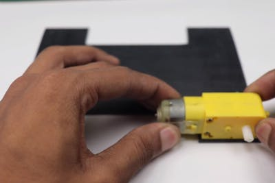
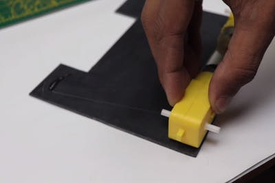
Add a drop of HOT Glue and place theBO motor, Make sure the hot glue is not too hot otherwise, it may melt the plastic of the motor case.
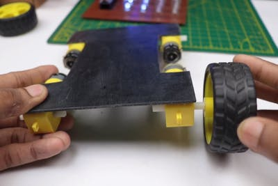
Repeat the same steps for theother side as well after you have all the BO Motors ready you can attach wheels.
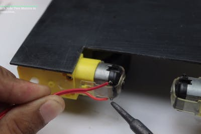
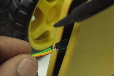
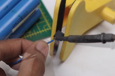
Now we can solder the wire to theBO motor if it does not have pre-soldered wires.
My ends of the wire were from the socket that I found useful for this project, it's a connecting wire that can be connected to male-type pins with ease.
Transmitter Circuit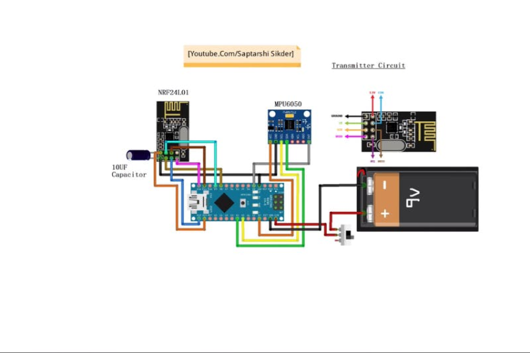
If you're considering creating a printed circuit board (PCB) for your electronic project, NextPCB stands out as an excellent option. NextPCB boasts extensive experience as a leading PCB manufacturing company in China, specializing in PCB prototyping and fabrication.
Their services include comprehensive PCB assembly, complete with global free shipping, and adherence to ISO9001 quality control standards.
Additionally, their website offers a convenient online Gerber viewer, allowing you to easily upload your Gerber and drill files to visualize your PCB design.
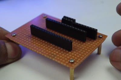
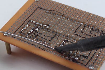
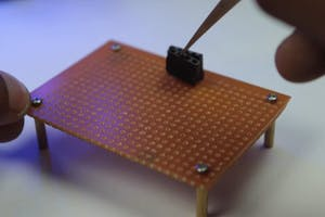
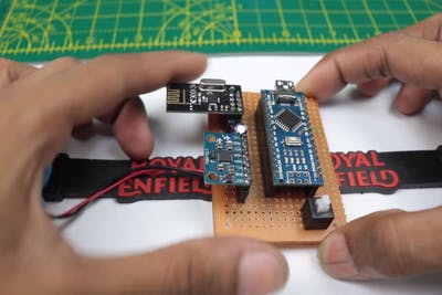
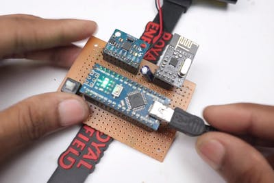
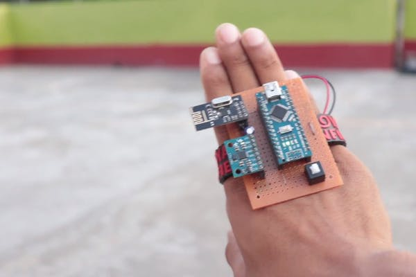
Here will be using a zero PCB to hold the components and make a circuit.
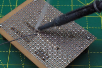
I will start by soldering the slot to hold the Arduino Nano board, This is an easy process if you have some hands-on experience in soldering, if not you might need to take the supervision of an expert.
The other way is you can make the circuit on a breadboard but it makes the project too complex.
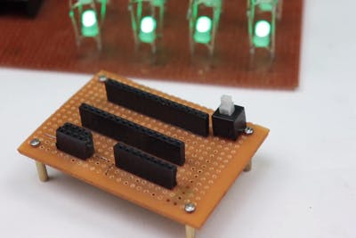
After the Arduino slot make aslot to hold the NRFL201 module as well for the MPU6050.
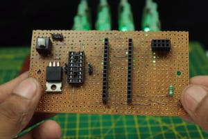
End of the process you will have a ready transmitter circuit, all it is missing is codes that is essential for working.
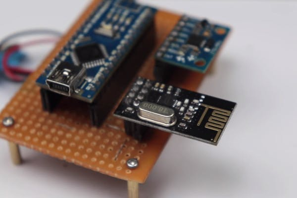
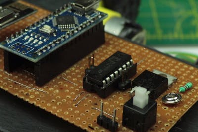
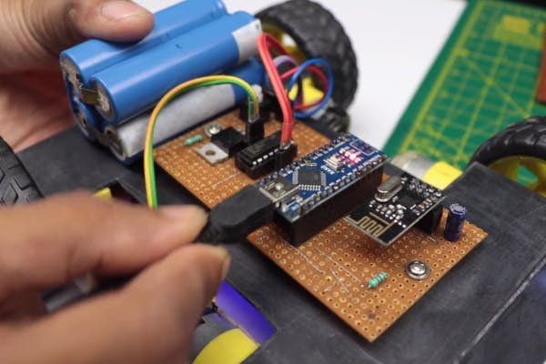
Receiver Circuit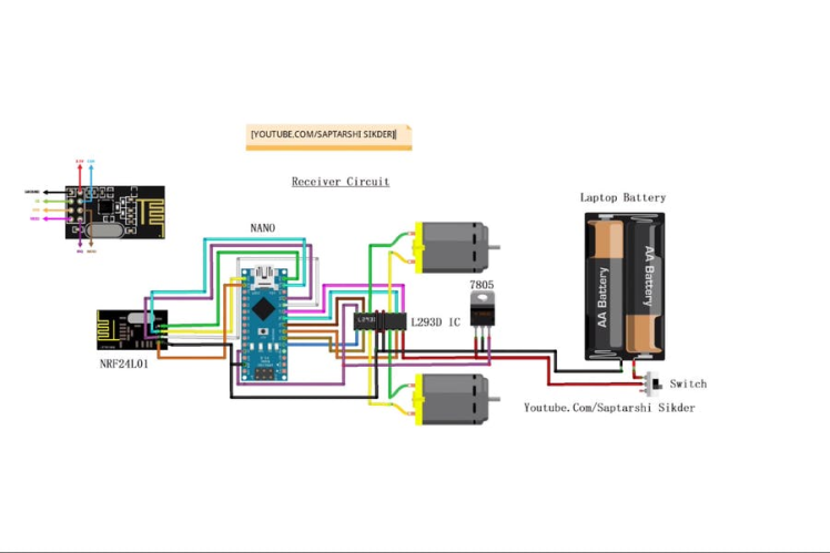

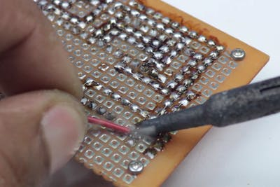
Even here the process is thesame but here you have the liberty to choose a much larger empty PCB this will be installed on the car so the problem of space usage does not bother you much.
Start by soldering slots on an empty PCB where the components will be added later, Then add the transistor and motor drive to thePCB directly.
Follow the circuit to make connections, if you miss any the problem of reworking will waste your time.
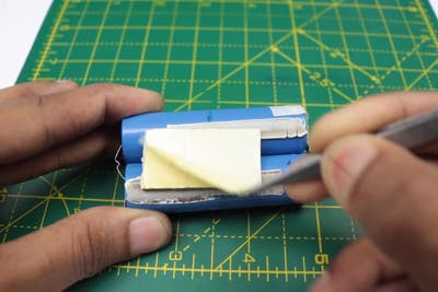
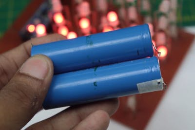
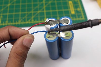
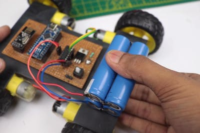
To power this board I will use rechargeable batteries that I recycled from my old laptop.
I used aset of 4 that were soldered together as a pair of 2 to power the entire circuit for a long time.
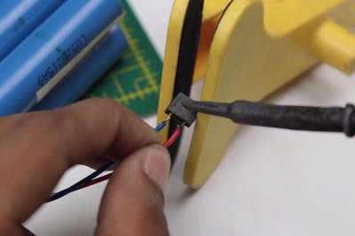
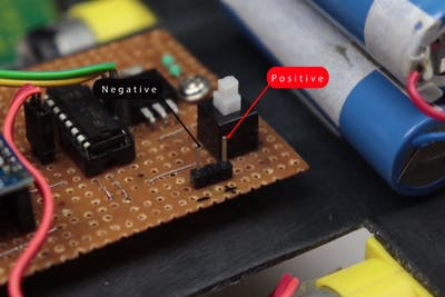
The end of the battery was soldered with the slot that would fit the connecting pins.
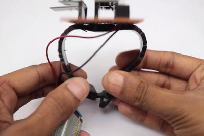
Finishing the Circuit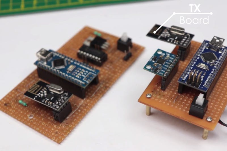
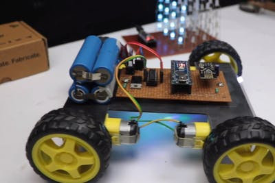
Now that we have the circuits of both the transmitter and receiver ready we will complete the circuit by adding apowering source.
The battery pack that I prepared earlier is added to the frame of the car, I will be using double side adhesive to hold the battery pack.
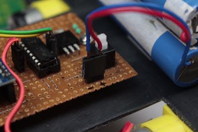
Then connect the terminals of the battery to the circuit board pin.
End of this process we will have the car ready, Theonly one thing pending now is the codes for this robot.
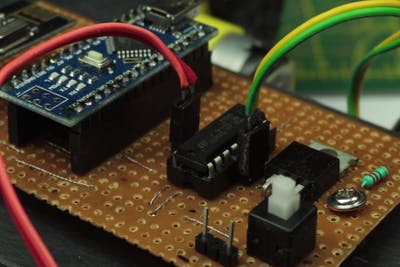
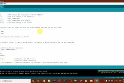
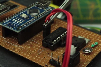
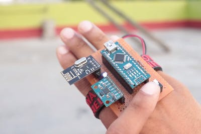
Programming and Setting the Transmitter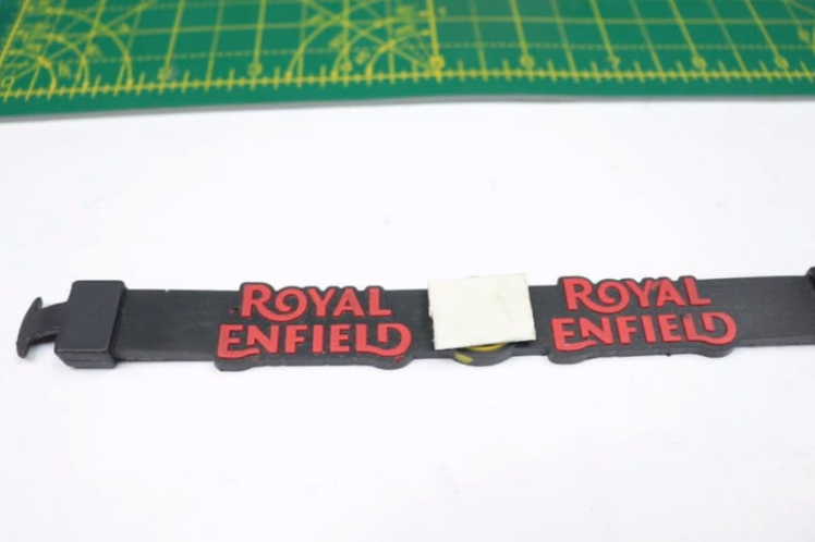
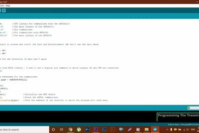
This is the control panel in our project the button are made from integrated circuit as I can define.
Here the small motion sensor inside the gyro sensor also known as MPU6050 controls the entire car movement.
This motion has to be converted to specific commands to be able to read by the Arduino and finally send as radio wave to the receiver.
This task will be done by the Arduino code, copy and paste the below code on your Arduino IDE, after the code is uploaded the receiver is ready for using, now disconnect the USB cable and connect the 9v battery.
I have installed this transmitter on a wrist band that was adjustable so that it can fit any wrist
#include <SPI.h>        //SPI library for communicate with the nRF24L01+
#include "RF24.h"       //The main library of the nRF24L01+
#include "Wire.h"       //For communicate
#include "I2Cdev.h"     //For communicate with MPU6050
#include "MPU6050.h"    //The main library of the MPU6050


//Define the object to access and cotrol the Gyro and Accelerometer (We don't use the Gyro data)
MPU6050 mpu;
int16_t ax, ay, az;
int16_t gx, gy, gz;

//Define packet for the direction (X axis and Y axis)
int data[2];

//Define object from RF24 library - 9 and 10 are a digital pin numbers to which signals CE and CSN are connected.
RF24 radio(8,9);

//Create a pipe addresses for the communicate
const uint64_t pipe = 0xE8E8F0F0E1LL;

void setup(void){
  Serial.begin(9600);
  Wire.begin();
  mpu.initialize();              //Initialize the MPU object
  radio.begin();                 //Start the nRF24 communicate
  radio.openWritingPipe(pipe);   //Sets the address of the receiver to which the program will send data.
}

void loop(void){

  //With this function, the acceleration and gyro values of the axes are taken.
  //If you want to control the car axis differently, you can change the axis name in the map command.
  mpu.getMotion6(&ax, &ay, &az, &gx, &gy, &gz);

  //In two-way control, the X axis (data [0]) of the MPU6050 allows the robot to move forward and backward.
  //Y axis (data [0]) allows the robot to right and left turn.
  data[0] = map(ax, -17000, 17000, 300, 400 ); //Send X axis data
  data[1] = map(ay, -17000, 17000, 100, 200);  //Send Y axis data
  radio.write(data, sizeof(data));
}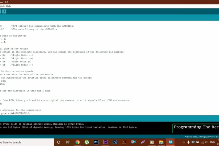

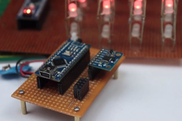
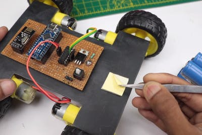
In the project the car will be controlled by a receiver, Receiver is nothing but the slave Arduino.
We are using the concept of master slave electronics in our project, This Arduino code converts the signals from the transmitter module to meaningful signals that will run the dc motors via the motor driver.
You can see the L293D motor driver on the 2nd image of this step.
You can connect the terminals of DC motor/ BO motor to the slot provided.
After which connect the programming cable to the computer and Arduino.
Copy and paste the receiver code on your IDE and hit on the upload button, in some time the receiving part will be ready, all you have to do is connect the battery supply to the circuit.
#include <SPI.h>      //SPI library for communicate with the nRF24L01+
#include "RF24.h"     //The main library of the nRF24L01+

//Define enable pins of the Motors
const int enbA = 2;
const int enbB = 7;

//Define control pins of the Motors
//If the motors rotate in the opposite direction, you can change the positions of the following pin numbers
const int IN1 = 3;    //Right Motor (-)
const int IN2 = 4;    //Right Motor (+)
const int IN3 = 5;    //Left Motor (+)
const int IN4 = 6;    //Right Motor (-)

//Define variable for the motors speeds
//I have defined a variable for each of the two motors
//This way you can synchronize the rotation speed difference between the two motors
int RightSpd = 130;
int LeftSpd = 150;

//Define packet for the direction (X axis and Y axis)
int data[2];

//Define object from RF24 library - 9 and 10 are a digital pin numbers to which signals CE and CSN are connected
RF24 radio(8,9);

//Create a pipe addresses for the communicate
const uint64_t pipe = 0xE8E8F0F0E1LL;

void setup(){
  //Define the motor pins as OUTPUT
  pinMode(enbA, OUTPUT);
  pinMode(enbB, OUTPUT);
  pinMode(IN1, OUTPUT);
  pinMode(IN2, OUTPUT);
  pinMode(IN3, OUTPUT);
  pinMode(IN4, OUTPUT);

  Serial.begin(9600);
  radio.begin();                    //Start the nRF24 communicate
  radio.openReadingPipe(1, pipe);   //Sets the address of the transmitter to which the program will receive data.
  radio.startListening();
  }

void loop(){
  if (radio.available()){
    radio.read(data, sizeof(data));

    if(data[0] > 380){
      //forward
      analogWrite(enbA, RightSpd);
      analogWrite(enbB, LeftSpd);
      digitalWrite(IN1, HIGH);
      digitalWrite(IN2, LOW);
      digitalWrite(IN3, HIGH);
      digitalWrite(IN4, LOW);
    }

    if(data[0] < 310){
      //backward
      analogWrite(enbA, RightSpd);
      analogWrite(enbB, LeftSpd);
      digitalWrite(IN1, LOW);
      digitalWrite(IN2, HIGH);
      digitalWrite(IN3, LOW);
      digitalWrite(IN4, HIGH);
    }

    if(data[1] > 180){
      //left
      analogWrite(enbA, RightSpd);
      analogWrite(enbB, LeftSpd);
      digitalWrite(IN1, HIGH);
      digitalWrite(IN2, LOW);
      digitalWrite(IN3, LOW);
      digitalWrite(IN4, HIGH);
    }

    if(data[1] < 110){
      //right
      analogWrite(enbA, RightSpd);
      analogWrite(enbB, LeftSpd);
      digitalWrite(IN1, LOW);
      digitalWrite(IN2, HIGH);
      digitalWrite(IN3, HIGH);
      digitalWrite(IN4, LOW);
    }

    if(data[0] > 330 && data[0] < 360 && data[1] > 130 && data[1] < 160){
      //stop car
      analogWrite(enbA, 0);
      analogWrite(enbB, 0);
    }
  }
}
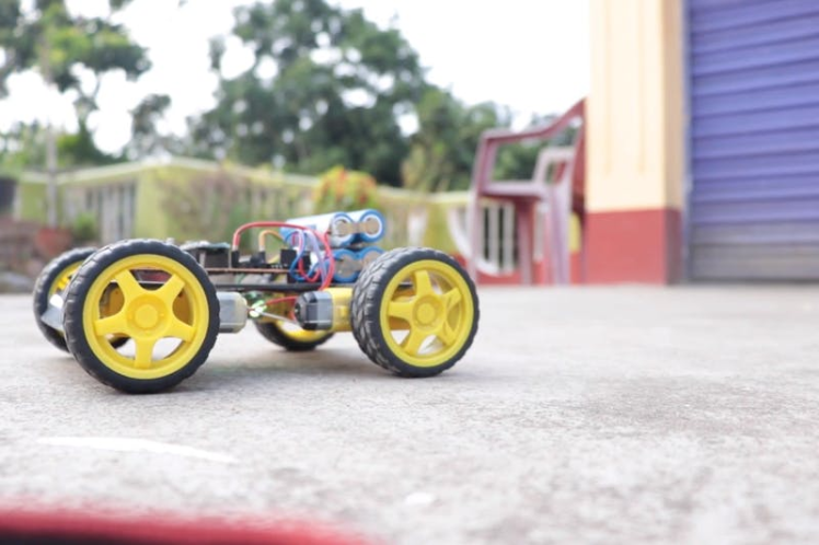
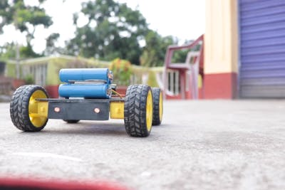
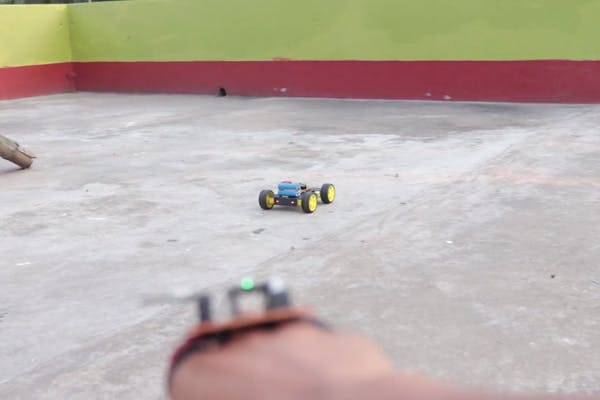
Using this gesture control robot is very easy, Just connect the batteries to both Car and the remote(transmitter on hand)
The transmitter will be fit in your and will work as a remote control but without any buttons.
When you move your hand to that direction the change in orientation will be detected by the gyroscopic sensor and according to the movement the Arduino board from Tx or transmitter sends a signal to the receiver board found in the Robotic car and because of this, your robot moves as per your hand gestures.
This is a very fun toy to play with if you are an electronics lover.
The backup time of this robot is very high so you can enjoy itfor quite a long time.
Code
Credits
Related products


Leave your feedback...