
How to Make a Neopixel Rainbow Clock

Made by mr-x
About the project
let's build a beautiful desktop clock using Arduino and neopixel
Project info
Difficulty: Difficult
Platforms: Adafruit, Seeed Studio, SparkFun
Estimated time: 1 hour
License: Creative Commons Attribution CC BY version 4.0 or later (CC BY 4+)
Items used in this project
Hardware components

Story
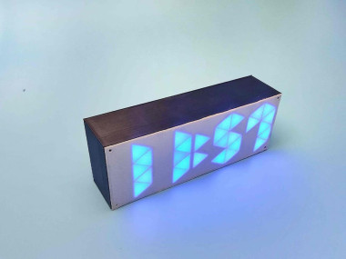
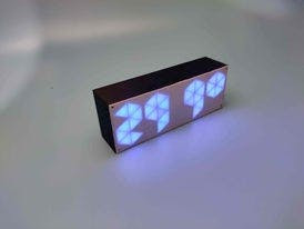
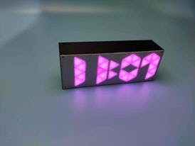
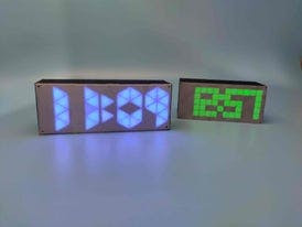
I know making a clock sounds a little irrelevant, especially nowadays because we all have smartphones and no one is going to use or look into the clock for time, but it is good when you are doing some work or during a workout. So, I decided to make one Arduino digital clock for my room. While searching for the clock model, I got thousands of designs but most of them used seven-segment displays and I wanted to build a unique and colourful clock without using Seven segment displays. So, here I am going to use Neo-Pixel LEDs with Arduino pro mini and RTC module. About the clock I made, it's a very simple clock that shows time and room temperature and the main feature of this clock is that the colour of the digits changes every minute.
COMPONENTS NEEDED FOR MAKING THE 10-segment CLOCK
- Arduino Pro Mini
- DS3231 RTC Module
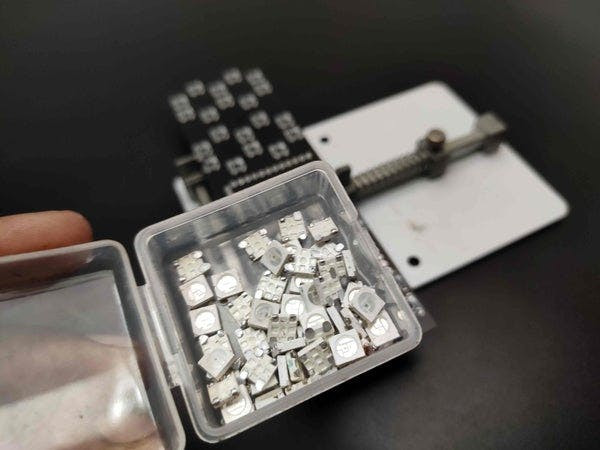
- WS2812 Neo pixel LEDs- 42nos
- 2× Push Button
- Switch
- AMS1117 Voltage Regulator
- 330-ohm Resistor
- 3D printed structure
- 3.7v li-ion battery
- TP4056 charging module
- MT3608 booster module
The working of this clock is very simple and similar to other digital clocks. This clock gets the current time and date using the DS3231 RTC module and then this time is displayed on Neo-Pixel LEDs using Arduino Pro Mini. The DS3231 is a low-cost, accurate Real Time Clock that can maintain hours, minutes, and seconds, as well as, day, month, and year information. The module uses the I2C communication protocol which makes the connection to the Arduino board very easy. However, when it comes to communication between Arduino and RTC module the code isn’t that small and easy. But there are already several libraries for the DS3231 RTC which can be found on the internet. with the help of such libraries, we can read the current time, and with the help of Arduino, we can display that time in any type of display. DS3231 RTC module also comes with a temperature sensor so, we can also get the temperature readings.
10-Segment Rainbow Clock Circuit Diagram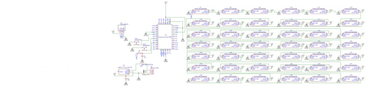
As you can see, this circuit diagram has two parts, first one is the main circuit that consists of an Arduino Pro Mini, DS3231 RTC module, push buttons, and AMS1117 voltage regulator and the second is the LED digit circuit where all the Neo-Pixel LEDs are arranged to display the time. DS3231 works on the I2C communication protocol so the SCL and SDA pins of the RTC module are connected to I2C pins (A4 and A5) of Arduino. The push buttons are connected to digital pin 2 and 4 of Arduino. This complete setup is powered by two 18650 cells connected in series. The output voltage from these cells will be around 7.4 so an AMS1117 5V voltage regulator is used to supply regulated 5V to Arduino pro mini and other components.
download the circuit from here
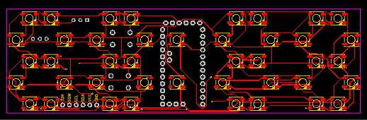
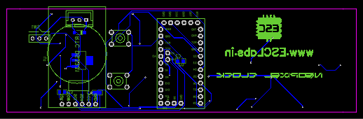
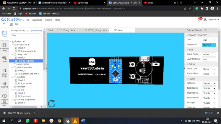
PCB designingyou can see that our circuit has 42 led and some more components. building the circuit in a common PCB is very difficult and time killing so I decided to make a PCB for the circuit. so I converted the circuit diagram into a PCB on easyeda.com. then I designed the PCB.after designing I downloaded the Gerber files for PCB fabrication.
After downloading the Gerber file I went to jlcpcb.com. jlcpcb provides 5PCBs for just 2$ and their PCB Assembly starts from 0$
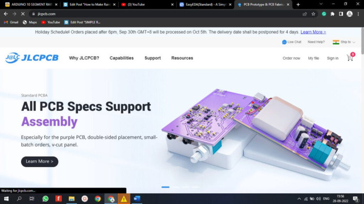
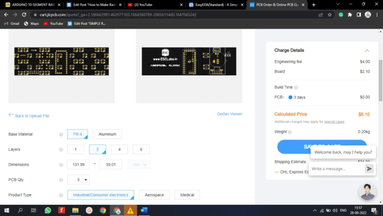
To order PCBs just click order now and upload the Gerber file. after uploading the Gerber file we can select the PCB parameters like silkscreen colour, thickness, quantity etc. after that select the shipping method and finally place the order
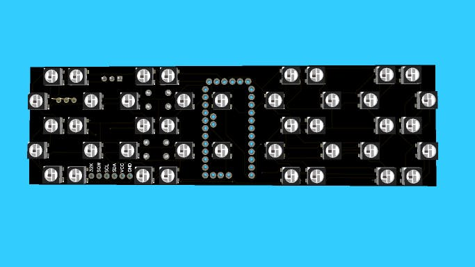
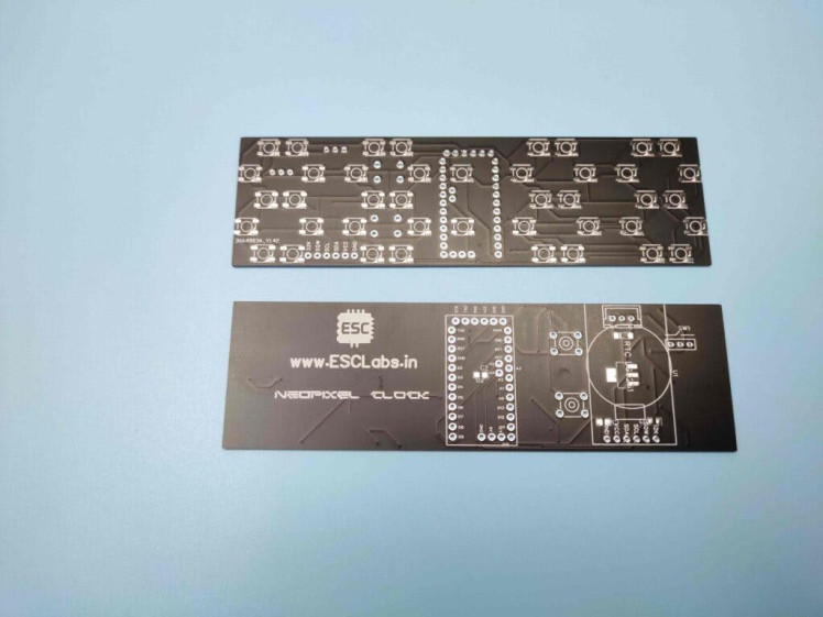
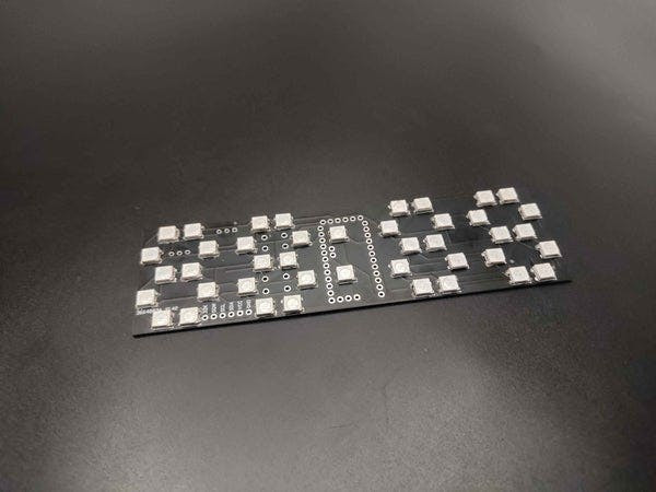
Fabricated PCBs From JLCPCBAfter two weeks I received the PCBs from jlcpcb. The PCBs are good-looking and the quality is superb
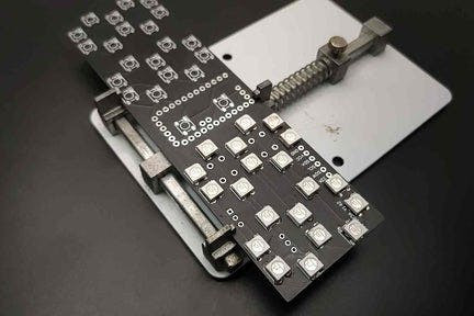
We need to solder 42 Neopixel LEDs to the PCB. Doing this by hand is painful so I decided to go with the reflow method. first, I dispensed the solder paste using a syringe. After that, I placed Neopixel LEDs one by one. In the first step, I placed only half of the LEDs. Now I placed the PCB on my Diy reflow plate. And cooked the PCB. Here is the PCB after reflow soldering. everything is just okay.
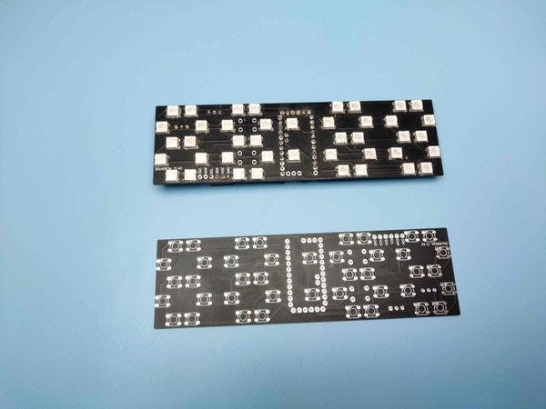
So I repeated the process for the remaining LEDs. After the led soldering let's solder the other components. First I placed the small SMD components and soldered them with my normal soldering iron. Then I placed and soldered the female header pins for the Arduino pro mini. finally, I attached the buttons to the P


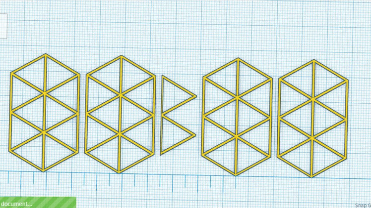
As discussed earlier, instead of using a 7-segment display we are going to use Neo-Pixel LEDs for displaying time. Here, we are going to 3-D print some parts so that we can arrange the Neo-Pixel LEDs in digits form and display time. After hours of thinking and calculations, I designed a ten-segment digit. The design is very simple, each segment has a slot for Neo pixel LED. Later in these slots, we will place Neo pixel LEDs. I also designed two segments for the second indication. Then I joined 4 digits and the second indicator to a common base and made the enclosure to enclose everything. I have designed all the parts in Tinker CAD software. Once it was done, my design looked something like this:
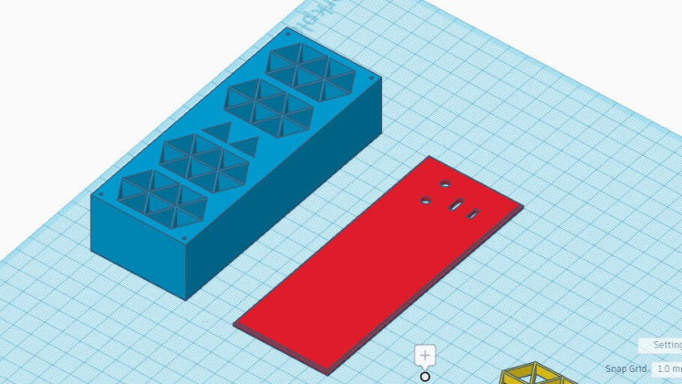
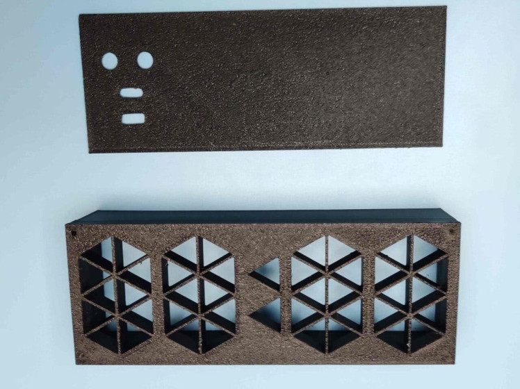
After I was satisfied with the design, I exported it as an STL file, sliced it based on printer settings, and finally printed it. The STL file is also available for download and you can print your casing using it.
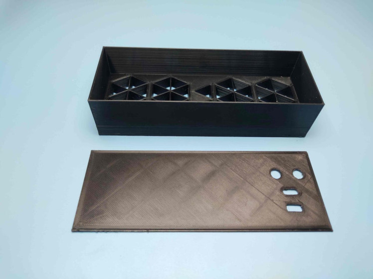
download the 3d files from here
Assembling the Neopixel clock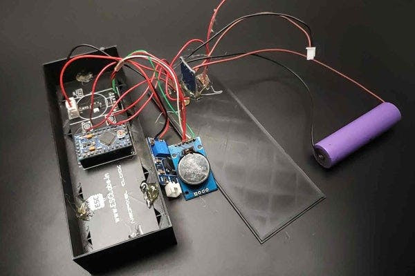
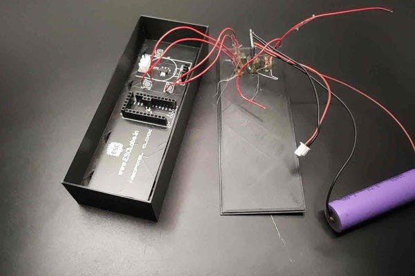
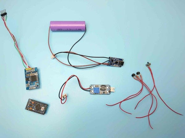
Here I am using a 3.7v li. ion battery a with TP4056 charging circuit. Also a booster circuit. Now let's assemble. I placed buttons, switches and a charging module on the socket of the back cover and secured it with the glue gun. Then I placed the PCB on the main case. After that, I connected the battery to the circuit. Now it's time to place the Arduino after programming. And finally, I placed the RTC module on its socket. And closed everything.
Arduino ProgrammingAs I mentioned earlier, the code for this project is not very simple. Honestly, I referred to lots of other clock projects to make this code. Whatever, the complete code is given at the end of the document. Here, I am explaining the complete code line by line.
First, I included the required libraries. In this project, we are using the ds3231 RTC library to control the DS3232RTC module. DS3232RTC is an Arduino library that supports the Maxim Integrated DS3232 and DS3231 Real-Time Clocks. The DS3232RTC library also implements functions to support the additional features of the DS3232 and DS3231. Time and Timelib libraries provide timekeeping functionality for Arduino. Wire library allows communication with I2C(DS3231) devices. And finally, I am using FastLED to control the neopixel LEDs
#include <DS3232RTC.h>
#include <TimeLib.h>
#include <Time.h>
#include <Wire.h>
#include <FastLED.h>
Next, I defined the total number of LEDs, colour order of LED type, Arduino pin for data input, and push-button pins.
#define NUM_LEDS 42
#define COLOR_ORDER RGB
#define LED_PIN 6
#define MIN_PIN 4
#define HUR_PIN 2
Also, I made a byte array for the numbers and symbols. We have a total of 10 LEDs in each digit and a total of 12 characters (0-9 numbers + Degree symbol and C letter) each array represents each character. For example {1, 1, 0, 1, 1, 1, 1, 0, 1, 1} represents zero that is in our digit segment 3 and segment 8 in off-stage all other LEDs in on stage that will display zero and so on…
byte digits[12] [10] = {
{1,1,0,1,1,1,1,0,1,1},
{1,1,1,1,1,0,0,0,0,0},
{1,0,1,1,1,1,0,1,1,1},
{1,1,1,1,1,1,0,1,0,1},
{1,1,1,1,0,1,1,1,0,0},
{1,1,1,0,1,1,1,1,0,1},
{1,1,1,0,0,1,1,1,1,1},
{1,1,1,1,1,1,1,0,0,0},
{1,1,1,1,1,1,1,1,1,1},
{1,1,1,1,1,1,1,1,0,0},
{1,1,1,1,1,1,1,1,0,0},
{0,0,1,1,1,1,1,1,0,0}};
Next, I defined the color table you can customize this according to your ideas.
long ColorTable[21] = {
CRGB::Amethyst, //white
CRGB::Aqua, //pink
CRGB::Blue, //Blue
CRGB::Chartreuse,// Gold
CRGB::DarkGreen, //Red
CRGB::DarkMagenta,//Aqua
CRGB::DarkOrange, // yellow green
CRGB::DeepPink, //Aqua
CRGB::Fuchsia, //Sea blue
CRGB::Gold, //Gold
CRGB::GreenYellow,//off white
CRGB::LightCoral,//white
CRGB::Tomato,//white
CRGB::Salmon,//Pure white
CRGB::Red,// Drak Green
CRGB::Orchid,//blue white
CRGB::Sienna,//yellow white
CRGB::Purple,// aqua
CRGB::DarkOrange,//yellow green
CRGB::FloralWhite,//white
CRGB::Yellow //yellow
};
In the setup section first, I started the serial monitor and I2C communication using serial.begin and wire.begin respectively. Here, we use the serial monitor for testing the code and circuit. Also, I defined the mode of all pins here we are using button pins are as input and data pin as output and in the case of input, I used the input pull-up function to pull high pin status.
void setup(){
Serial.begin(9600);
Wire.begin();
FastLED.addLeds<WS2812B, LED_PIN, RGB>(leds, NUM_LEDS);
pinMode(DST_PIN, INPUT_PULLUP);
pinMode(MIN_PIN, INPUT_PULLUP);
pinMode(HUR_PIN, INPUT_PULLUP);
}
Then I read the time using the RTC.read function and stored it into a DateTime object. Also, I converted the 24-hour format into a 12-hour format.
GetTime(){
tmElements_t Now;
RTC.read(Now);
int hour=Now.Hour;
int minute=Now.Minute;
int second =Now.Second;
if (second % 2==0)
{Dot = false;}
else {Dot = true;};
if (hour >= 12) {
hour -= 12;
}
Next, I defined two arrays that are timetoarray and temptoarray for displaying the current time and temperature in the display. I started from the last LED of digits and displayed 4 digits. I defined the first LED of each digit using the cursor function. In the same way, I displayed the temperature also.
for(int i=1;i<=4;i++){
int digit = Now % 10;
if (i==1){
cursor = 30;
for(int k=0; k<=9;k++){
if (digits[digit][k]== 1){leds[cursor]=ledColor;}
else if (digits[digit][k]==0){leds[cursor]=0x000000;}
cursor ++
};
In the void time function, we can set the time. Here, I used the digital read function of Arduino to read the state of the push button.
void TimeAdjust(){
int buttonH = digitalRead(HUR_PIN);
int buttonM = digitalRead(MIN_PIN);
if (buttonH == LOW || buttonM == LOW){
delay(500);
tmElements_t Now;
RTC.read(Now);
int hour=Now.Hour;
int minutes=Now.Minute;
int second =Now.Second;
if (buttonH == LOW){
if (Now.Hour== 23){Now.Hour=0;}
else {Now.Hour += 1;};
}else {
if (Now.Minute== 59){Now.Minute=0;}
else {Now.Minute += 1;};
};
RTC.write(Now);
}
Finally, in the main loop section, first I checked if the time is modified or not. Then, I updated the LED array according to the time. The same I did to the temperature array. Finally, I displayed the values in digits using fastLED.show function.
Void loop() {
BrightnessCheck();
DSTcheck();
TimeAdjust();
TimeToArray();
TempToArray();
FastLED.show();
if (TempShow == true)
delay (8000);
}
}

download the code from here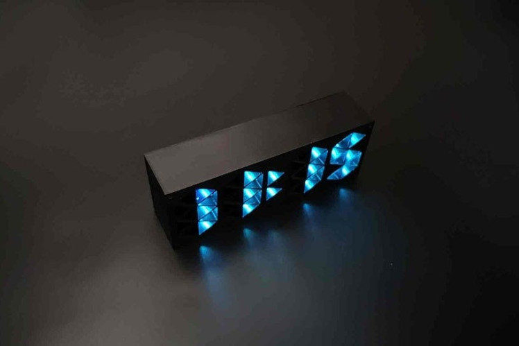

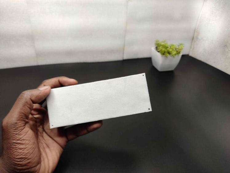
The clock worked just as expected but we can't see the time properly. To solve that again I 3d printed a white sheet. And I glued it to the front of the main case. Now the sheet acts like a diffuser. That's it. our clock is completed now.
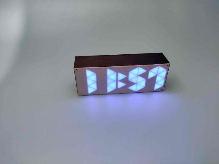
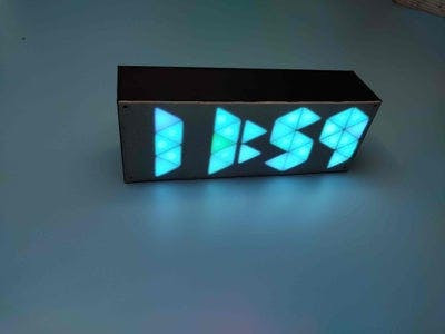
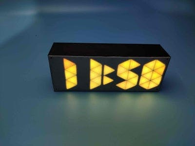
This clock will display of course time and also the temperature. And the main feature is it changes colour in every minute. So this is how I made the 10-segment neopixel clock. Hope you enjoyed and learned something new from here if so follow and subscribe to my channel
Schematics, diagrams and documents
Code
Credits
Related products


Leave your feedback...