
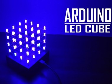
How To Make A 4x4x4 Led Cube Using Arduino

Made by diy-projects-lab / Lights
About the project
In this tutorial I'll show you how to make a 4x4x4 LED cube.
Project info
Difficulty: Moderate
Platforms: Arduino
Estimated time: 1 hour
License: Apache License 2.0 (Apache-2.0)
Items used in this project

Story
In this tutorial I'll show you how to make a 4x4x4 LED cube.
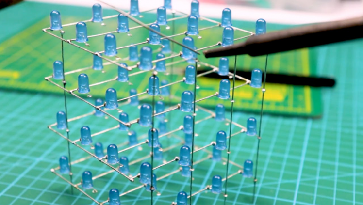
The cube has 64 blue LEDs which make up it's 4 layers(positives) and 16 columns(negatives).
I programed code(sketches) for the Arduino Uno to control the individual LEDs to display patterns for this captivating desktop light show.
This project is successfully completed because of the help and support from Nextpcb
Here are midsummer sales at NextPCB
1. Up to 30% off for PCB oders
2. Up to 20% off for PCBA oders
Only 0$ for 5-10pcs PCB Prototypes https://www.nextpcb.com/
Don't skip this wonderful electronics project because it offers invaluable opportunities for electronic construction and Arduino coding.
visit My website DiY Projects Lab having more than 25 awesome detailed projects
1. Electronics
- Arduino Nano
- 64- 3mm blue LEDs
- Female Headers
- Rainbow Ribbon cable
- 100Ω Resistor
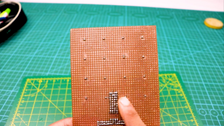
- (OPTIONAL) general purpose prototype board
- PCBs
2. Tools
- Soldering iron.
- Soldering wire.
- Scissors.
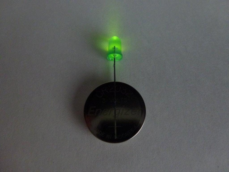
Take the all 64 LEDs and test them to ensure that they all work using a button cell battery
Before we start making our LED cube and solder everything, it’s a good idea to test the LEDs, our LEDs operate at 3.3V, 20mA, we could easily test them using any 3.3v battery, in my case, I used a Lithium-Ion battery to test the LEDs.
Tips:
- the Longer lead is Positive and shorter one is Negative
- DON'T! reverse bias LED, you might damage it.
- DON'T use 5V power supply to test LED.
1 / 2
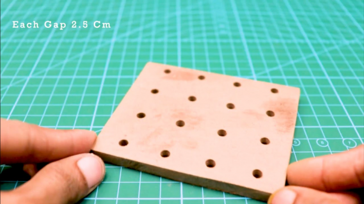
- Find a piece of wood large enough to make a 4x4 grid of 2, 5cm on.
- Draw up a 4x4 grid of lines.
- Make dents in all the intersects with a center punch.
- Find a drill bit that makes holes small enough so that the led will stay firmly in place, and big enough so that the led can easily be pulled out (without bending the wires..).
- Drill the 16 holes.
- Your led cube template is done.
Insert a LED into the individual holes to test the fit. (as you can see in picture)
1 / 3
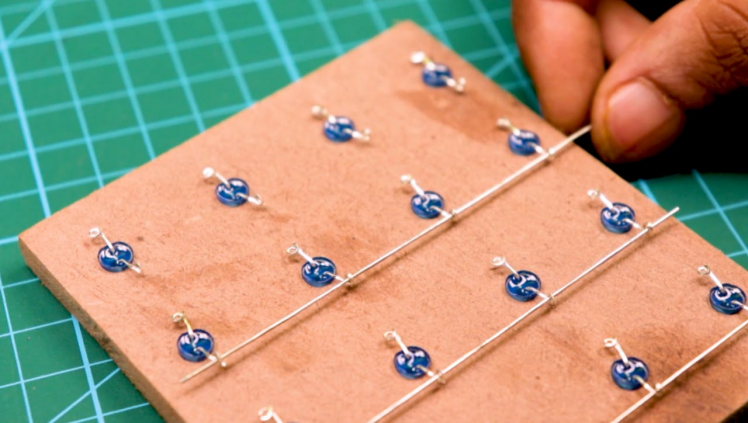
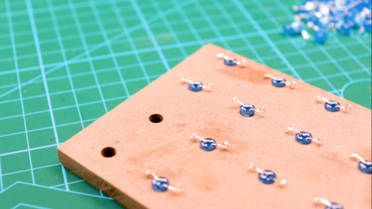
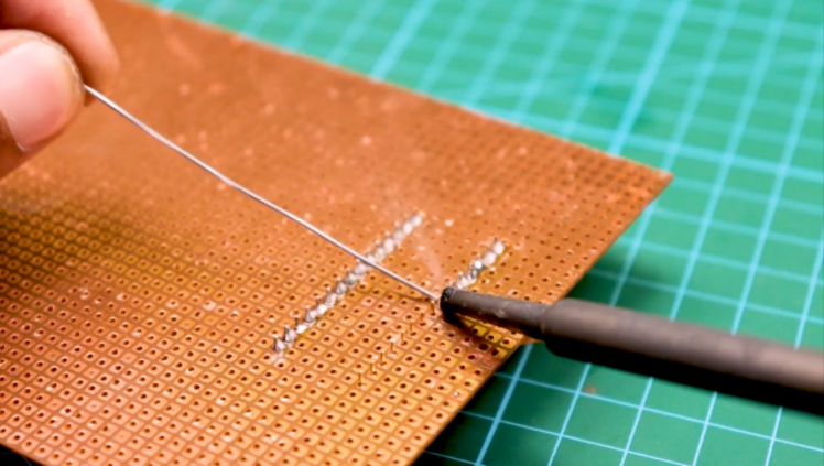
Now that you are geared to solder, follow these steps to solder column layer.
- take the template from the last step.
- start soldering with Negative leads.
- complete one row at time.
- solder the positive leads.
- remove the Column from Template.
- Repeat this process for rest 4 Column Layers

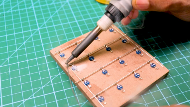
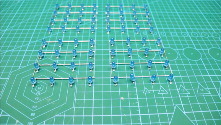
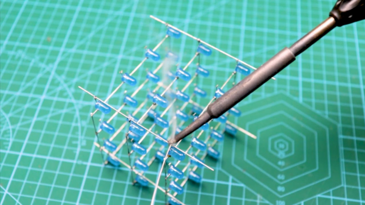
We make the cube in 4 layers of 4x4 leds, then solder them together.Create a layer:
- Put in the LEDs along the back and along one side, and solder them together
- Insert another row of LEDs and solder them together. Do one row at a time to leave place for the soldering iron!
- Repeat the above step 2 more times.
- add cross bracing in the front where the led rows are not connected.
- Repeat 4 times.
1 / 3

Consider a corner LED and that is your reference. Corner towards right becomes your 'x' axis and the other becomes 'y'axis.
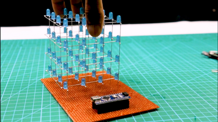
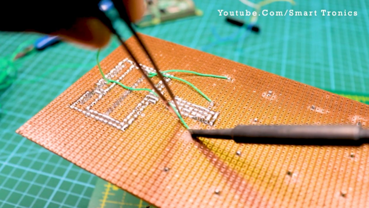
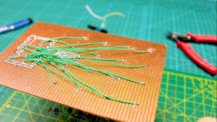
I have named the pins and terminals after connecting on PCB.(Refer to the image)
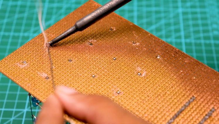
Solder each wire to the terminal strip and hot glue it to avoid the breakage of solder joints.
I made a Small simple wooden casing to hide the wiring. Cut required size ply-wood and hot glue them to form a Box.
The controller.
1 / 6
Guys if you have a PCB project, please visit their website and get exciting discounts and coupons.
The following is the connection details. Example: Pin Name (1, 1) goes to Digital pin 13 on Arduino.
[(x, y)-Pin]
(1, 1)-13
(1, 2)-12
(1, 3)-11
(1, 4)-10
(2, 1)-9
(2, 2)-8
(2, 3)-7
(2, 4)-6
(3, 1)-5
(3-2)-4
(3-3)-3
(3, 4)-2
(4, 1)-1
(4, 2)-0
(4, 3)-A5
(4, 4)-A4
Layers [Layer-Pin]
a-A0
b-A1
c-A2
d-A3
The Code!I found this sketch online, then I edited it to work for my LED cube.
Soon, I'll have my own sketch that will be posted right here, on this i'ble. But for now, if you have any improvements or add-ons to this current sketch, let me know so I can keep it updated:)
Note: The code uploaded here is not Designed by me.
Download the Code and open it in Arduino software.
Connect the arduino to your PC USB port.
Select the Correct Port and your Arduino Board.
Upload the code and your done!
You can power your Arduino using a mobile phone charger.
Working Video and ReferencesCongragulations!!
You made yourself a Cool looking LED CUBE to place on a corner of your Desk..!
Watch the Full working video from here.
Schematics, diagrams and documents
Code
Credits
Related products


Leave your feedback...