
Get Time & Date From The Internet -ethernet Shield & Max7219

About the project
In this tutorial we will learn how to get the date and time from NIST TIME server using Arduino Ethernet Shield and Display it.
Project info
Difficulty: Easy
Platforms: Arduino, Visuino, M5Stack
Estimated time: 1 hour
License: GNU General Public License, version 3 or later (GPL3+)
Items used in this project

Story
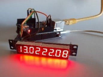
In this tutorial we will learn how to get the date and time from NIST TIME server using Arduino Ethernet Shield and Display it on the MAX7219 8-digit LED Display.
Watch the video!
Step 1: What You Will Need1 / 6

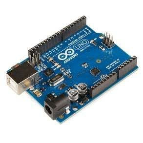
- Arduino UNO (or any other Arduino)
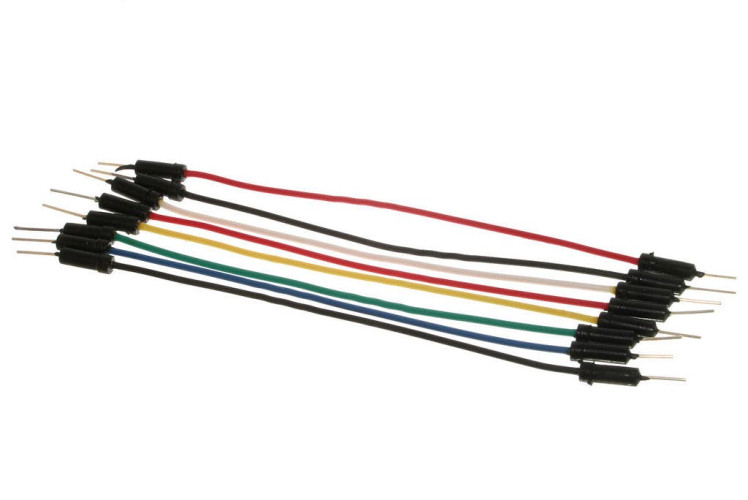
- Jumper wires
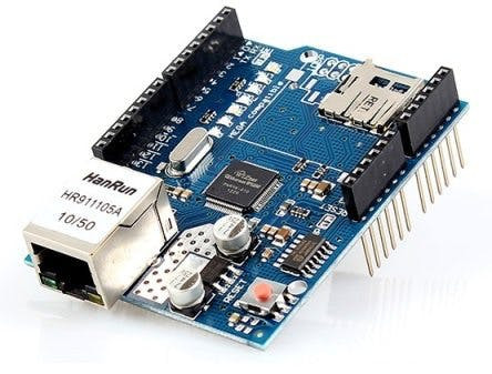
- Ethernet Shield for Arduino
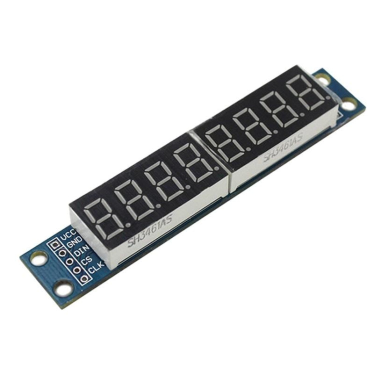
- Max7219 Led Dot Matrix 8-digit Digital Display Control Module
- LAN Internet connection
- Visuino program: Download Visuino
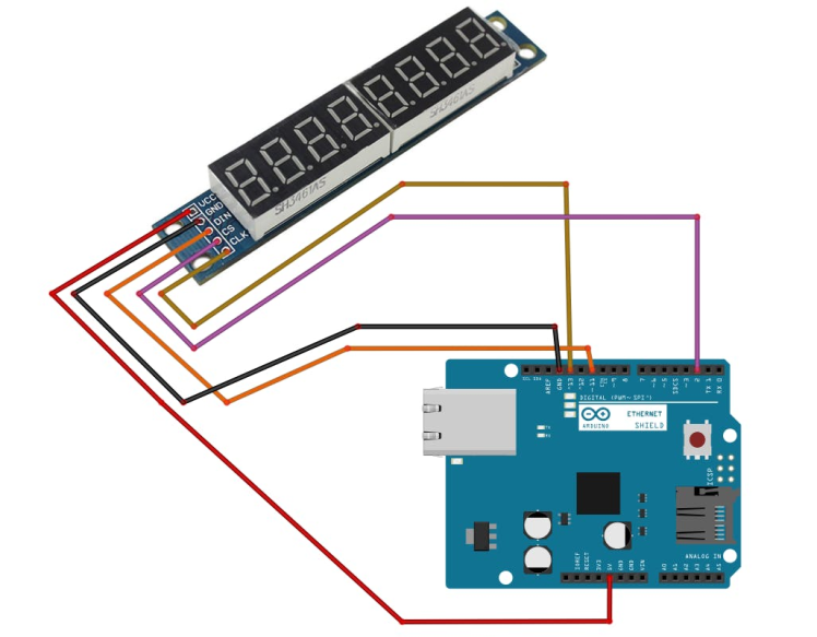
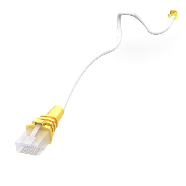
- Connect Internet LAN cable to the Arduino Ethernet Shield
- Connect LED module pin[VCC] to Arduino Ethernet Shield pin[5V]
- Connect LED module pin[GND] to Arduino Ethernet Shield pin[GND]
- Connect LED module pin[DIN] to Arduino Ethernet Shield digital pin[11]
- Connect LED module pin[CS] to Arduino Ethernet Shield digital pin[2]
- Connect LED module pin[CLK] to Arduino Ethernet Shield digital pin[13]
1 / 5
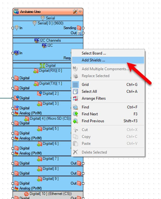
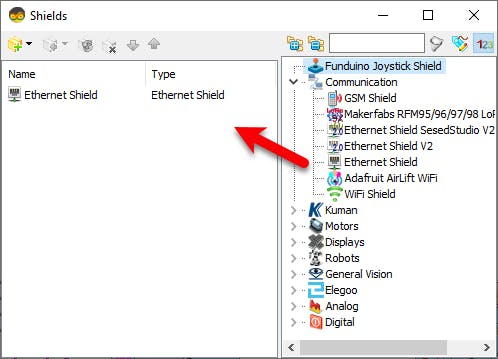
- Right mouse click on the Arduino board and select "Add Shields"
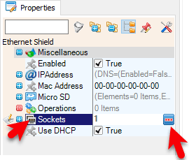
- In the "Shields" window drag "Ethernet Shield" to the left side and in the properties window select "Sockets" and click on the 3 dots button.
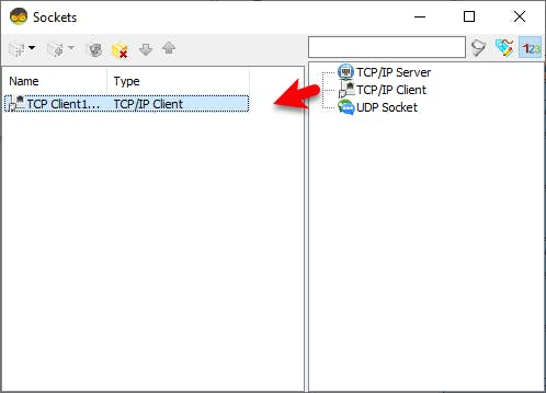
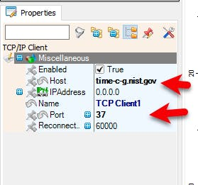
- In the "Sockets" window drag "TCP/IP Client" to the left side and in the properties window set "Port" to 37 and "Host" to: time-c-g.nist.gov
- Close the "Sockets" and "Shields" window
Note: You can find more Time servers here: https://tf.nist.gov/tf-cgi/servers.cgi
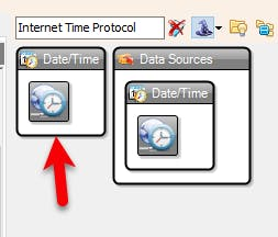
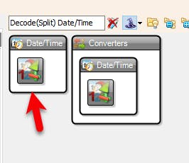
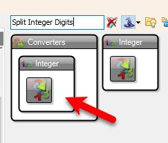
Step 4: In Visuino Add Components1 / 5
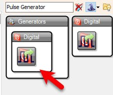
- Pulse Generator
- Internet Time Protocol
- Decode(Split) Date/Time
- 2X "Split Integer Digits
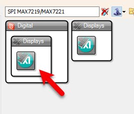
- Maxim LED Display Controller SPI MAX7219/MAX7221
1 / 7
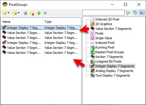


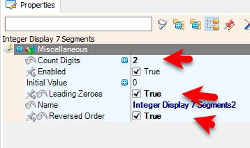
- Double click on the "LedController1" and in the "PixelGroups window" drag "Integer Display 7 Segments" to the left side and in the properties window set "Count Digits" to 2, "Leading Zeroes" to True, "Reversed Order" to True
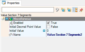
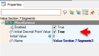
- In the "PixelGroups window" drag "Value Section 7 Segments" to the left side and in the properties window set "Initial Decmal Point Value" to True
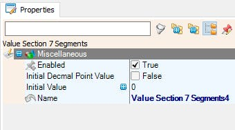
- In the "PixelGroups window" drag another "Value Section 7 Segments" to the left side
- In the "PixelGroups window" drag "Integer Display 7 Segments" to the left side and in the properties window set "Count Digits" to 2, "Leading Zeroes" to True, "Reversed Order" to True
- In the "PixelGroups window" drag "Value Section 7 Segments" to the left side and in the properties window set "Initial Decmal Point Value" to True
- In the "PixelGroups window" drag another "Value Section 7 Segments" to the left side
- Close the "PixelGroups window"
1 / 2
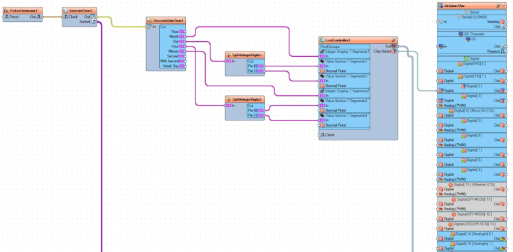
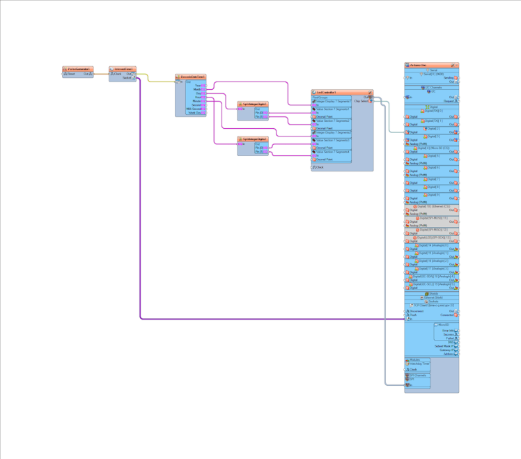
- Connect "PulseGenerator1" pin [Out] to "InternetTime1" pin [In]
- Connect "InternetTime1" pin [Socket] to "Arduino Uno" >TCP Client1 pin [In]
- Connect "InternetTime1" pin [Out] to "DecodeDateTime1" pin [In]
- Connect "DecodeDateTime1" pin [Month] to "LedController1" > "Integer Display 7 Segments1"pin [In]
- Connect "DecodeDateTime1" pin [Day] to "SplitIntegerDigits1" pin [In]
- Connect "SplitIntegerDigits1" pin[0] to "LedController1" > "Value Section 7 Segments1"pin [In]
- Connect "SplitIntegerDigits1" pin[1] to "LedController1" > "Value Section 7 Segments2"pin [In]
- Connect "DecodeDateTime1" pin [Hour] to "SplitIntegerDigits2" pin [In]
- Connect "SplitIntegerDigits2" pin[0] to "LedController1" > "Value Section 7 Segments3"pin [In]
- Connect "SplitIntegerDigits2" pin[1] to "LedController1" > "Value Section 7 Segments4"pin [In]
- Connect "DecodeDateTime1" pin [Minute] to "LedController1" > "Integer Display 7 Segments2"pin [In]
- Connect "LedController1" pin Out SPI to Arduino Pin SPI [In]
- Connect "LedController1" pin Chip Select to Arduino Digital Pin [2]
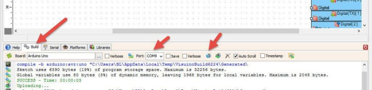
In Visuino, at the bottom click on the "Build" Tab, make sure the correct port is selected, then click on the "Compile/Build and Upload" button.
Step 8: PlayIf you power the Arduino, it will connect to the internet and the display should start showing the date and time from the NIST server.
You can also experiment with other servers that you can find here https://tf.nist.gov/tf-cgi/servers.cgi
Congratulations! You have completed your Internet Time project with Visuino. Also attached is the Visuino project, that I created for this Tutorial. You can download and open it in Visuino: https://www.visuino.eu
Schematics, diagrams and documents
Code
Credits
Related products


Leave your feedback...