


Running Faucet Alarm

Made by knaveen / Artificial intelligence / Home Automation / IoT
About the project
Detect running faucet using low powered i.MXRT1010 Development board and Edge Impulse Studio
Project info
Difficulty: Difficult
Platforms: NXP, Seeed Studio, Edge Impulse, M5Stack
Estimated time: 2 days
License: GNU General Public License, version 3 or later (GPL3+)
Items used in this project
Hardware components

Story
Overview
Poor memory are only a few of the many unpleasant experiences that accompany old age and these problems can have far-reaching implications on the comfort and security of seniors. Dementia is one of the most common neurological problems associated with the elderly. Imagine a case of seniors leaving the faucet on. The kind of water damage that might ensue is simply unimaginable. Not to mention lots of safety concerns such as electrocution and drowning. Also, sometimes kids or even adults forget to stop the faucet after use. It also adds up to your monthly water usage bills. In this project, I have built a proof of concept of an IoT enabled device which can detect running faucet using sound sensor and can alert by beeping a buzzer and optionally can send you an email.
Hardware Setup
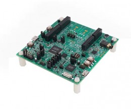
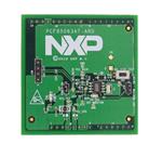
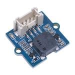
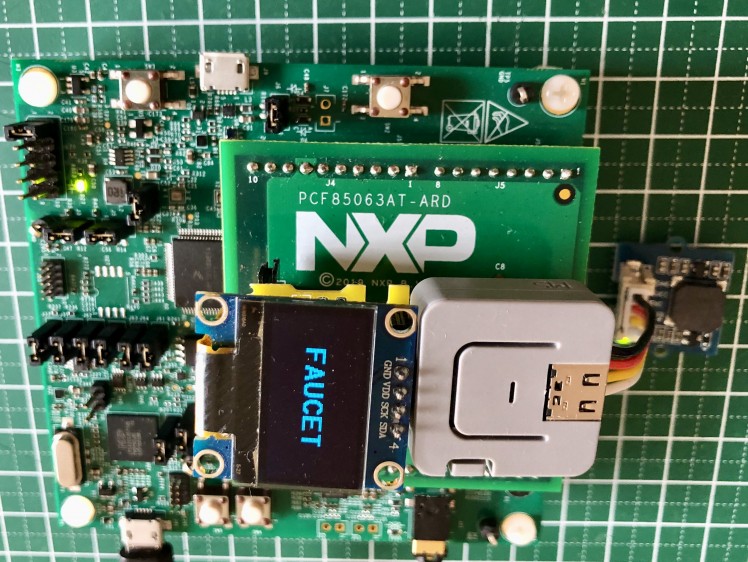
I am using i.MX RT1010 development board which has an inbuilt microphone. Also, I am using PCF85063AT-ARD Real-time clock (RTC) Shield. After mounting the PCF85063AT-ARD on the top of the i.MX RT1010 development board headers, there is no access to the other pins on the main board but the PCF85063AT-ARD has external I2C pins which can be used to connect other I2C peripherals. I am using M5Stack Atom Lite (ESP32 development board) for Wifi connectivity and SSD1306 OLED Display for displaying prediction label. Also, a Grove passive buzzer is connected to the M5Stack Atom Lite for alert.
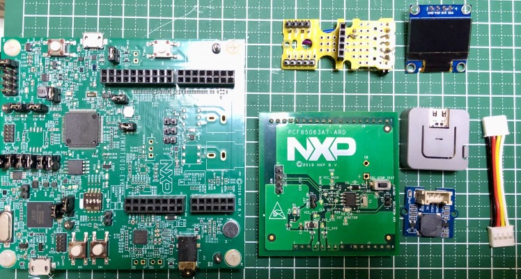
I have built a custom daughter board to mount the M5Stack Atom Lite and OLED Display to the PCF85063AT-ARD I2C headers.
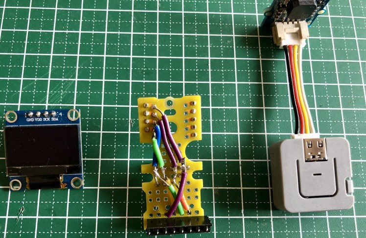
The connection diagram can be found in the Schematic section. You can see the final setup in the image (below) which is very neat and compact.
Development Environment Setup
For the development of the firmware I am using MCUXpresso Integrated Development Environment which can be downloaded from here: https://www.nxp.com/design/software/development-software/mcuxpresso-software-and-tools-/mcuxpresso-integrated-development-environment-ide:MCUXpresso-IDE.
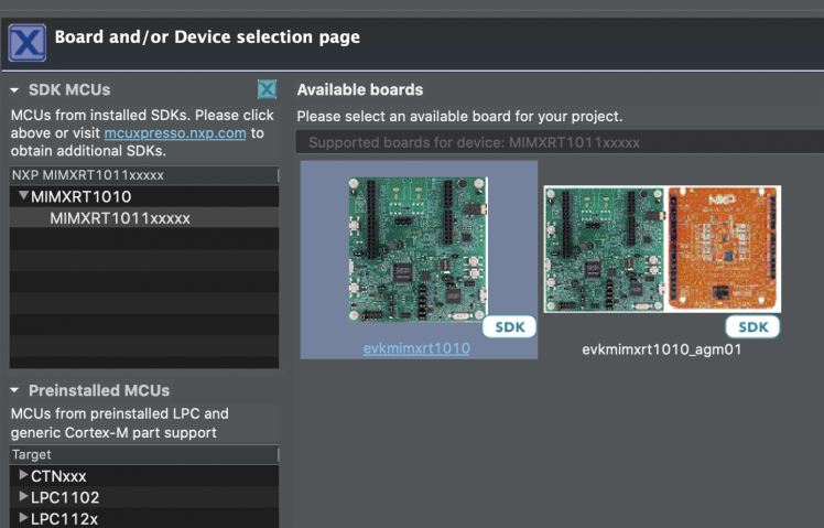
After installation open the MCUXpresso IDE and in the Quickstart Panel click at the New Project link. In the Device selection page, choose evkmimxrt1010 and click Next button.
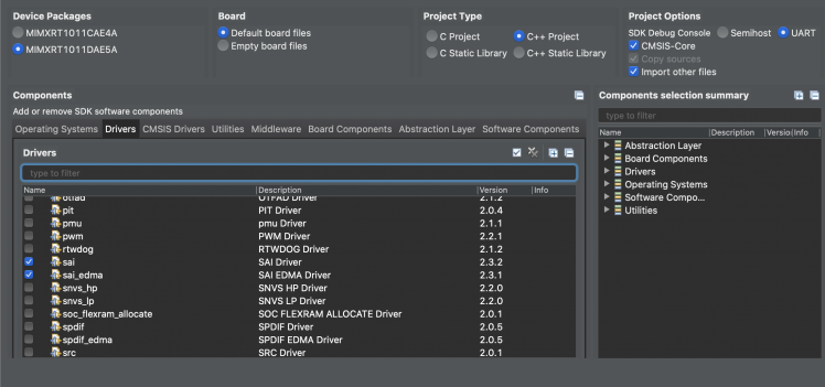
I have chosen C++ project since most of the codebase in the Tensorflow Lite and Edge Impulse SDK Library are using C++. Also, I have chosen sai-edma in the Drivers tab since we will be using Synchronous Audio Interface (SAI) for audio capture.
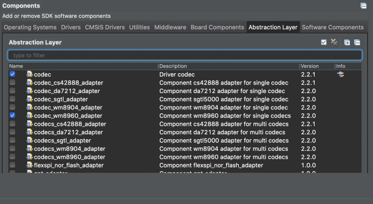
In the Components select codec_wm8960_adapter which provides audio codec control interface.
PCF85063AT-ARD RTC and SSD1306 OLED Library
Currently there is no library available for PCF85063AT-ARD RTC Shield and SSD1306 OLED in the MCUXpresso SDK so I have written one using datasheet and some help from existing codebase from Arduino library. The PCF85063AT-ARD has alarm and countdown timer functionalities other than accurate Real-time clock. We will be using countdown timer and clock functionalities in this project.
Tensorflow Lite Model creation
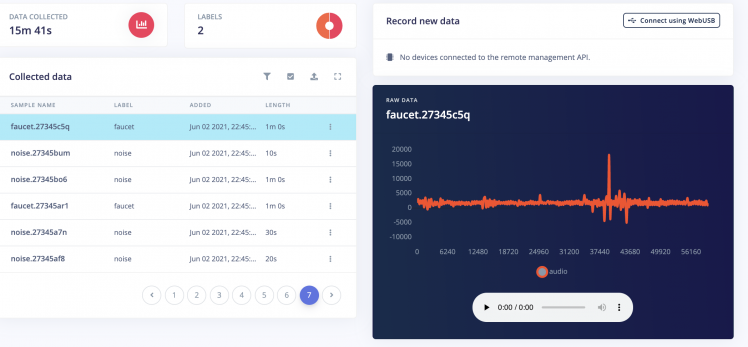
We will use Edge Impulse Studio to train and build a Tensorflow Lite model. We need to create an account first and create a new project at https://studio.edgeimpulse.com. We are using a prebuilt dataset for detecting whether a faucet is running based on audio. It contains around 15 minutes of data sampled from a microphone at 16KHz over the following two classes:
- Faucet - faucet is running, with a variety of background activity.
- Noise - just background activities.
We can import this dataset to the Edge Impulse Studio project using the Edge Impulse CLI Uploader. Please follow instruction here to install Edge Impulse CLI: https://docs.edgeimpulse.com/docs/cli-installation. The datasets can be downloaded from here: https://cdn.edgeimpulse.com/datasets/faucet.zip. After downloading the dataset, run commands below.
- $ unzip faucet.zip
- $ cd faucet
- $ edge-impulse-uploader --clean
- $ edge-impulse-uploader --category training faucet/training/*.cbor
- $ edge-impulse-uploader --category testing faucet/testing/*.cbor
You will be prompted for your username, password, and the project where you want to add the dataset. After uploading is finished we can see the data in the Data Acquisition page.
In the Impulse Design > Create Impulse page, we can add a processing block and learning block. We have chosen MFCC for processing block which extracts features from audio signals using Mel Frequency Cepstral Coefficients and for learning block we have chosen Neural Network (Keras) which learns patterns from data, and can apply these to new data for recognizing audio.

Now we need to generate feature in the Impulse Design > MFCC page. We can go with the default parameters.
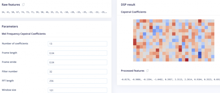
After clicking on the Save Parameters button the page will redirect to the Generate Features page where we can start generating features which would take few minutes. After feature generation we can see the output in the Feature Explorer.

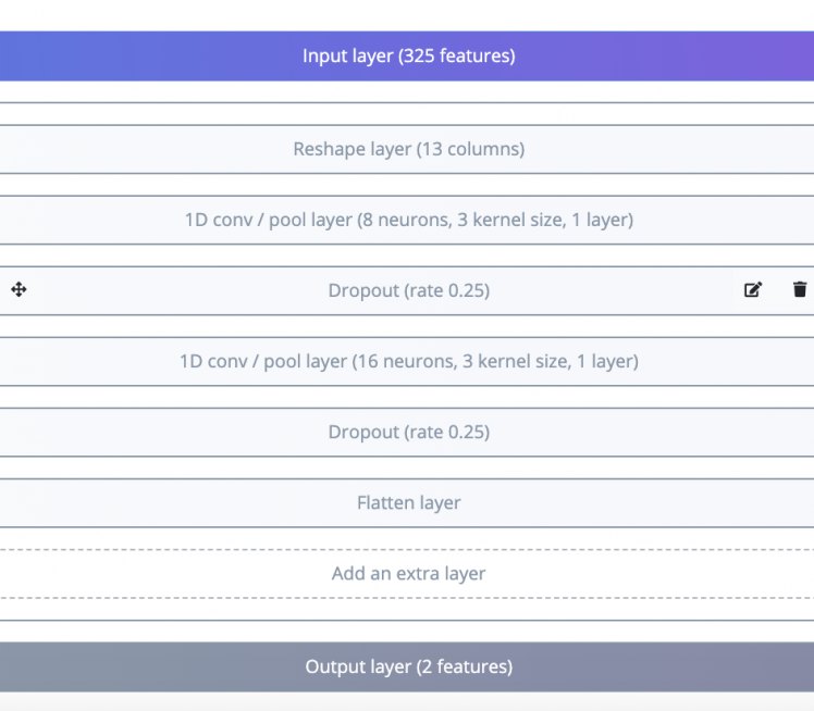
Now we can go to the Impulse Design > NN Classifier page where we can define the Neural Network architecture. We are using 1-D convolutional network which is suitable for audio classification.
After finalizing the architecture, we can start training which will take couple of minutes to finish. We can see the accuracy and confusion matrix below.
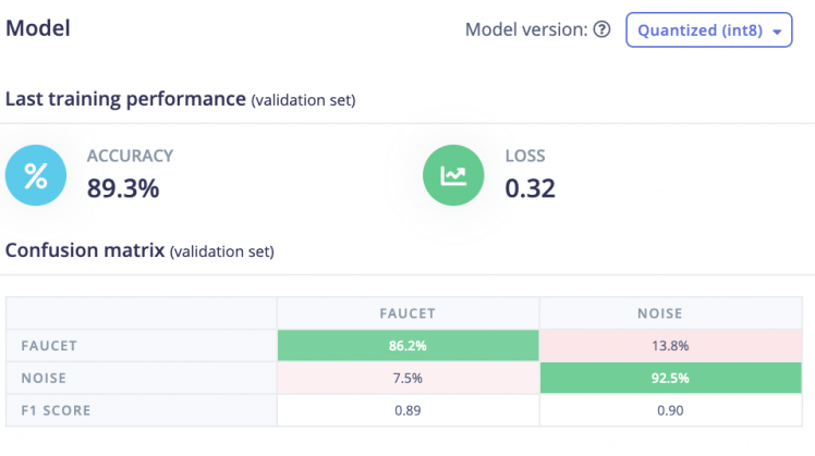
For such a small dataset 89.3% accuracy is not bad so we will be using this model. Currently, Edge Impulse Studio does not support i.MX RT1010 MCU so we need to download C++ library bundle in the Deployment page by selecting Create Library > C++ Library and click at the Build button. After building is finished, it will be downloaded at the local computer and we can unzip and move the library bundle to the MCUXpresso project source directory.
Porting the Edge Impulse Library
There is no out of the box support for the i.MX RT1010 MCU so we need to port it. In the MIMXRT1011_Faucet_Alarm_Project/source/edge-impulse-sdk/porting/ei_classifier_porting.h add following lines at the end of the file.
- #ifndef EI_PORTING_IMXRT1010
- #ifdef CPU_MIMXRT1011DAE5A
- #define EI_PORTING_IMXRT1010 1
- #else
- #define EI_PORTING_IMXRT1010 0
- #endif
We need to add two files in the porting/imxrt1010 directory.
1. porting/imxrt1010/ei_classifier_porting.cpp
- #include "../ei_classifier_porting.h"
- #if EI_PORTING_IMXRT1010 == 1
- #include <stdarg.h>
- #include <stdlib.h>
- #include <stdio.h>
- #include "clock_config.h"
- #include "board.h"
- #define EI_WEAK_FN __attribute__((weak))
- extern "C" {
- volatile uint32_t g_systickCounter;
- volatile uint32_t g_millis_counter;
- void SysTick_Handler(void)
- {
- if (g_systickCounter != 0U)
- {
- g_systickCounter--;
- }
- g_millis_counter++;
- }
- }
- void SysTick_DelayTicks(uint32_t n)
- {
- g_systickCounter = n;
- while (g_systickCounter != 0U) { }
- }
- EI_WEAK_FN EI_IMPULSE_ERROR ei_run_impulse_check_canceled() {
- return EI_IMPULSE_OK;
- }
- EI_WEAK_FN EI_IMPULSE_ERROR ei_sleep(int32_t time_ms) {
- SysTick_DelayTicks(time_ms);
- return EI_IMPULSE_OK;
- }
- uint64_t ei_read_timer_ms() {
- return (uint64_t)g_millis_counter;
- }
- uint64_t ei_read_timer_us() {
- return ei_read_timer_ms() * 1000UL;
- }
- /**
- * Printf function uses vsnprintf and output using Arduino Serial
- */
- __attribute__((weak)) void ei_printf(const char *format, ...) {
- va_list args;
- va_start(args, format);
- vprintf(format, args);
- va_end(args);
- }
- __attribute__((weak)) void ei_printf_float(float f) {
- ei_printf("%f", f);
- }
- __attribute__((weak)) void *ei_malloc(size_t size) {
- return malloc(size);
- }
- __attribute__((weak)) void *ei_calloc(size_t nitems, size_t size) {
- return calloc(nitems, size);
- }
- __attribute__((weak)) void ei_free(void *ptr) {
- free(ptr);
- }
- #if defined(__cplusplus) && EI_C_LINKAGE == 1
- extern "C"
- #endif
- __attribute__((weak)) void DebugLog(const char* s) {
- ei_printf("%s", s);
- }
- #endif // EI_PORTING_IMXRT1010 == 1
2. porting/imxrt1010/debug_log.cpp
- #include "../ei_classifier_porting.h"
- #if EI_PORTING_IMXRT1010 == 1
- #include "tensorflow/lite/micro/debug_log.h"
- #include <stdio.h>
- #include <stdarg.h>
- // On IMXRT1010, we set up a serial port and write to it for debug logging.
- #if defined(__cplusplus) && EI_C_LINKAGE == 1
- extern "C"
- #endif // defined(__cplusplus) && EI_C_LINKAGE == 1
- void DebugLog(const char* s) {
- ei_printf("%s", s);
- }
- #endif // EI_PORTING_IMXRT1010
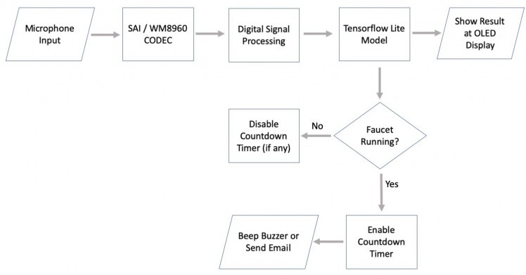
Flowchart diagram
The high level application flowchart diagram is given below.
Using i.MX RT1010 FlexRAM
The i.MXRT1010 has limited 128 KB memory divided into 32KB banks. The compilation gets failed due to overflow of the memory. Since we are using double buffering to capture audio data; first buffer for the audio sampling process, filling the buffer with new sample data and second buffer for the inference process, get sample data out the buffer, extract the features and run inference. So it requires more memory. If we build the firmware it displays the error below.
Error: arm-none-eabi/bin/ld: MIMXRT1011_Faucet_Alarm_Project.axf section `.bss' will not fit in region `SRAM_DTC'.
- Memory region Used Size Region Size %age Used
- BOARD_FLASH: 289968 B 16 MB 1.73%
- SRAM_DTC: 49840 B 32 KB 152.10%
- SRAM_ITC: 0 B 32 KB 0.00%
- SRAM_OC: 0 B 32 KB 0.00%
- NCACHE_REGION: 0 B 32 KB 0.00%
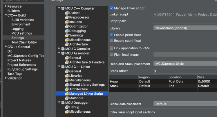
Thanks to the FlexRAM, we can reconfigure the SRAM_DTC to increase heap memory size by following steps. In the Quickstart panel, click at Edit project setting. In the setting window, select C/C++ build > Settings > MCU C++ Linker > Managed Linker Script and in the size field change the default heap value which is 2 KB (0x800) to 20 KB (0x5000). Click Apply and Save button to save the settings.
Also, in the main code modify the declaration of the buffer variables which are taking large memory by prefixing __DATA(RAM3) so that the data will be placed in the OCRAM memory region.
- __DATA(RAM3) static inference_t inference;
- __DATA(RAM3) static signed short sampleBuffer[EI_CLASSIFIER_SLICE_SIZE>>1];
After rebuilding the project we can see in the output that all memory regions are within their limits.
- Memory region Used Size Region Size %age Used
- BOARD_FLASH: 309988 B 16 MB 1.85%
- SRAM_DTC: 28268 B 32 KB 86.27%
- SRAM_ITC: 0 B 32 KB 0.00%
- SRAM_OC: 20012 B 32 KB 61.07%
- NCACHE_REGION: 0 B 32 KB 0.00%
Pin Configuration
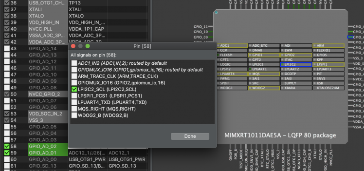
The WM8960 Codec IC is using LPI2C1. For the PCF85063AT-ARD we will configure LPI2C2 (SCL/SDA) on the GPIO_AD_01 and GPIO_AD_02 which are the pins on the headers connected to the PCF85063AT IC over I2C. Also, OLED display and ESP32 I2C slaves will be connected over this LPI2C2 bus. In the Quickstart Panel > MCUExpresso Config Tools >> Open Pins, we can configure the pins.
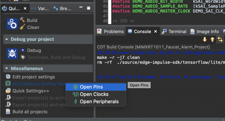
Click on the GPIO_AD_01 and GPIO_AD_02 one by one and assign LPI2C2_SCL and LPI2C2_SCL. After that choose ConfigTools > Update Code from the top menu to generate the code.
The generated code are saved in the board/pin_mux.c file which is not correct and did not work. So after getting the help from the NXP forum we needed to modify the generated code as shown below.
- void BOARD_InitPins(void)
- {
- CLOCK_EnableClock(kCLOCK_Iomuxc);
- IOMUXC_SetPinMux(IOMUXC_GPIO_AD_01_LPI2C2_SDA, 1U);
- IOMUXC_SetPinMux(IOMUXC_GPIO_AD_02_LPI2C2_SCL, 1U);
- IOMUXC_SetPinConfig(IOMUXC_GPIO_AD_02_LPI2C2_SCL, 0xD8B0U);
- IOMUXC_SetPinConfig(IOMUXC_GPIO_AD_01_LPI2C2_SDA, 0xD8B0U);
- }
Build i.MXRT1010 firmware
Clone the project repository.
- $ cd ~
- $ git clone https://github.com/metanav/MIMXRT1011_Faucet_Alarm.git
Open project in the MCUXpresso IDE. In the Quickstart panel click at the Build link. After building is finished, click on Quickstart panel > Debug to flash and run the project in debugging mode.
Build ESP32 firmware
We also need to build ESP32 firmware and flash to M5Stack Atom Lite to provide Wifi and buzzer functionality. Please follow the instructions (link below) to install the ESP IDF toolchain for building and flashing the firmware: https://docs.espressif.com/projects/esp-idf/en/latest/esp32/get-started.
- $ cd ~/MIMXRT1011_Faucet_Alarm/esp32_i2c_slave_ntp_smtp
- $ idf.py build
- $ idf.py -b 1500000 -p /dev/tty.usbserial-5D52E80CAC flash
Please change the usb serial device path above according to your OS. The ESP32 firmware runs a FreeRTOS application which acts as an I2C slave at address 0x19. The main application in the MCUExpresso project connects to this I2C Slave to get NTP time to set PCF85063AT RTC at startup, enable/disable buzzer and send email alert message.
On-device inferencing
The audio is captured using Synchronous Audio Interface (SAI) with Enhanced Direct Memory Access (eDMA) controller. The audio MFCC blocks in the DSP application (part of Edge Impulse Library) extracts coefficients from the audio signal and sends to the model as an input. The model predicts the audio as a Faucet or Noise and output is displayed at the OLED screen. For the demo purpose, we have kept the Faucet running alarm threshold at 25 continuous Faucet running detection after crossing that it will trigger the buzzer by sending message to ESP32 over I2C and start the countdown timer using the PCF85063AT-ARD for next 10 seconds. Once the countd
Schematics, diagrams and documents
Code
Credits
Related products


Leave your feedback...