
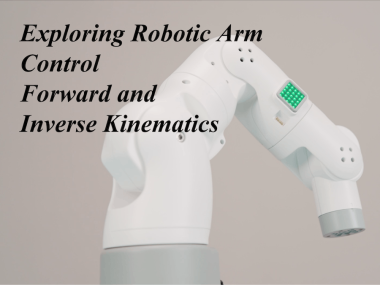
Exploring Robot Arm Control: Forward And Inverse Kinematics
Made by Elephant Robotics / Robotics
About the project
In this article, we mainly introduce the forward and inverse kinematics of the robotic arm and how to apply it to the 7-axis robot arm myArm
Project info
Difficulty: Moderate
Platforms: Raspberry Pi, ROS, Elephant Robotics
Estimated time: 1 hour
License: GNU General Public License, version 3 or later (GPL3+)
Items used in this project

Story
In this article, we will delve into two core concepts of robotics: forward kinematics and inverse kinematics. These two concepts form the basis for understanding and controlling the movement of robotic arms. Through a specific example of a 7-axis robotic arm, we will detail how to compute the forward and inverse kinematics of the robotic arm. We will first explain the basic concepts and mathematical principles of forward and inverse kinematics, and then we will demonstrate how to apply these principles to calculate the movement of a 7-axis robotic arm. Our goal is to provide readers with a deep understanding of robotic arm motion control and how to apply this knowledge in practice.
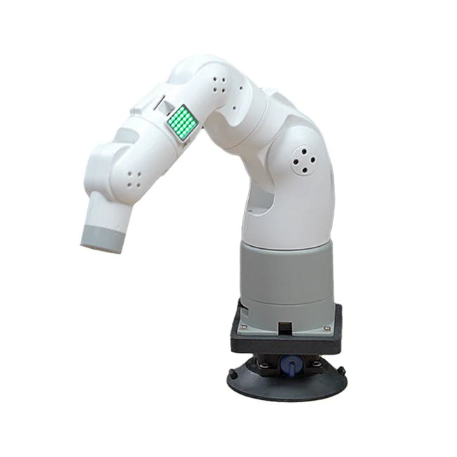
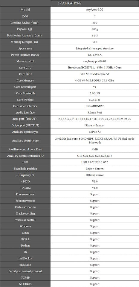
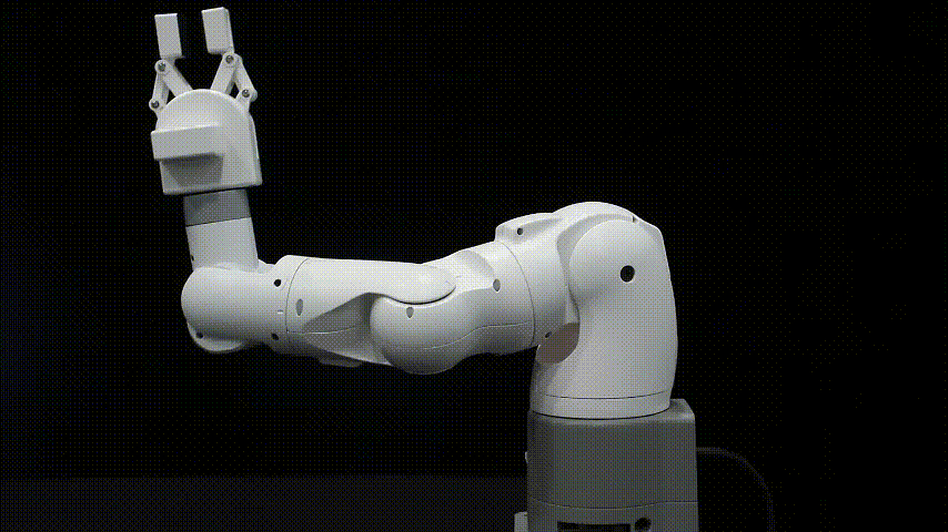
myArm 300 PiThe myArm 300 Pi is an innovative collaborative robotic arm with a symmetrical configuration, boasting 7 DOF. Its design style continues the compact and lightweight features of the myCobot series. Equipped with 7 high-precision servo motors, the myArm has a maximum working radius of 300mm and a maximum payload capacity of 200g at the end effector.Its impressive repeatability ensures a positioning accuracy of up to ±0.5mm, guaranteeing precise and reliable performance.
The control board of the myArm 300 Pi adopts the Raspberry Pi 4B 4G, which is a widely recognized mini-computer renowned for its exceptional performance and versatile programming environment. This means users can control the myArm 300 Pi using various programming languages, including Python, C++, Java, etc., greatly enhancing user convenience and flexibility. Additionally, the myArm 300 Pi support ROS1/ROS2, offering a multitude of functionalities within the ROS operating system, including path planning, obstacle avoidance, 3D perception, and various other capabilities to further augment its overall performance.
If we want to control a robotic arm, we need a set of algorithms for the motion control of the robotic arm. Forward and inverse kinematics are important components of this. Before introducing forward and inverse kinematics, we would like to first introduce the DH model, which makes the calculation of forward and inverse kinematics more direct and simple.
DH ModelThe DH parameter model is a commonly used method in robotics to describe robot kinematics. It describes the robot's joint links through a set of parameters, thus conveniently calculating the position and posture of the robot's end effector.
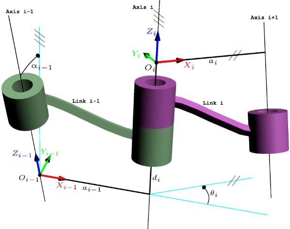
When using the DH model to describe a robotic arm, we decompose the robotic arm into a series of links and joints, each of which is associated with a coordinate system. We choose a reference coordinate system, usually the base (pedestal) coordinate system of the robotic arm. Then, we define a coordinate system for each link and joint. We define two coordinate systems: the coordinate system of the previous link and the current link. The transformation between these two coordinate systems is described by four parameters:
● Link length (a): It represents the distance between adjacent links, measured along the normal of the previous link. It usually refers to the length of the link or the length of the link axis.
● Link rotation angle (α): It represents the rotation angle between adjacent links, rotating around the normal of the previous link. It usually refers to the rotation between link axes.
● Joint length (d): It represents the length of the link or the joint, measured along the normal of the current link. It usually refers to the length of the joint axis.
● Joint rotation angle (θ): It represents the rotation angle of the joint, rotating around the normal of the current link. It usually refers to the angle of the joint or the rotation of the joint.
By combining these parameters, a four-dimensional transformation matrix can be constructed, which can represent the position and posture of the robotic arm's end effector.
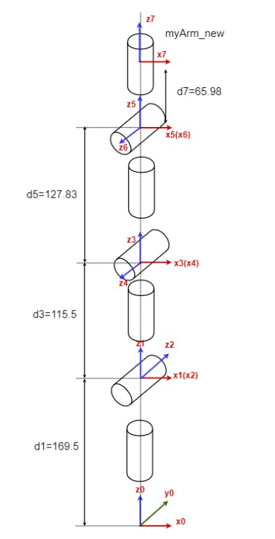
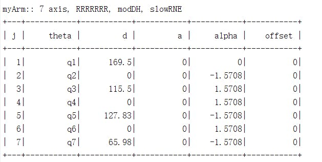
Taking myArm as an example, the following figure shows the DH model diagram and SDH parameter table of myArm 300. What can we do with a DH model diagram of a robotic arm?
● Forward kinematics: By giving joint angles, the DH model diagram can be used to calculate the position and posture of the robotic arm's end effector, thereby enabling path planning and motion control.
● Inverse kinematics: Conversely, the DH model diagram can also be used to solve inverse kinematics problems, i.e., given the target position and posture, calculate the changes in joint angles to achieve a smooth motion trajectory.
● Path planning: Given a starting position and an ending position, the DH model can be used to plan the motion path of the robotic arm. This may involve solving a series of inverse kinematics problems.
1 / 2
Forward kinematics is a method to calculate the position and orientation of the end effector of a robotic arm from the base. Given the angles of each joint, we can calculate the position and orientation of the end of the robotic arm. This is a process based on geometry and trigonometry.
Here's a simple example: in a plane coordinate system, knowing the lengths of the links l1 and l2, and the rotation angles of the two joints θ1 and θ2, we can calculate the position (x, y) of the end effector using trigonometric functions.
x = l1cos(θ1) + l2cos(θ1+θ2)
y = l1sin(θ1) + l2sin(θ1+θ2)
This gives us the coordinates of x and y.

In practical applications, we usually calculate directly in three-dimensional space. We can use homogeneous coordinates for the transformation. In homogeneous coordinates, a two-dimensional point (x, y) can be represented as a three-dimensional point (x, y, 1), and a three-dimensional point (x, y, z) can be represented as a four-dimensional point (x, y, z, 1). In this way, we can use the same matrix multiplication operation to describe translation and rotation.
For example, a two-dimensional translation transformation can be represented as a 3x3 matrix of the following form:
[[1, 0, dx],
[0, 1, dy],
[0, 0, 1]]
Where dx and dy represent the translation distance in the x and y-axis directions. Similarly, a two-dimensional rotation transformation can be represented as a 3x3 matrix of the following form:
[[cos(theta), -sin(theta), 0],
[sin(theta), cos(theta), 0],
[0, 0, 1]]
Where theta represents the rotation angle, which is θ in the DH parameters.
By multiplying all the transformation matrices of the joints, we can get the total transformation from the robot base to the end effector. This is the basic calculation process of forward kinematics. This process can be represented in the following mathematical form:
T = A1 * A2 * A3 * ... * AnWhere T is the total transformation matrix, Ai is the transformation matrix of the i-th joint, and n is the number of joints. Note that matrix multiplication does not satisfy the commutative law, so the order of multiplication is important. The final total transformation matrix T calculates the coordinates of the end of the robotic arm relative to the base. Understanding the DH model in advance is very helpful for understanding the matrix transformation later.
Inverse KinematicsInverse kinematics is the process of calculating the angles of each joint of a robotic arm based on the position and posture of the end effector. It's the opposite of forward kinematics, where we determine the angles of each joint. The calculation of inverse kinematics is usually much more complex than that of forward kinematics. It's a process of inferring causes from effects, usually involving the solution of nonlinear equations, and the solution may not be unique, or may not exist at all. Let's illustrate with the example of a 2-degree-of-freedom planar robotic arm. We know the values of (x, y) and want to find the angles θ1 and θ2.
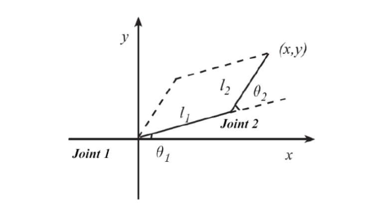
First, we can calculate the distance d from (x, y) to the origin. This can be obtained using the Pythagorean theorem (sqrt represents the square root):
d = sqrt(x^2 + y^2)Then, we can use the cosine theorem to solve for the angle θ2 of the second joint. The cosine theorem can describe the cosine value of any angle in a triangle with known side lengths. Here, we can consider d, L1, and L2 as the three side lengths, and then solve for θ2:
cos(theta2) = (L1^2 + L2^2 - d^2) / (2 * L1 * L2)Because θ2 may have two solutions (clockwise and counterclockwise), we need to choose the appropriate solution based on the actual situation.
Finally, we can use the sine theorem or the cosine theorem to solve for the angle θ1 of the first joint. The sine theorem can describe the relationship between the sine values of three side lengths and their corresponding angles. Here, we can consider d, L1, and θ1 as the three known values, and then solve for θ1:
theta1 = atan2(y, x) - atan2(L2 * sin(theta2), L1 + L2 * cos(theta2))After solving, we can know the angles of each joint. This is the solution method in two-dimensional space. The calculation method in three-dimensional space is the same. When calculating, we need to consider the constraints of the robotic arm joints and other factors to determine the final angle.
7-axis Robotic Arm ExampleNext, python will be used to program myArm, using the pymycobot library.
Joint ControlForward kinematics algorithms usually have a definite result. The goal of forward kinematics is to calculate the position and posture of the robotic arm actuator based on the given joint angles, and there is only one unique result. Below is the code using angle control:
from pymycobot import Myarm
import time

# create myarm object
ma = Myarm('/dev/ttyAMA0',115200)
ma.send_angles([degree_list],speed)

# send_angles function
def send_angles(self, degrees, speed):
        """Send the degrees of all joints to robot arm.

        Args:
            degrees: a list of degree values(List[float]).n
                        for mycobot: [0.0, 0.0, 0.0, 0.0, 0.0, 0.0].n
                        for mypalletizer: [0.0, 0.0, 0.0, 0.0]
                        for mypalletizer 340: [0.0, 0.0, 0.0]
                        for myArm: [0.0, 0.0, 0.0, 0.0, 0.0, 0.0, 0.0].n
            speed : (int) 1 ~ 100
        """
        # self.calibration_parameters(degrees=degrees, speed=speed)
        degrees = [self._angle2int(degree) for degree in degrees]
        return self._mesg(ProtocolCode.SEND_ANGLES, degrees, speed)
As mentioned earlier, inverse kinematics algorithms are relatively complex and may have multiple solutions or no solution at all. The control of inverse kinematics algorithms is achieved by controlling the changes in the coordinates of the end of the robotic arm, allowing the robotic arm to move to the next coordinate position. Here is the code for controlling coordinate movement written in Python:
from pymycobot import Myarm
import time

# create myarm object
ma = Myarm('/dev/ttyAMA0',115200)
ma.send_coords([coordinates_list],speed,mode)
# mode: 0:linear motion,1:nonlinear motion

 def send_coords(self, coords, speed, mode=None):
        """Send all coords to robot arm.

        Args:
            coords: a list of coords value(List[float]).
                        for mycobot :[x(mm), y, z, rx(angle), ry, rz]n
                        for mypalletizer: [x, y, z, θ]
                        for mypalletizer 340: [x, y, z]
            speed : (int) 0 ~ 100
            mode : (int) 0 - angluar, 1 - linear (mypalletizer 340 does not require this parameter)
        """
        # self.calibration_parameters(coords=coords, speed=speed)
        coord_list = []
        for idx in range(3):
            coord_list.append(self._coord2int(coords[idx]))
        for angle in coords[3:]:
            coord_list.append(self._angle2int(angle))
        # print(coord_list)
        if mode is not None:
            return self._mesg(ProtocolCode.SEND_COORDS, coord_list, speed, mode)
        else:
            return self._mesg(ProtocolCode.SEND_COORDS, coord_list, speed)
A 7-axis robotic arm is also known as a redundant robot. The extra axis is usually used to provide more flexibility and degrees of freedom, leading to a phenomenon where there are many different postures when the end coordinate value of the robotic arm remains unchanged.
This is a feature of inverse kinematics mentioned at the beginning: there are many different solutions under the same coordinates. Another key piece of information in coordinate control is the type of motion path of the end of the robotic arm, which can be linear or non-linear.
● Linear motion: In this mode, the end effector of the robot moves in a straight line between two points. This means that no matter how the joints of the robot move, the end effector will move along a straight path from one point to another. This type of motion is typically used in applications that require precise position control, such as assembly tasks on an assembly line.
● Non-linear motion: In this mode, the path of the robot's end effector is not a straight line, but a curve. This type of motion allows the robot to move more flexibly in complex environments, such as situations where it needs to avoid obstacles or move along a specific path.
SummaryAfter exploring the basic concepts and mathematical principles of forward and inverse kinematics, we can see that these two concepts are particularly important in the control of robotic arms. However, forward and inverse kinematics are just a part of the control of robotic arms. In practical applications, we also need to consider dynamics, control theory, sensor feedback, and the limitations of actual hardware.
With the advancement of technology, robotic arms will play an increasingly important role in many fields, including manufacturing, healthcare, home services, search and rescue, and more. By deeply understanding these knowledge, we can better understand what a robotic arm is and allow it to play a greater role in various applications.
If you like this article, feel free to leave a comment or like below. Your support is our motivation to update!
Credits
Elephant Robotics
Elephant Robotics is a technology firm specializing in the design and production of robotics, development and applications of operating system and intelligent manufacturing services in industry, commerce, education, scientific research, home and etc.
Related products


Leave your feedback...