





Esp32 Touchscreen Home Automation Control Panel - Esphome

Made by rau7han / Home Automation / IoT
About the project
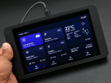
In this tutorial, we will learn how to make a wall-mounted Smart Home Dashboard by using two ESP32 boards
Project info
Difficulty: Moderate
Platforms: Espressif
Estimated time: 1 day
License: Creative Commons Attribution-NonCommercial CC BY-NC version 4.0 or later (CC BY-NC 4+)
Items used in this project
Hardware components


Story
In this tutorial, we will learn how to make a wall-mounted Smart Home Dashboard by using two ESP32 boards. The first one is a VIEWE ESP32-S3 board with a built-in 7-inch 800x480 touchscreen, which runs the user interface.
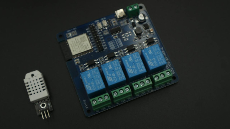
The second one is a ready-made ESP32 4-channel relay board, which switches the four relays and reads a DHT22 temperature and humidity sensor. Both the boards communicate with each other wirelessly by using the ESP-NOW protocol.
The dashboard also fetches live weather data from the OpenWeatherAPI, the UV index from the Open-Meteo API, and the time from an NTP server.
It has four pages - Home, Weather, History and Settings - and all the user settings are stored in the ESP32 flash memory, so they are not lost after a power failure.
Supplies1 / 9
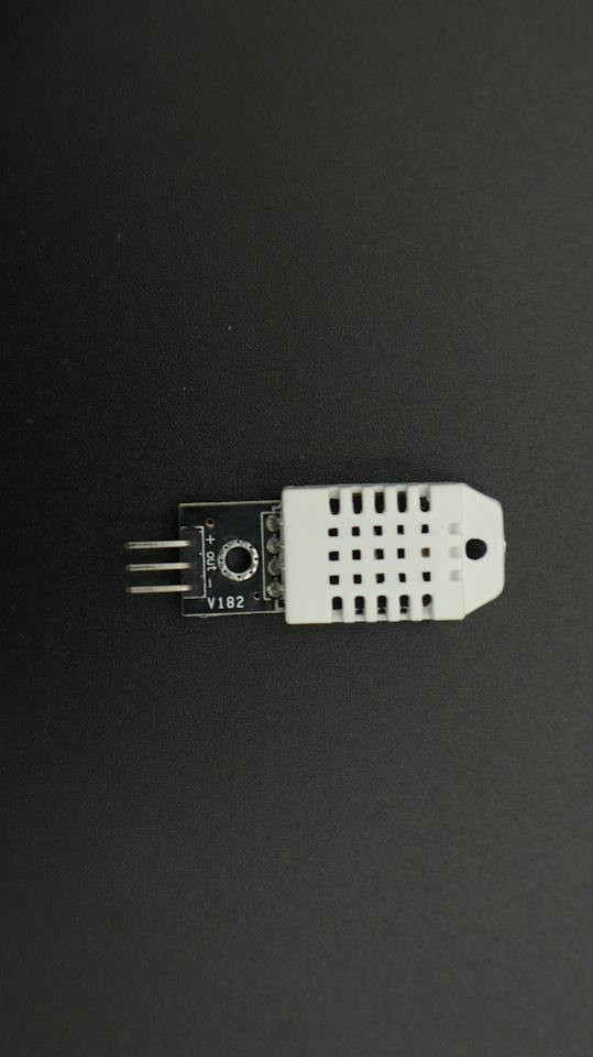
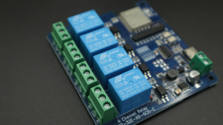
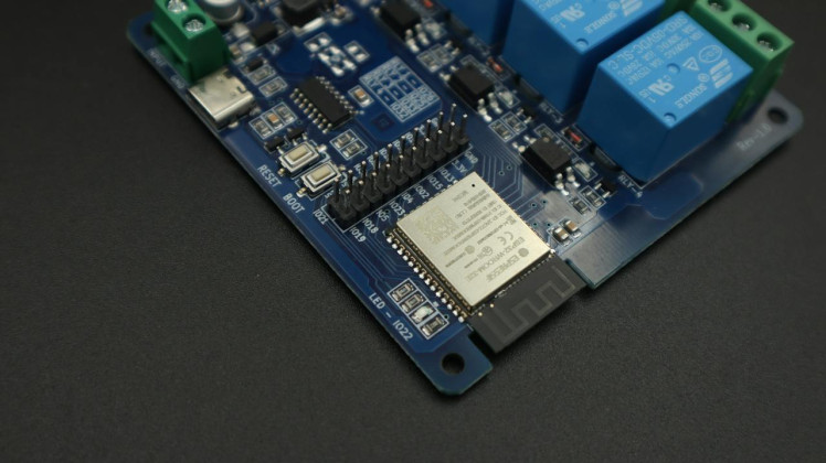
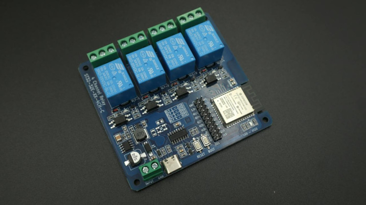
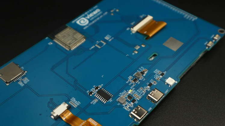
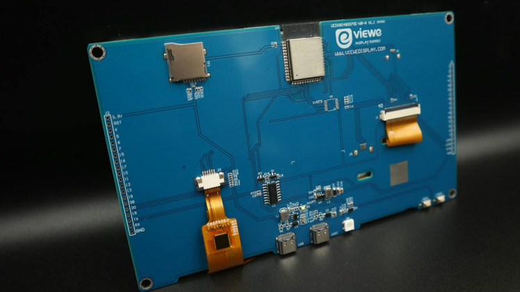
The following components are required to make this project:
- VIEWE ESP32-S3 Display Board - 7 inch (Viewe_Display)
- ESP32 4-Channel Relay Board
- DHT22 Temperature and Humidity Sensor
- Jumper Wires
- USB Cables
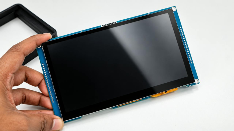
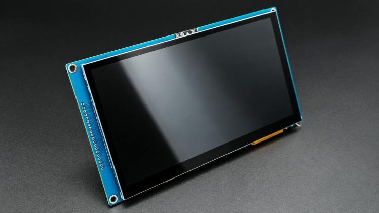
This is the main controller and touchscreen used for the dashboard. It combines an ESP32-S3, a 7-inch 800×480 TFT display, and a multi-touch capacitive touchscreen on a single board from viewedisplay.
Main specifications:
- ESP32-S3-N16R8, up to 240 MHz
- 7-inch 800×480 TFT display
- 8 MB PSRAM
- 16 MB Flash
- 2.4 GHz Wi-Fi and Bluetooth 5
- Multi-point capacitive touch
- Supports Arduino, ESP-IDF and LVGL
- USB/UART connectivity
The 8 MB PSRAM is especially useful for this project because the large 800×480 LVGL interface requires much more memory than a basic ESP32 display.
For this project, the board runs the complete touchscreen dashboard, weather interface, relay controls, ESP-NOW communication, history and settings pages.
Working Principle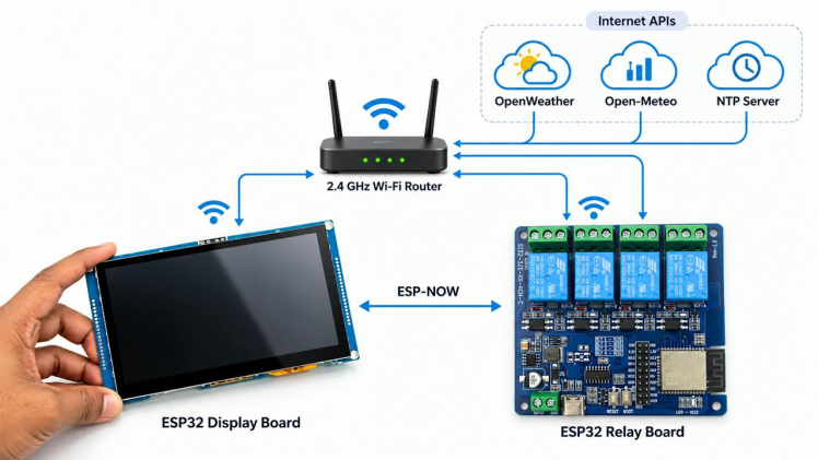
Both the ESP32 boards connect to the same 2.4 GHz WiFi router. The display board gets the weather and the forecast from OpenWeather, the UV index fromOpen-Meteo, and the time from an NTP server.
When you tap a relay button, the display sends an ESP-NOW command to the relay board. The
relay board checks the sender MAC address, switches the requested relay, and sends the
actual relay states and the DHT22 readings back to the display. The display then updates the relay button to ON or OFF and adds the change to the History
page.
The relay board sends its status every 2 seconds, and the display also requests the
status every 5 seconds. If no status is received for 15 seconds, the relay board is shown
as offline.
Step 2: Schematic1 / 2
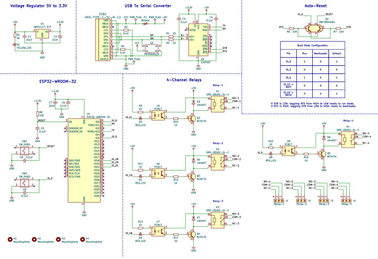
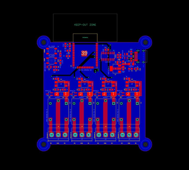
The display board does not require any external wiring, because the LCD, the touch controller and the backlight are already connected internally. So the schematic covers only the relay node.
The connections are as follows:
DHT22 Sensor to ESP32
- VCC --- 3.3V
- OUT --- GPIO 13
- GND --- GND
4-Channel Relay Module to ESP32
- IN1 --- GPIO 26
- IN2 --- GPIO 25
- IN3 --- GPIO 33
- IN4 --- GPIO 32
- GND --- GND
- VCC --- as per your module datasheet
1 / 2
I have also attached the schematic and Gerber files for the ESP32 4-channel relay board. If you want to make your own version, you can send the Gerber files to NextPCB for PCB manufacturing.
NextPCB provides PCB fabrication and assembly services for prototypes as well as small production runs.
Before ordering, you can also use HQDFM, NextPCB's free Gerber viewer and DFM analysis tool. It can help you check the PCB layers and find possible manufacturing issues before sending the board for production.
If you are planning to manufacture your own PCB, you can check the latest PCB and PCBA offers directly on the NextPCB website.
Step 4: 3D Printed Enclosure and AssemblyFor the display unit, I also made a simple 2-part 3D printed enclosure so the dashboard looks clean and can be mounted on the wall easily.
1 / 8
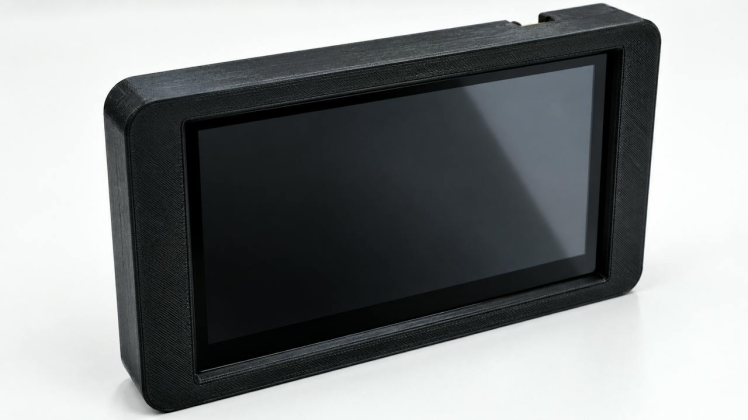
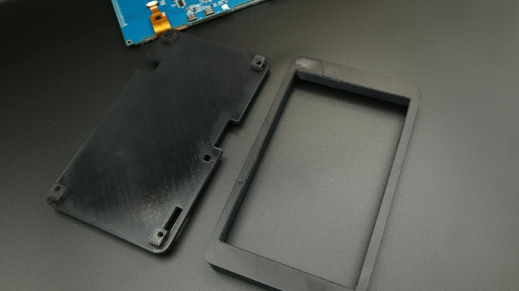
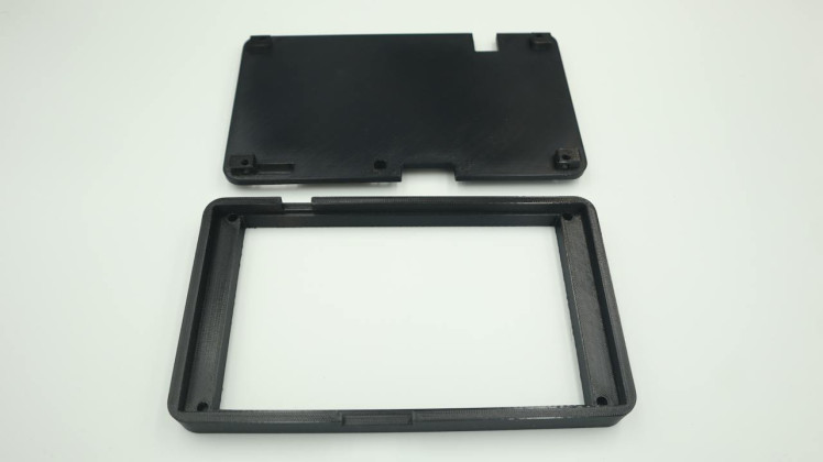
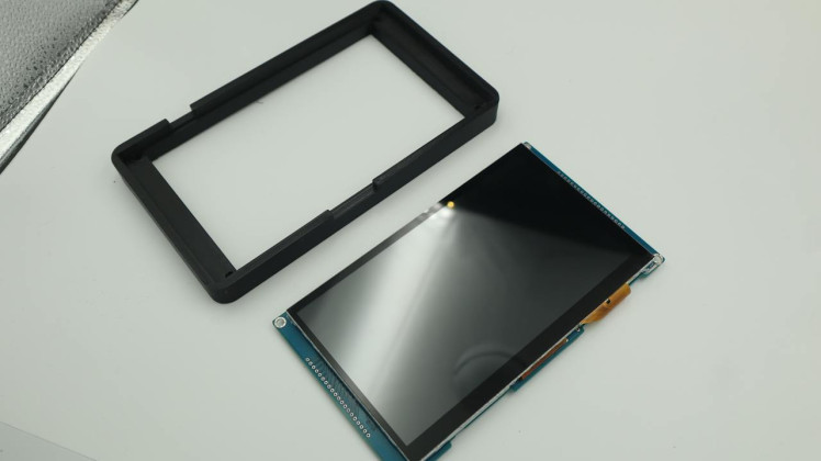
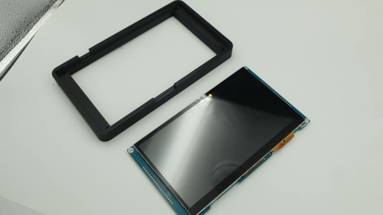
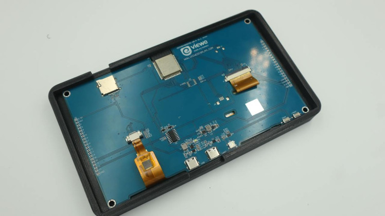
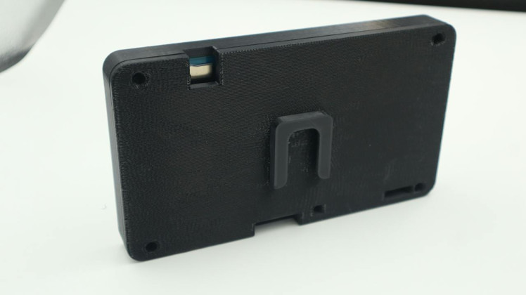
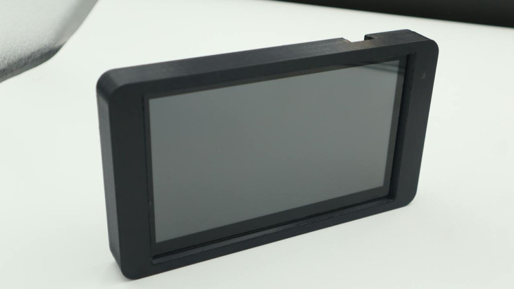
The enclosure has:
- a front frame for the display
- a back cover
- a small wall hook / mounting support on the back side
The display board fits inside the front part, and the back cover closes it from behind with screws.
I also kept cutouts for the USB ports and other required openings, so the board can still be powered and programmed easily without removing it again.
First, place the display board inside the front frame and make sure the screen sits properly in the opening.
After that, align the back cover and fix it in place.
Once assembled, the enclosure gives the display a much better finish and also makes it easy to use as a wall-mounted smart panel.
If you want, you can print the enclosure in black PLA like I did, but any material will work.
You can also attach the STL files in this step so anyone can directly print the case.
Step 5: Understanding the ESP-NOW CommunicationESP-NOW is a wireless protocol from Espressif that lets ESP32 boards communicate directly using their MAC addresses, without needing a router or IP address.
1 / 3
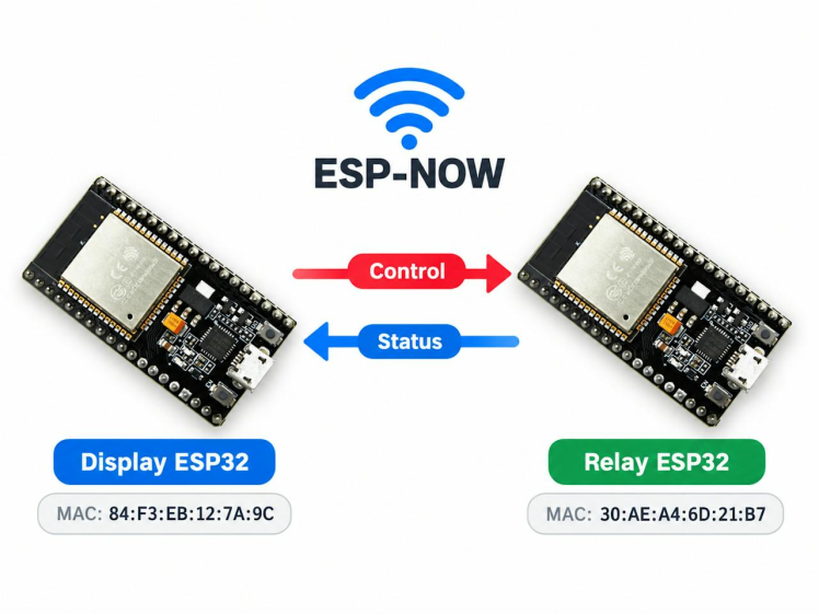
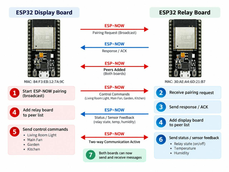
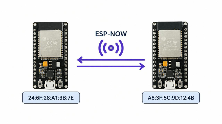
In this project, both boards use a shared espnow_protocol.h file for four message types:
- Relay Command: switch one relay
- Scene Command: control all four relays
- Status Request: ask for current status
- Relay + Sensor Status: send confirmed relay states and DHT22 readings back to the display
The relay sends status every 2 s, the display requests status every 5 s, pending commands timeout after 2.5 s, and the relay is marked offline after 15 s without a response.
Step 6: Getting the Weather Data1 / 6
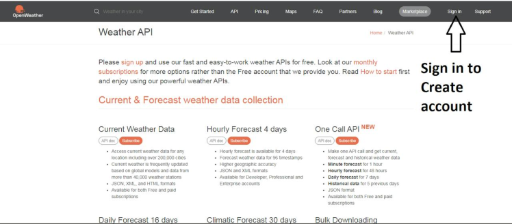
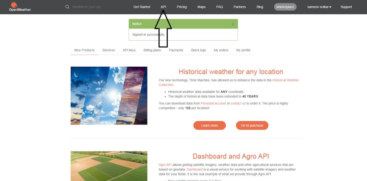
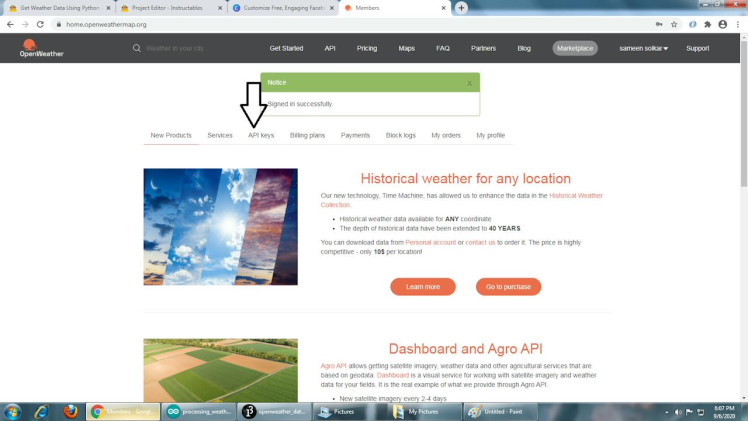
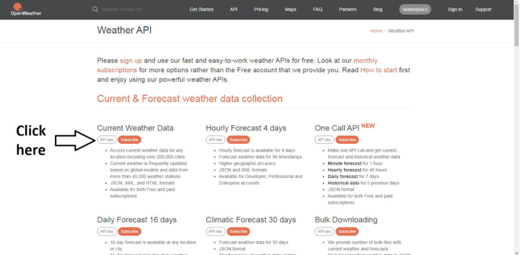
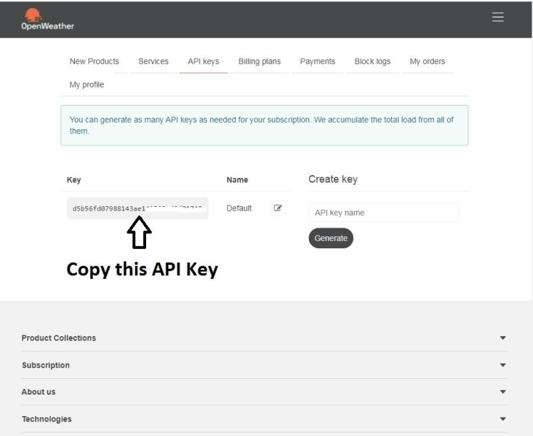
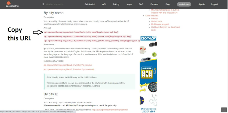
The dashboard collects the weather information from two different free APIs.
OpenWeather API
First, create a free account on the OpenWeatherwebsite and generate an API key. Please
note that the free API key does not include the One Call 3.0 API. If we try to use the
One Call 3.0 endpoint with a free key, the server returns an HTTP 401 error. I have faced
this problem myself during the development.
So in this project I have used the two free 2.5 endpoints instead:
The first one gives the present weather condition, temperature, feels-like temperature,
humidity, pressure, visibility, cloud cover, wind speed, wind direction, rainfall,
sunrise and sunset. The second one is the 5-day forecast with a 3-hour interval, from
which the code prepares the 24-hour temperature chart as well as the 5-day forecast
display.
Open-Meteo API
The free OpenWeather endpoints do not provide the UV index. So the UV value is collected
separately from theOpen-Mateo Air Quality API:
http://air-quality-api.open-meteo.com/v1/air-quality
This API does not require any key at all. If this request fails for any reason, the remaining weather data is still displayed normally and only the UV field shows.
The weather data is refreshed once in every 10 minutes. If a request fails, it is retried after 60 seconds. The first request is sent about 3 seconds after the WiFi is connected.
Step 7: Wi-Fi and API ConfigurationDo not store your Wi-Fi password or API key directly in the main sketch. Keep them in separate header files so they are not accidentally published with your code.
Create the following files:
- Display folder: copy secrets.h.example → secrets.h
- Relay folder: copy relay_secrets.h.example → relay_secrets.h
In secrets.h, enter your own details:
#define WIFI_SSID "YOUR_WIFI_NAME"
#define WIFI_PASSWORD "YOUR_WIFI_PASSWORD"
#define OPENWEATHER_KEY "YOUR_OPENWEATHER_API_KEY"
#define WEATHER_LATITUDE "YOUR_LATITUDE"
#define WEATHER_LONGITUDE "YOUR_LONGITUDE"
#define TIMEZONE_INFO "YOUR_POSIX_TIMEZONE"
You can get your latitude and longitude from Google Maps. Keep them inside quotation marks.
For example, the POSIXtimezone for India is:
#define TIMEZONE_INFO "IST-5:30"The relay_secrets.h file only needs the Wi-Fi name and password because the relay ESP32 does not fetch weather data.
Keep both secrets.h and relay_secrets.h private and do not upload them to a public repository.
Step 8: Finding the MAC Addresses of Both the BoardsESP-NOW uses the MAC address to identify the other ESP32, so both boards need to know each other's address.
#include <WiFi.h>
void setup() {
// Start the serial monitor
Serial.begin(115200);
// Set Wi-Fi to station mode
WiFi.mode(WIFI_STA);
// Wait a moment for stabilization
delay(1000);
// Print the MAC address
Serial.print("ESP32 MAC Address: ");
Serial.println(WiFi.macAddress());
}
void loop() {
// Nothing to do here
}
First, upload the above sketches and open the Serial Monitor at 115200 baud. Each board prints its STA MAC address during startup:
Relay STA MAC: C0:5D:89:F5:AD:FC
Display STA MAC: FC:01:2C:D4:9C:38
Convert each MAC address into C array format. For example:
{0xC0, 0x5D, 0x89, 0xF5, 0xAD, 0xFC}Then update these three values:
- RELAY_ESP32_MAC in the display sketch → relay board MAC
- DISPLAY_ESP32_MAC in the relay sketch → display board MAC
- EXPECTED_RELAY_MAC in the relay sketch → relay board's own MAC
EXPECTED_RELAY_MAC is only used as a self-check and prints a warning if the firmware is uploaded to a different ESP32.
After updating the MAC addresses, compile and upload both sketches again.
Step 9: Upload FirmwareRelay ESP32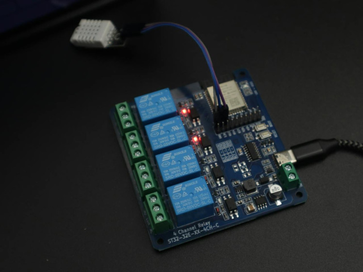
Upload the relay sketch and open the Serial Monitor at 115200 baud.
Check that you can see:
- Relay and DHT22 initialization
- ESP32 MAC address
- Wi-Fi connection
- ESP-NOW peer registration
If you do not see repeated DHT22 read failed messages, the sensor is working correctly.
Display ESP32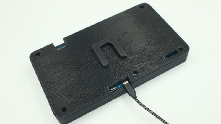
Next, upload the display sketch using the correct ESP32-S3 board settings.
Open the Serial Monitor at 115200 baud. The display should initialize, LVGL should start, and the dashboard should appear with working touch.
Finally, make sure both boards are connected correctly and ESP-NOW communication is working.
Step 10: Testing the ProjectTest the Relays
Tap each relay card on the Home page and check that the matching relay LED turns ON and OFF.
If a card stays at... and returns to its previous state, check the ESP-NOW MAC addresses and Wi-Fi channel.
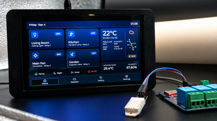
Check the four scene buttons:
- Home: R1 ON, R2 ON, R3 ON, R4 OFF
- Night: R1 OFF, R2 OFF, R3 ON, R4 ON
- Away: R1 OFF, R2 OFF, R3 OFF, R4 ON
- All Off: All relays OFF
The dashboard has four main pages:
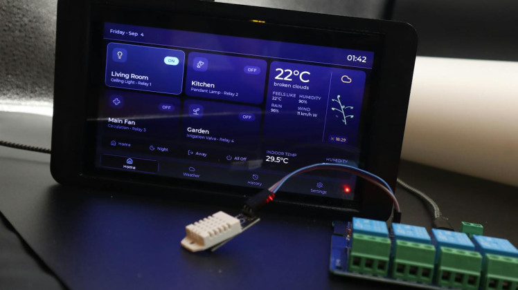
1 / 8
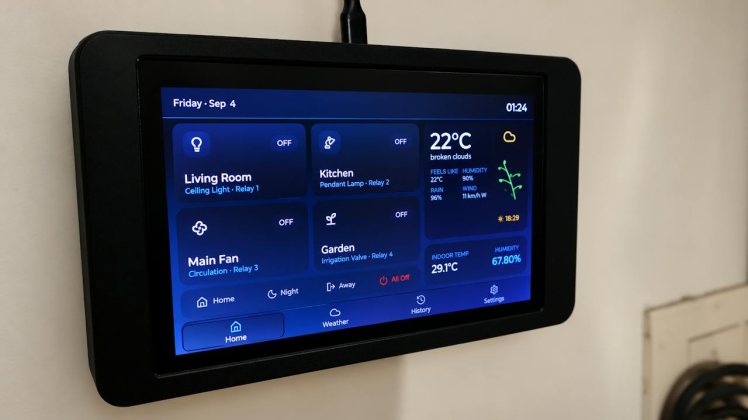
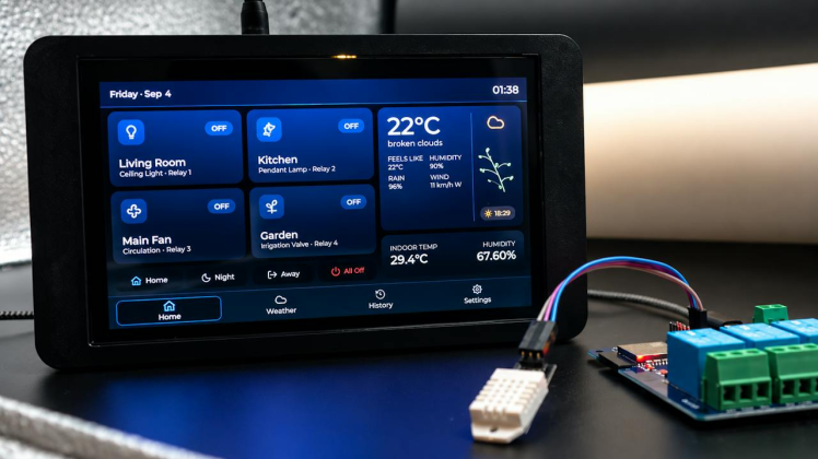
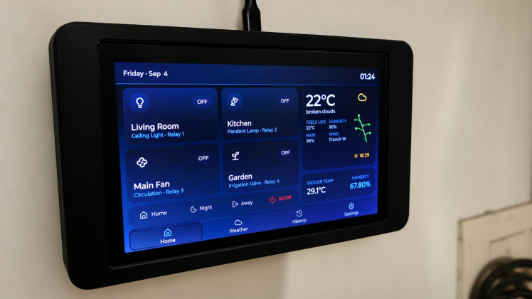
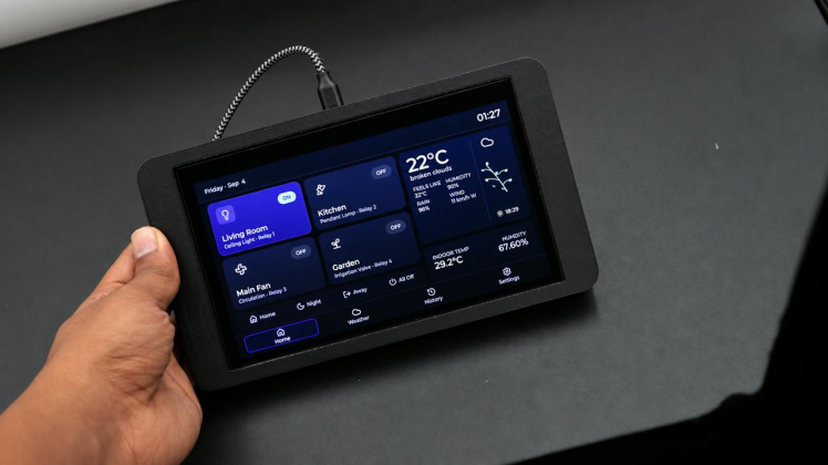
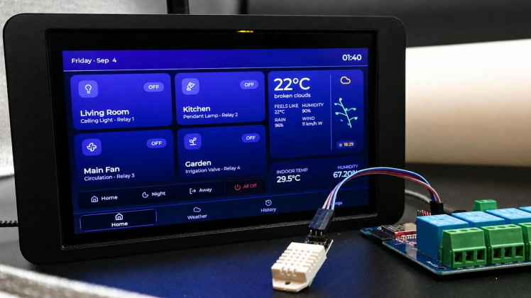
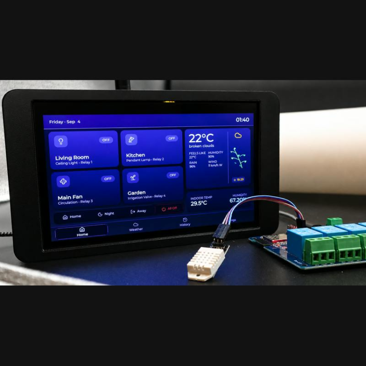
The Home page shows four relay controls for the Living Room, Kitchen, Main Fan, and Garden. It also includes scene buttons, current weather, and indoor temperature and humidity from the DHT22.
Weather Page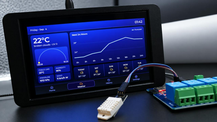
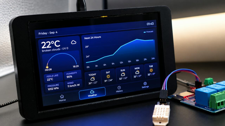
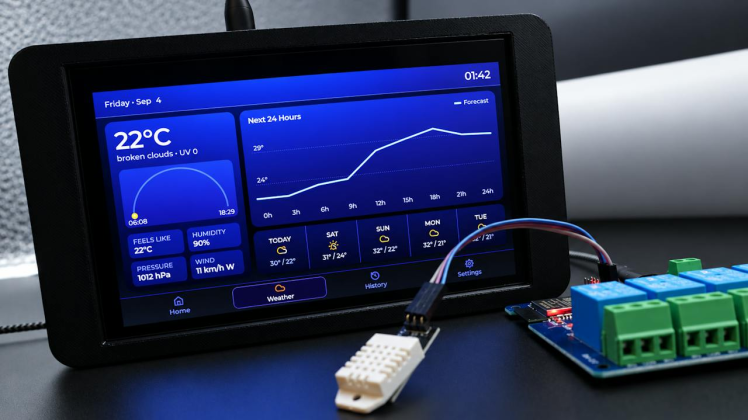
This page shows the current temperature, feels-like temperature, humidity, pressure, wind, UV index, sunrise, sunset, a 24-hour temperature chart, and a 5-day forecast.
History Page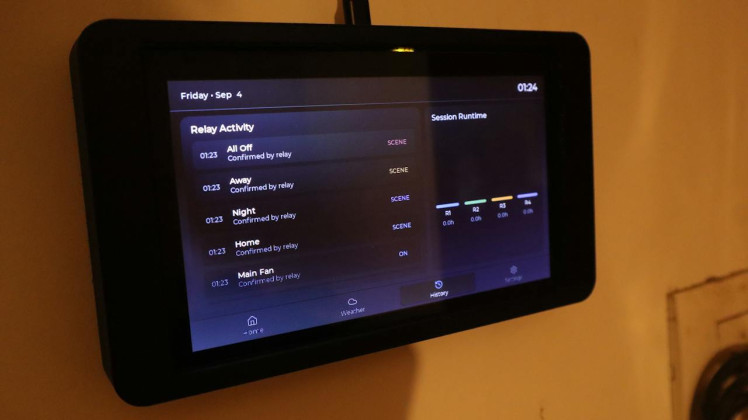
The History page shows the last 8 confirmed relay events and the session runtime of each relay.
The runtime data is stored only in RAM, so it resets when the ESP32 restarts.
Settings Page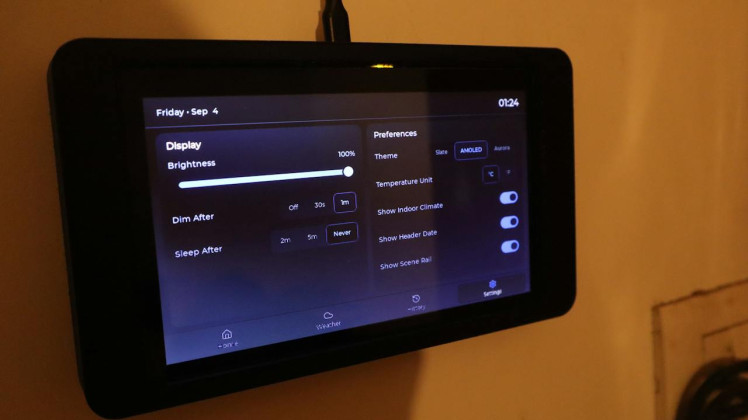
You can change:
- Brightness
- Dim and sleep time
- Theme: Slate, AMOLED, or Aurora
- Celsius or Fahrenheit
- Show/Hide Indoor Climate
- Show/Hide Date
- Show/Hide Scene buttons
The Smart Home Dashboard is now complete. The display can control four relays over ESP-NOW, show indoor sensor data, fetch weather information, and save the dashboard settings in flash memory. You can now customize the relay names, scenes, colors, and enclosure for your own home automation setup.
Schematics, diagrams and documents
CAD, enclosures and custom parts
Code
Credits
Related products



Leave your feedback...