
Esp32 Ble Communication

Made by pradeeplogu0 / Communication / Sensors
About the project
Will show you how to use BLE communication in ESP32 Controllers.
Project info
Difficulty: Moderate
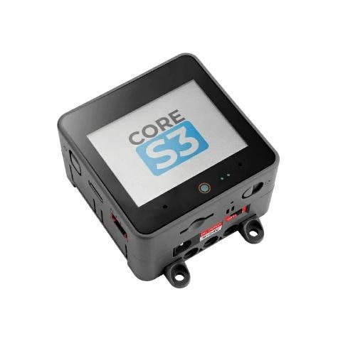
Platforms: M5Stack
Estimated time: 1 hour
License: GNU General Public License, version 3 or later (GPL3+)
Items used in this project
Hardware components

Story
In this tutorial, I'm going to show you how to trigger actions with Bluetooth using M5Stamp PICO and M5Stick C which are very cheap and High efficient ESP32 Controllers.
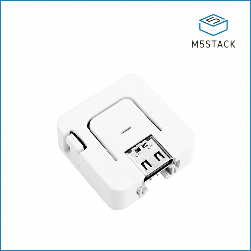
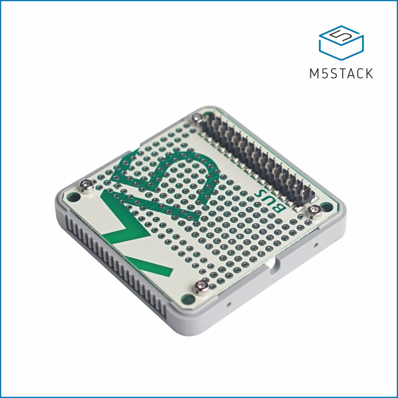
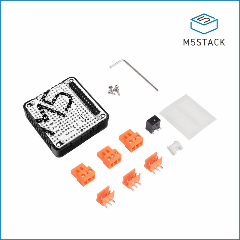
Components Required:
What is M5Stick and M5Stamp?

M5Stack is a technology company that designs and manufactures open-source development toolkit, including hardware, programming platform and IoT solutions. It was founded by Jimmy Lai in 2017 and based in Shenzhen, China.
M5Stack created the M5Stick and M5Stamps, which are both based on the ESP32 controller. The M5Stick C features an embedded TFT display and battery, while the M5Stamp has a small footprint and can be used in a variety of IoT products.
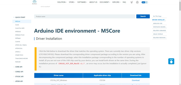
Set up M5Stamp and M5Stick with Arduino IDE by following these instructions.
https://docs.m5stack.com/en/quick_start/m5core/arduino
Flow :
M5Stick C will act as a BLE transmitter, while M5Stamp PICO will act as a BLE receiver. When Button A on the M5Stick is pressed, the M5Stamp's led turns green.
Coding for Transmitter:
#include <M5StickC.h>
#include "BLEDevice.h"
#include "BLEUtils.h"
#include "BLEServer.h"
#include "BLEBeacon.h"
BLEAdvertising *pAdvertising; // BLE Advertisement type
struct timeval now;
#define GPIO_DEEP_SLEEP_DURATION 1 // sleep x seconds and then wake up
RTC_DATA_ATTR static time_t last; // remember last boot in RTC Memory
RTC_DATA_ATTR static uint32_t bootcount; // remember number of boots in RTC Memory
#define BEACON_UUID "87b99b2c-90fd-11e9-bc42-526af7764f64" // UUID 1 128-Bit (may use linux tool uuidgen or random numbers via https://www.uuidgenerator.net/)
void setBeacon()
{
BLEBeacon oBeacon = BLEBeacon();
oBeacon.setManufacturerId(0x4C00);
oBeacon.setProximityUUID(BLEUUID(BEACON_UUID));
oBeacon.setMajor((bootcount & 0xFFFF0000) >> 16);
oBeacon.setMinor(bootcount & 0xFFFF);
BLEAdvertisementData oAdvertisementData = BLEAdvertisementData();
BLEAdvertisementData oScanResponseData = BLEAdvertisementData();
oAdvertisementData.setFlags(0x04); // BR_EDR_NOT_SUPPORTED 0x04
std::string strServiceData = "";
strServiceData += (char)26; // Len
strServiceData += (char)0xFF; // Type
strServiceData += oBeacon.getData();
oAdvertisementData.addData(strServiceData);
pAdvertising->setAdvertisementData(oAdvertisementData);
pAdvertising->setScanResponseData(oScanResponseData);
}
void setup() {
M5.begin();
Serial.begin(115200);
M5.Lcd.setTextColor(YELLOW); //Set the font color to yellow. 设置字体颜色为黄色
M5.Lcd.setRotation(3);
M5.Axp.ScreenBreath(10);
M5.Lcd.setTextColor(RED);
M5.Lcd.setCursor(3, 10);
M5.Lcd.setTextSize(2);
}
void loop() {
M5.update();
M5.Lcd.setCursor(3, 10);
if (M5.BtnA.wasReleased()) {
M5.Lcd.setTextColor(GREEN);
M5.Lcd.println("Triggred");
Serial.println("Trigger mode");
// Create the BLE Device
BLEDevice::init("BLE Receiver 01");
// Create the BLE Server
BLEServer *pServer = BLEDevice::createServer(); // <-- no longer required to instantiate BLEServer, less flash and ram usage
pAdvertising = BLEDevice::getAdvertising();
BLEDevice::startAdvertising();
setBeacon();
// Start advertising
pAdvertising->start();
Serial.println("Advertizing started...");
delay(1000);
pAdvertising->stop();
M5.Lcd.fillScreen(BLACK);
M5.Lcd.setCursor(3, 10);
}
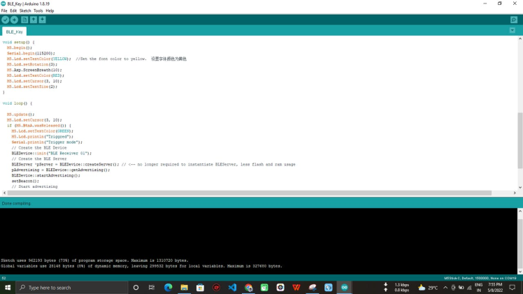
}Upload the above code to your M5Stick C Controller.
Coding for Receiver:
#include "Arduino.h"
#include <FastLED.h>
#include <BLEDevice.h>
#include <BLEUtils.h>
#include <BLEScan.h>
#include <BLEAdvertisedDevice.h>

// How many leds in your strip?
#define NUM_LEDS 1
#define DATA_PIN 27

// Define the array of leds
CRGB leds[NUM_LEDS];

String knownBLEAddresses[] = {"24:a1:60:53:06:3e"};
int RSSI_THRESHOLD = -100;
bool device_found;
int scanTime = 1; //In seconds
BLEScan* pBLEScan;
class MyAdvertisedDeviceCallbacks: public BLEAdvertisedDeviceCallbacks {
    void onResult(BLEAdvertisedDevice advertisedDevice) {
      for (int i = 0; i < (sizeof(knownBLEAddresses) / sizeof(knownBLEAddresses[0])); i++)
      {
        if (strcmp(advertisedDevice.getAddress().toString().c_str(), knownBLEAddresses[i].c_str()) == 0)
        {
          device_found = true;
          break;
        }
        else
          device_found = false;
      }
      Serial.printf("Advertised Device: %s n", advertisedDevice.toString().c_str());
    }
};
void setup() {
  Serial.begin(115200); //Enable UART on ESP32
  FastLED.addLeds<SK6812, DATA_PIN, RGB>(leds, NUM_LEDS);  // GRB ordering is typical
  Serial.println("Scanning..."); // Print Scanning
  BLEDevice::init("");
  pBLEScan = BLEDevice::getScan(); //create new scan
  pBLEScan->setAdvertisedDeviceCallbacks(new MyAdvertisedDeviceCallbacks()); //Init Callback Function
  pBLEScan->setActiveScan(true); //active scan uses more power, but get results faster
  pBLEScan->setInterval(100); // set Scan interval
  pBLEScan->setWindow(99);  // less or equal setInterval value
}
void loop()
{
  BLEScanResults foundDevices = pBLEScan->start(scanTime, false);

  for (int i = 0; i < foundDevices.getCount(); i++)
  {
    BLEAdvertisedDevice device = foundDevices.getDevice(i);
    int rssi = device.getRSSI();
    Serial.print("RSSI: ");
    Serial.println(rssi);
    if (rssi > RSSI_THRESHOLD && device_found == true)
    {
      Serial.println("Triggred");
      leds[0] = 0xf00000;
      FastLED.show();
      delay(200);
    }

  }
  // Now turn the LED off, then pause
  leds[0] = 0x00f000;
  FastLED.show();
  delay(200);
  pBLEScan->clearResults();   // delete results fromBLEScan buffer to release memory
}
In this above code, you have to change the BLE Address of your M5Stick C.

Here I have added my M5Stick C's BLE Address. Change this according to yours.
Outcome:
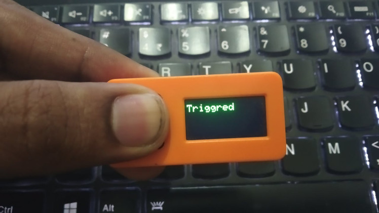
Once the Transmitter and Receiver codes have been uploaded to the M5Stick and M5Stamp, connect the M5Stamp to your PC and open the serial monitor, then click the Button A on the M5Stick C, which will display Triggered on the TFT Display.
Check the Serial Monitor Results whenever you see a triggered message in your M5Stick C.
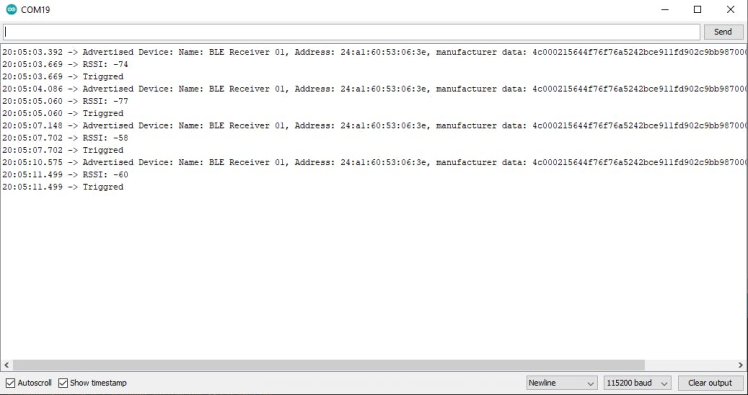
The name of the ESP Transmitter, RSSI, and Triggered Message will be displayed in the serial monitor. The Green led on the M5Stamp will blink.
The Green led will blink every time the button is pressed.
Credits
Related products


Leave your feedback...