
Diy Inclinometer Using Hexabitz Modules

Made by Aula_Jazmati / Environmental Sensing / Sensors
About the project
This project helps you measure the angle of a surface with respect to earth's gravitational field using Hexabitz modules.
Project info
Difficulty: Moderate
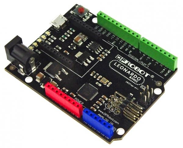
Platforms: DFRobot, STMicroelectronics
Estimated time: 1 hour
License: MIT license (MIT)
Items used in this project
Hardware components

Software apps and online services
Story
This project helps you measure the angle of a surface with respect to earth's gravitational field using Hexabitz modules.
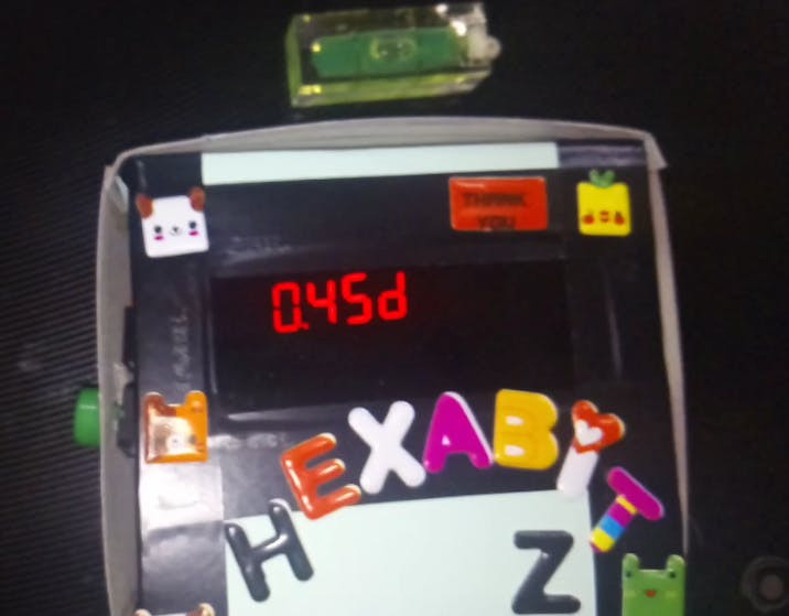
If the device measures an angle of 0.0 something degrees it means you have done a nice job at leveling the desk ^_^
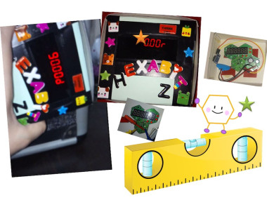
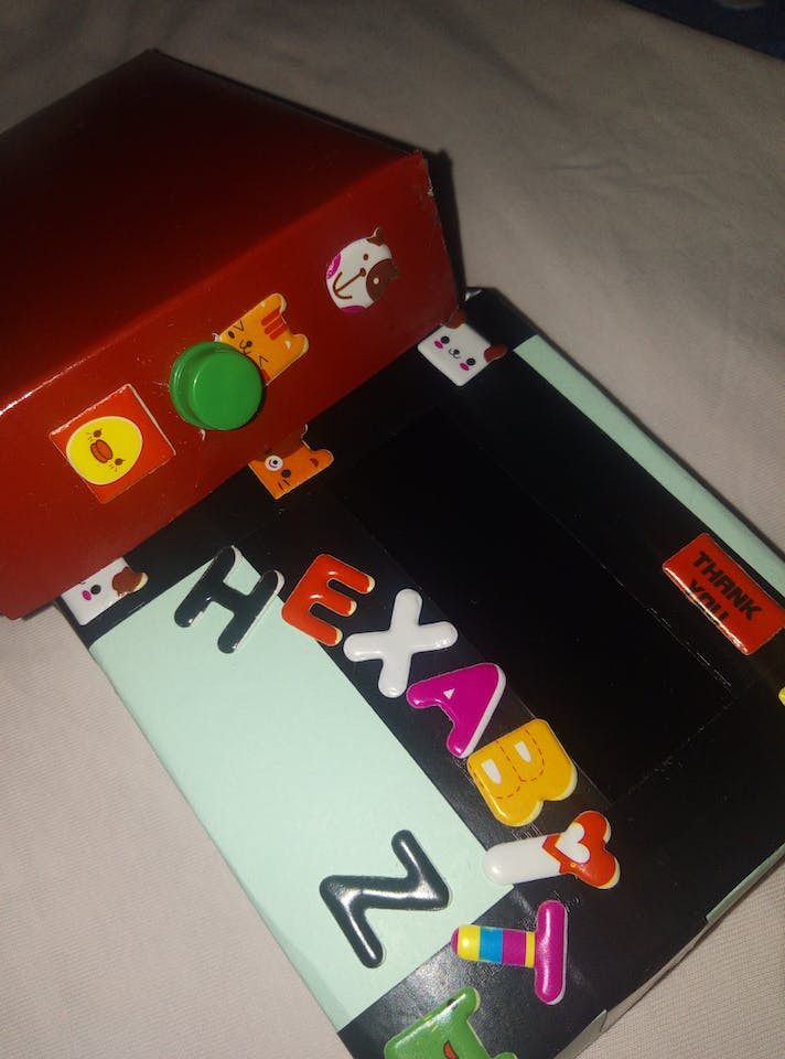
The project is also about designing a real product by yourself, this product is similar to another on the market as the search engines showed.
The project is stand-alone device, battery powered with the inclinometer and display built into the same product.
The product is found on search engines

The product is found on search engines
In this tutorial, I will take you through the steps that I followed to make this awesome project. I hope you will like it.
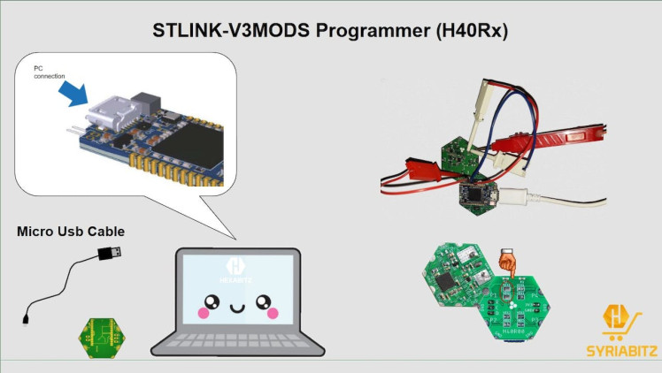
?️ Tools:1. STLINK-V3MODS Programmer (H40Rx):
H40Rx is a programmer module which contains STLINK-V3MODS stand-alone debugging and programming mini probe for STM32 micro-controllers (Hexabitz modules and other MCUs).
It supports the SWD (Serial Wire Debugging) interface for the communication with any STM32 micro-controller located on an application board.
It also provides bridge interfaces to several communication protocols, allowing for instance the programming of the target through boot-loader.
1 / 2 • STLINK-V3MODS Programmer (H40Rx)
")
STLINK-V3MODS Programmer (H40Rx)
2. Hexabitz IMU module (H0BR40):
H0BR4x is a 3-axis inertial measurement unit (IMU) combined with a 3-axis digital compass module based on STM32F0 MCU, LSM6DS3 IMU and LSM303AGR compass.
Hexabitz IMU module (H0BR40):3. 6 Digit Seven Segment (H3BR6x):
H3BR6x is a 6 digit seven segment interface module based on STM32G0 MCU.
- Features 0.36 inches, 6 digits, RED, 8-segment display LED, common anode.
- Use this module as an output display device. Connect it to other Hexabitz modules to display information in text or decimal form.
6 Digit Seven Segment (H3BR6x)
")
6 Digit Seven Segment (H3BR6x)
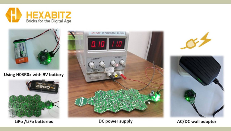
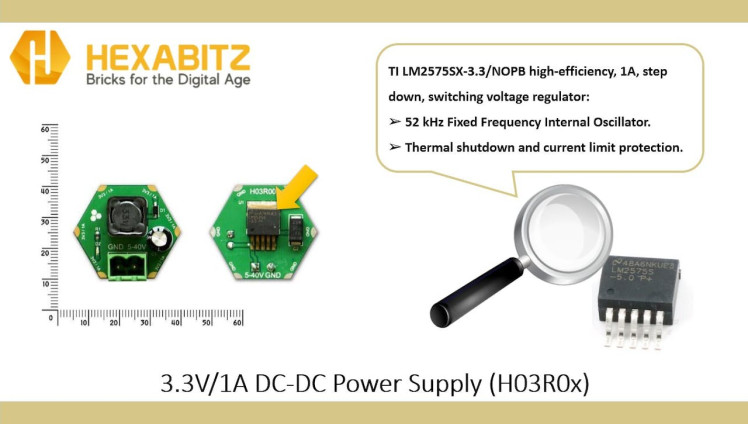
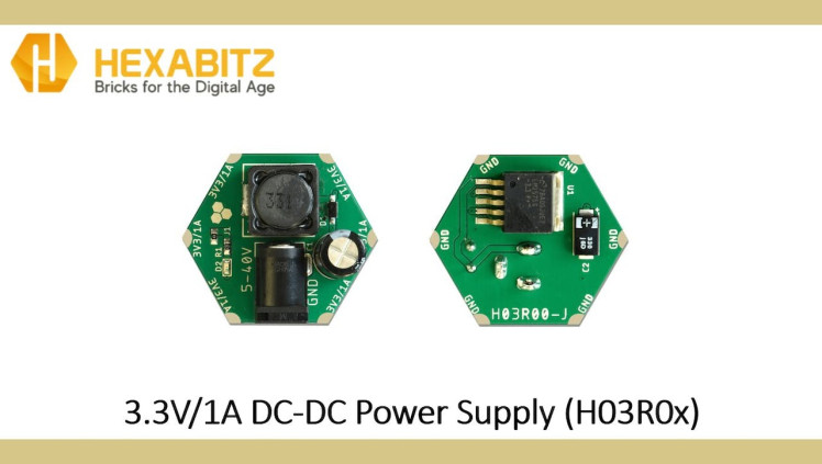
4. 3.3V/1A DC-DC Power Supply (H03R0x):
H03R0x is a compact DC-DC buck power supply with a 3.3V/1A DC output and 5-40V DC input. The output voltage is provided through Hexabitz SMD edge-pad connectors (3.3V on top and GND on bottom). The -T module version comes with a 5.08 mm terminal block connector for input voltage, while the -J comes with a DC power jack. Use this module to power all your Hexabitz creations (and other hardware) from a DC source (battery, AC/DC wall adapter, etc.)
1 / 4 • 3.3V/1A DC-DC Power Supply (H03R0x)
")
3.3V/1A DC-DC Power Supply (H03R0x)
The H0BR4x consist of 3-axis Accelerometer with Micro Electro Mechanical (MEMs) technology. It used to detect the angle of tilt or inclination along the X, Y, and Z axes as shown in the below figures.
Angle of Inclination

Angle of Inclination
Calculation of Angle of Inclination

Calculation of Angle of Inclination
Port Buttons/Switches API:You can connect any mechanical button or switch to any of the array ports at the modules using Hexabitz APIs.
Check out this article for Port Buttons/Switches
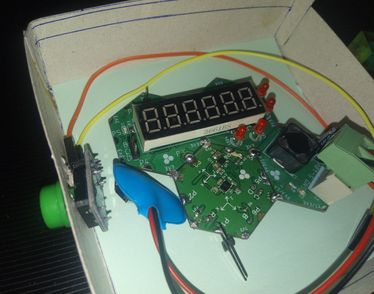
Port Buttons/Switches APISteps ?1) Plan the array and assemble the hardware:We prepare the project components and plan our array design by aligning modules side-by-side. Then we solder the modules together using Hexabitz Fixture.
The Schematics

The Schematics
2) Writing codes with STM32CubeIDE software:Check out this article for writing code with STM32CubeIDE.
· Fixed topology file: Inter-array communication in Hexabitz is done using a routing table stored in a special header (.h) file. This header file describes the number of modules and how they are connected to each other as well as other important information for the array; hence, it is called a topology header file. Currently, you need to make a topology file manually.
After creating the topology for the two modules (H0BR4x, H3BR6x) and determining their configurations, we add the topology for each module. See this link for help in creating a topology file.
/*
 BitzOS (BOS) V0.2.7 - Copyright (C) 2017-2022 Hexabitz
 All rights reserved

 File Name     : topology.h
 Description   : Array topology definition.

 */

/* Define to prevent recursive inclusion -------------------------------------*/
#ifndef __topology_H
#define __topology_H
#ifdef __cplusplus
 extern "C" {
#endif

/* Includes ------------------------------------------------------------------*/
#include "stm32f0xx_hal.h"

#define __N	2					// Number of array modules

// Array modules
#define _mod1	1<<3
#define _mod2	2<<3

// Topology
static uint16_t array[__N ][7] ={
	{_H0BR4, 0, 0, _mod2 | P3, 0, 0, 0}, 								 // Module 1
	{_H3BR6, 0, 0,_mod1 | P3, 0, 0, 0},					    			 // Module 2
};

// Configurations for duplex serial ports
#if ( _module == 1 )
	#define	H0BR4	1
	#define	_P1pol_normal	1
	#define	_P2pol_normal	1
	#define	_P3pol_normal	1
	#define	_P4pol_normal	1
	#define	_P5pol_normal	1
	#define	_P6pol_normal	1
#endif

#if ( _module == 2 )
	#define	H3BR6			1
	#define	_P1pol_normal	1
	#define	_P2pol_normal	1
	#define	_P3pol_reversed	1
	#define	_P4pol_normal	1
	#define	_P5pol_normal	1
	#define	_P6pol_normal	1

#endif


#ifdef __cplusplus
}
#endif
#endif /*__ topology_H */

/************************ (C) COPYRIGHT HEXABITZ *****END OF FILE****/
Then go to project.h as shown in the photo below and UN-comment the header.
project.h file

project.h file
Press on main.c and define sensor accelerometer variables, tilt angle variable and button state variable in the main.c file of the module IMU (H0BR40):
float x, y, z, ang2;
int button1 = 0;
Define the button and link it to its callbacks in the UserTask function like this:
AddPortButton(MOMENTARY_NO,P1); // Define a button connected to port P1
SetButtonEvents(P1, 1, 1, 0, 0, 0, 0, 0, 0, 0); // Activate a click events
These events can be linked to user callbacks to execute some tasks. Add the following callback to your code in main.c to make use of button events:
void buttonClickedCallback(uint8_t port)
{
if(port == P1) 	{
button1 = 1; IND_blink(200);	}
Delay_ms(10);
}
Then we obtain the filtered and calibrated values of the accelerometer in units of g using the following API from the H0BR40 factsheet:
H0BR40 accelerometer in units of g API

H0BR40 accelerometer in units of g API
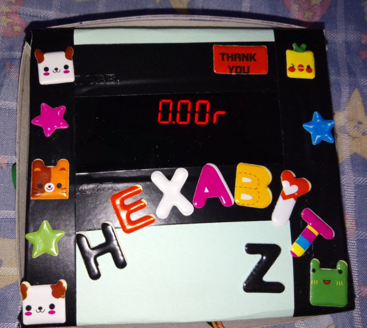
In the UserTask function, we now write our repeated code that checks by the state of the button variable.
If the button is not pressed, the tilt angle appears in degrees where a message is sent to the Seven Segment (H3BR6x) module. If the button is pressed, the angle of inclination is shown in one radian where a message is sent to the Seven Segment (H3BR6x) module too.
Show a float value on the display Message. The parameter unit refers to the value unit

Show a float value on the display Message. The parameter unit refers to the value unit
These values were first monitored using the STM32CubeIDE debugging function to monitor live expressions.
while(1){
    	SampleAccG (&x, &y, &z);
    	if (button1 == 0){
    		ang2 = (atan2(x,z))* 57.3;
		    memcpy(&messageParams[0], &ang2, 4);
		    messageParams[4] = 2;
		    messageParams[5] = 'd';
		    messageParams[6]=0;
		    SendMessageToModule(2,CODE_H3BR6_SevenDisplayQuantities,7);	}
    	if (button1 == 1){
    		ang2 = atan2(x,z);
    		memcpy(&messageParams[0], &ang2, 4);
    		messageParams[4] = 2;
    		messageParams[5] = 'r';
    		messageParams[6]=0;
    		SendMessageToModule(2,CODE_H3BR6_SevenDisplayQuantities,7);	}
	}
In the future, we are going to build a Digital Inclinometer which can be monitored using an Android application and H23R3(BlueNRG-M2 BLE 5) module ??
BlueNRG-M2 BLE 5 Module

BlueNRG-M2 BLE 5 Module
The reason for planning to using a remote display like a mobile phone is that we can monitor the values from IMU without having to look at the hardware, this would come very handy when the IMU is placed on a drone or some other inaccessible locations[4].
Android APK File for Inclinometer

Android APK File for Inclinometer
3) Test the System ? ? ? ? ☑️

You can use DC-DC power module (H03R0) with 9V battery to power your project. Note that it's better to write the code using power from USB cable connection without DC-DC power module (to avoid power confusion and reset states). Once done, you can insert the batteries and then remove the USB cable.
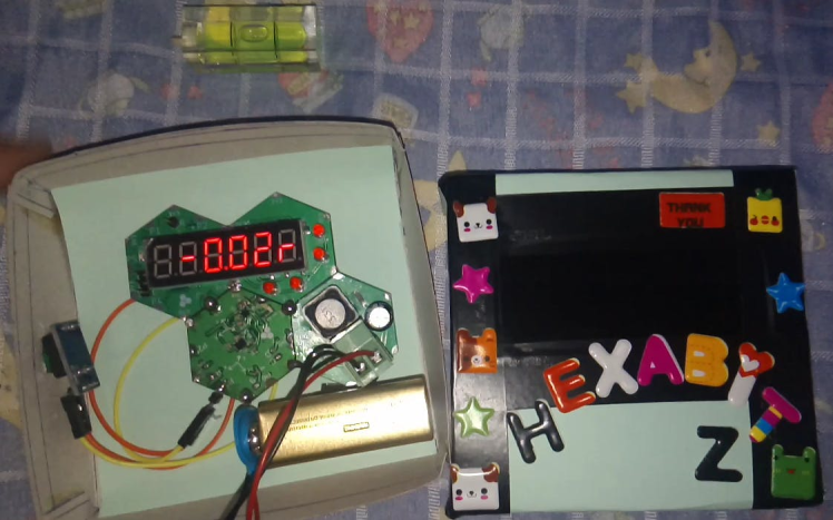
You can now use your project to make perfect shelves.
1 / 2
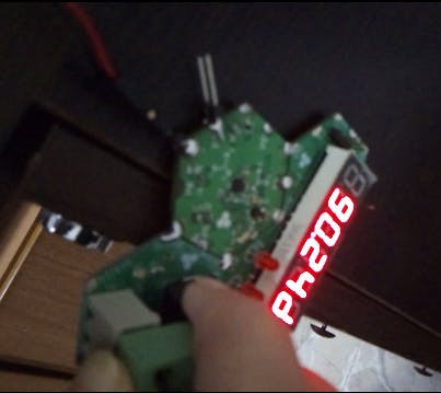
1 / 3 • Radian / Degree Button

Radian / Degree Button
Happy Doing It Yourself.
Please feel free to leave a comment here if you have any questions or concerns regarding this project ?
References:
[1] https://hexabitz.com/modules/
[2] https://hexabitz.com/wiki/
[3] https://hexabitz.com/product-category/accy/
[4] https://circuitdigest.com/microcontroller-projects/arduino-inclinometer-using-mpu6050
Schematics, diagrams and documents
Code
Credits
Related products


Leave your feedback...