
Display Time On M5stack Cores3 Esp32-s3

Made by Ron / Clocks / Displays / Notifications / Sensors
About the project
In this project you can learn how to use Visuino to display time on the M5Stack CoreS3 using internal RTC module.
Project info
Difficulty: Easy
Platforms: Arduino, Visuino, M5Stack
Estimated time: 1 hour
License: GNU General Public License, version 3 or later (GPL3+)
Items used in this project

Story
This project was made by Visuino user Rafał. Visit his youtube channel here: https://www.youtube.com/@Edappl/videos
Step 1: What You Will Need1 / 2
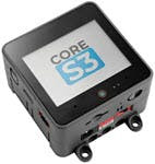
- M5Stack CoreS3 ESP32S3 loT Development Kit
- Visuino program: Download Visuino
1 / 2
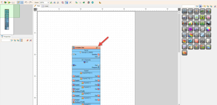
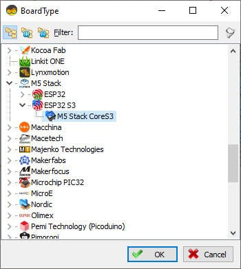
Start Visuino as shown in the first picture Click on the "Tools" button on the Arduino component (Picture 1) in Visuino When the dialog appears, select "M5 Stack CoreS3" as shown on Picture 2
Step 3: In Visuino Add & Set Components1 / 4
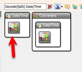
Add "Decode(Split) Date/Time" component
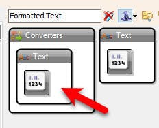
- Add "Formatted Text" component
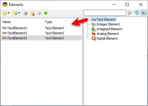
- Double click on the "FormattedText1" and in the Elements window drag 3X "Text Element" to the left side and close the Elements window
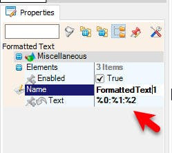
- Select "FormattedText1" and in the properties window set "Text" to: %0:%1:%2
(Where %0 represents TextElement1, %1 represents TextElement2, %2 represents TextElement3)
Step 4: In Visuino Set M5 Stack CoreS3 Display1 / 5
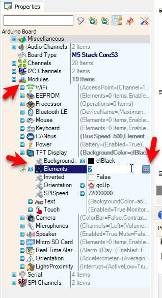
- Select "M5 Stack CoreS3" board and in the properties window expand "Modules">"TFT Display">"Elements" and click on the 3 dots button
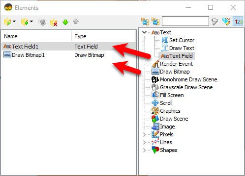
- In the "Elements" window drag "Text Field" to the left side
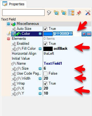
- In the "Elements" window drag 6X "Draw Scene" to the left side, and in the properties window set "Color" to $FF0080FF, "Fill Color" to aclBlack, "Size" to 6, "Width" to 20, "X" to 20, "Y" to 10
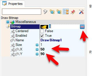
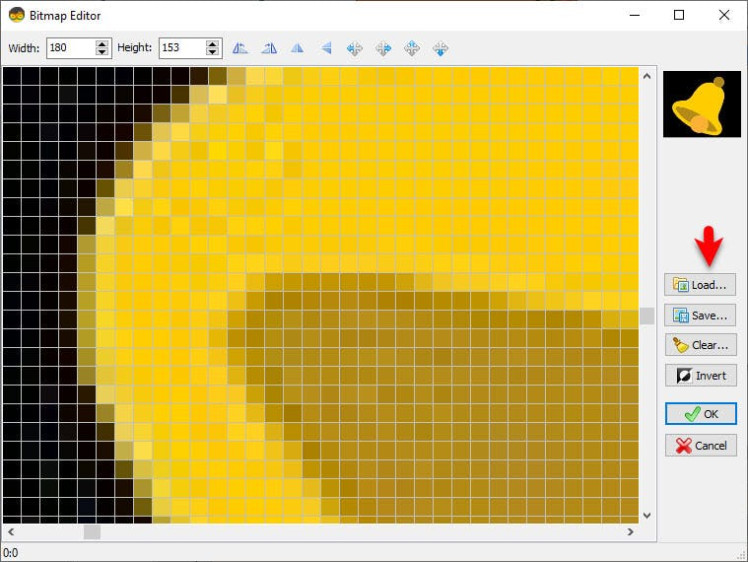
- In the "Elements" window drag "Draw Bitmap" to the left side, and in the properties window set "X" to 50, "Y" to 90, Select "Bitmap" and click on the 3 dot button and in the Bitmap Editor Load the bitmap that is attached above (the Bell)
- Close All the windows
1 / 2
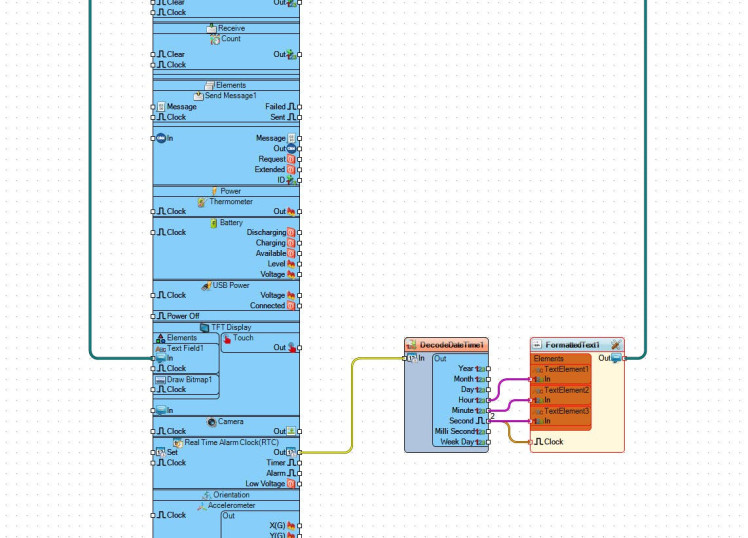
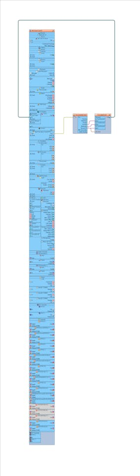
- Connect M5 Stack CoreS3>Real Time Alarm Clock(RTC) pin [Out] to "DecodeDateTime1" pin [In]
- Connect "DecodeDateTime1" pin [Hour] to "FormattedText1" > "TextElement1" pin [In]
- Connect "DecodeDateTime1" pin [Minute] to "FormattedText1" > "TextElement2" pin [In]
- Connect "DecodeDateTime1" pin [Second] to "FormattedText1" > "TextElement3" pin [In]
- Connect "DecodeDateTime1" pin [Second] to "FormattedText1" pin [Clock]
- Connect "FormattedText1" pin [Out] to M5 Stack CoreS3>TFT Display>Text Field1 pin [In]
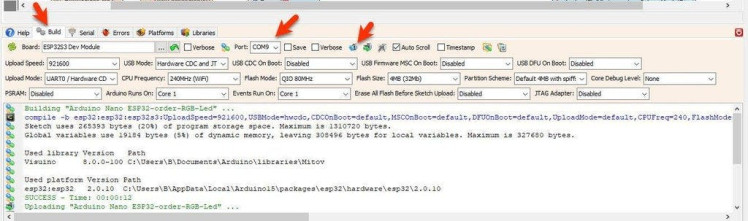
In Visuino, at the bottom click on the "Build" Tab, make sure the correct port is selected, then click on the "Compile/Build and Upload" button.
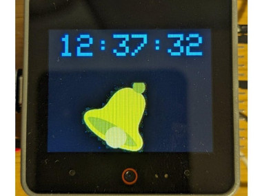
Step 7: PlayAfter uploading the project to the M5 Stack CoreS3 the board will start to display Time.
Congratulations! You have completed your LED project with Visuino. Also attached is the Visuino project, that was created for this Tutorial. You can download and open it in Visuino: https://www.visuino.com
Schematics, diagrams and documents
Code
Credits
Related products


Leave your feedback...