
Depth Camera & Robot Arm: Object Recognition&pick-and-place
Made by Elephant Robotics / Robotics
About the project
This project combines machine learning and robotics to enable a robotic arm to recognize and pick up a wooden block, demonstrating the poten
Project info
Difficulty: Moderate
Platforms: Raspberry Pi, ROS, Elephant Robotics
Estimated time: 1 hour
License: GNU General Public License, version 3 or later (GPL3+)
Items used in this project
Hardware components

Software apps and online services
Story
As technology continues to advance, we're seeing more and more sophisticated robotic arms and humanoid robots being developed. In order to keep up with the times and enhance my knowledge of robotics, I recently purchased a myCobot pro 600 robotic arm. My main goal is to use this device to learn about robotic arm control and machine vision projects, which will be beneficial for my future practical applications. In this blog post, I'll be documenting my experience using the myCobot pro 600 in conjunction with a depth camera to achieve object tracking and grasping.
Next, I'll introduce the equipment I'll be using.
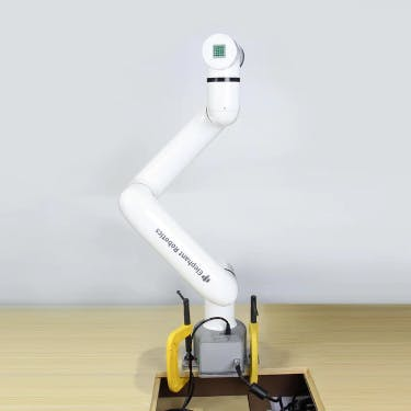
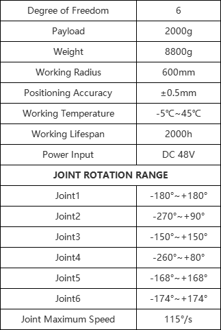
EquipmentmyCobot pro 600The myCobot pro 600 is a six-axis robotic arm that offers a maximum working radius of 600mm and a maximum payload capacity of 2kg at its end effector. It is equipped with a harmonic reducer motor and features a Raspberry Pi 4B as its core controller, running on an Ubuntu 20.0 system. I chose this robotic arm for several reasons:
● It does not require an additional computer for control, as it can be controlled directly using the Raspberry Pi.
● Its working radius and payload capacity are perfectly suited for my intended use case.
● The manufacturer, Elephant Robotics, has designed a visual programming software called RobotFlow, which allows for drag-and-drop programming and makes it easy to create and execute tasks.
SPECIFICATIONS
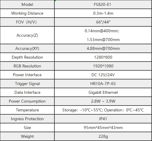
A depth camera can capture depth information and obtain three-dimensional coordinates, distance, size, and volume of objects. It uses various algorithms and techniques such as structured light, time-of-flight, and stereo vision to measure the depth of objects. In machine vision applications, a depth camera can be used for tasks such as point cloud segmentation, object recognition, and 3D reconstruction.

SPECIFICATIONS
I've been using a robotic arm for a while now, and most of the time I've been using it to perform some repetitive tasks, such as picking up objects along a path. However, if that's all it can do, the robotic arm is not capable of doing many tasks that require human-like dexterity and judgment. When we work, our hands and eyes need to coordinate with each other, and we need to give the robotic arm a 'eye' that can provide depth information, such as a depth camera.
Today, I want to record the process of using a robotic arm equipped with a camera to pick up objects, not just a simple flat pickup, but a pickup that can judge the height of the object based on the depth information obtained.
Next, I'll give a brief overview of the project's structure.
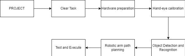
Clear Task: First, we need to clarify our target, which is to use a depth vision-enabled robotic arm to pick up a wooden block.
Hardware Preparation: The robotic arm used is mycobot pro 600, and the depth camera used is FS820-E1.
Hand-eye calibration: We need to perform hand-eye calibration between the robotic arm and the camera to establish the coordinate transformation relationship between them. Through hand-eye calibration, we can determine the position and orientation of the robotic arm's end effector relative to the camera coordinate system, thus enabling accurate visual guidance and grasping.
Object Detection and Recognition: We need to detect and recognize the object to be picked up, which is a wooden block. We will train an algorithm to recognize the wooden block and use large amounts of data to enable the machine to accurately identify the object.
Robotic Arm Path Planning: After recognizing the object, the robotic arm needs to plan its motion path to reach the pickup point. We will use the 3D coordinates of the object returned by the depth camera to guide the robotic arm to the pickup point.
Test: After completing the above steps, we need to test the system repeatedly, adjusting the robotic arm's motion path and grasping method to achieve the desired outcome.
Execute: After testing, we can execute the task using the trained model and calibrated robotic arm.
Now that we have introduced the project's structure, let's start with hand-eye calibration.
Hand-eye calibrationUsually, for robotic arm visual grasping tasks, hand-eye calibration is necessary. Hand-eye calibration is the process of associating the robotic arm's coordinate system with the depth camera's coordinate system. Through hand-eye calibration, we can determine the position and orientation of the robotic arm's end effector relative to the camera coordinate system, thus enabling accurate visual guidance and grasping.
Step 1:
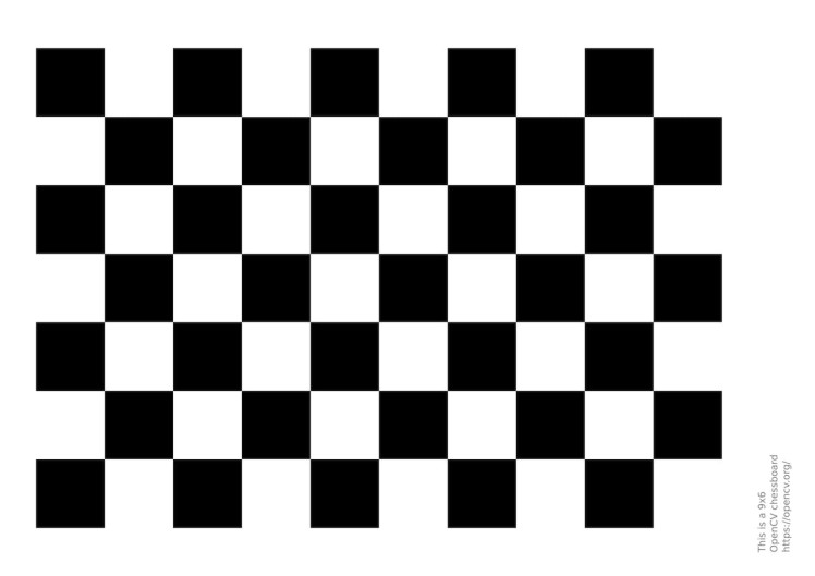
We need to prepare a calibration plate: Select a black and white checkerboard as the calibration plate, the geometric structure of the checkerboard is very regular, and the edges and corner positions of the squares can be accurately calculated and modeled. This allows the calibration algorithm to accurately estimate the geometric relationship between the camera and the checkerboard.
Step 2:
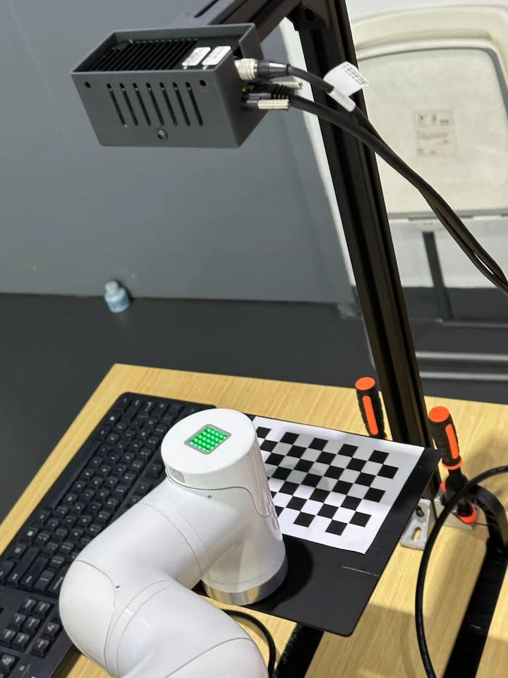
Fixed depth camera and robotic arm
I want to do eye-in-hand mode, which means the camera's position will not change with the robotic arm's movement.
Step 3:
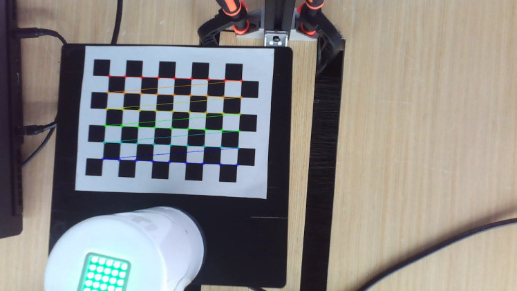
Match feature points
Place the calibration plate within the camera's field of view and rotate it multiple times to capture images that provide rich visual information. For each calibration plate image, use a corner detection algorithm to extract the coordinate features of the intersection points of the grid lines on the plate.
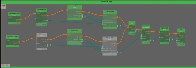
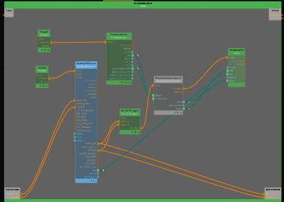
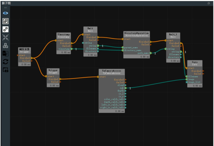
We use the RVS (Robot Vision Suite) software that comes with the camera to pre-write the methods for capturing images, extracting feature points, and matching feature points.
Step 4:
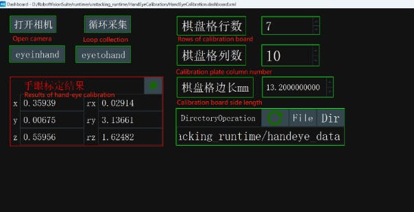
Compute calibration coordinates
Obtain 20 sets of data with different angles and positions of feature points, and then use the algorithm provided by RVS to calculate the eye-to-hand calibration values in the program. Record the hand-eye calibration results for later use in transforming the robotic arm's coordinate system and the camera's coordinate system.
That's it for hand-eye calibration, and now we can move on to training the machine to recognize the object.
Object detection and recognitionFirst, we need to collect our test object, which is a wooden block. We use an open-source software called LabelMe to create and edit image annotation data sets. Its purpose is to simplify the image annotation process and provide annotated data for machine learning and computer vision tasks.
Collecting images of the test object
Just like before, the more images we collect, the more accurate the data will be. Save them in a specified path.
Installing LabelMe
Install the necessary libraries in Python to use LabelMe.
pip install PyQt5
pip install labelme
Annotation process
Open LabelMe, find the path where the collected images are saved, and then click Create Polygons to draw a red boundary around the wooden block. Give the annotated result a name, such as "wooden block, " and repeat this step to annotate all the collected images.

These manually annotated images of the wooden block are used to train the machine to recognize the object. Next, we need to train an AI model using the RVS software, which has this algorithm. We only need to submit the annotated images to the AI training function, and it will generate a Train output file folder, where we can get the weight file of the annotated data.
AI Inference
AI inference makes it possible for the trained model to apply to real-world scenarios, using the trained parameters and weights to process new input data and generate corresponding output results.
1. Use the FilterBoxList algorithm (renamed as "Point Cloud Height Sorting") to select the wooden blocks and sort them according to their Z-axis coordinate values in the point cloud list. Adjust the property values of this algorithm according to the following requirements.
2. Use the FindElement algorithm to obtain a suitable plane. In the algorithm properties, select the type as "Plane" and adjust the distance_threshold property to select a suitable plane. You can open the point cloud visualization property to view the selected plane.
3. Use the MinimumBoundingBox algorithm (renamed as "Get Outer Box") to obtain the center coordinate of the plane. In the algorithm properties, select the type as "ApproxMVBB" and provide a ref_pose, which connects to the previous "TowardsDownPose" algorithm, indicating a rotation of 180° around the X-axis, with the Z-axis facing down, so that the robot can pick up the object. You can open the "GetBoxCube" property panel and display the box and box_pose visualization properties to show the calculated center point of the plane.
In summary, the goal of this operation is to select wooden blocks from the point cloud, sort them by height, find a suitable plane, and calculate the center coordinate of the plane. This process may be used for further robotic tasks, such as grasping or path planning.
Combined with hand-eye calibration, the coordinate information of the wooden block can be obtained when the wooden block is identified. In this way, the coordinates of the wooden block relative to the robotic arm are obtained.
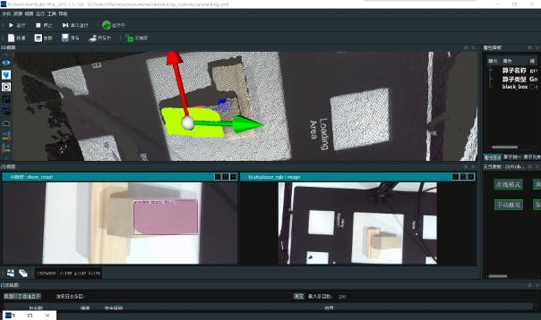
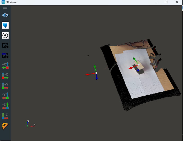
The picture below is the simulation 3D environment in RVS. The one with coordinates on the far left is the sign of the coordinate system of the depth camera.
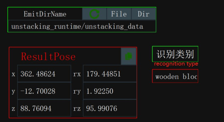
In the previous operation, we obtained the resultPose, which is the coordinate of the wooden block relative to the robotic arm. With the coordinate, we can control the robotic arm to move its end effector to the coordinate location of the object to be measured. Here's some code for implementing path planning:
import _thread
import socket
import json
import time
import sys
import math
import copy
import numpy as np
from RoboFlowSocket import RoboFlowSocket

#Conversion between rotation matrix and Euler angles
def CvtRotationMatrixToEulerAngle(pdtRotationMatrix):
    pdtEulerAngle = np.zeros(3)

    pdtEulerAngle[2] = np.arctan2(pdtRotationMatrix[1, 0], pdtRotationMatrix[0, 0])

    fCosRoll = np.cos(pdtEulerAngle[2])
    fSinRoll = np.sin(pdtEulerAngle[2])

    pdtEulerAngle[1] = np.arctan2(-pdtRotationMatrix[2, 0], (fCosRoll * pdtRotationMatrix[0, 0]) + (fSinRoll * pdtRotationMatrix[1, 0]))
    pdtEulerAngle[0] = np.arctan2((fSinRoll * pdtRotationMatrix[0, 2]) - (fCosRoll * pdtRotationMatrix[1, 2]), (-fSinRoll * pdtRotationMatrix[0, 1]) + (fCosRoll * pdtRotationMatrix[1, 1]))

    return pdtEulerAngle

def CvtEulerAngleToRotationMatrix(ptrEulerAngle):
    ptrSinAngle = np.sin(ptrEulerAngle)
    ptrCosAngle = np.cos(ptrEulerAngle)

    ptrRotationMatrix = np.zeros((3, 3))
    ptrRotationMatrix[0, 0] = ptrCosAngle[2] * ptrCosAngle[1]
    ptrRotationMatrix[0, 1] = ptrCosAngle[2] * ptrSinAngle[1] * ptrSinAngle[0] - ptrSinAngle[2] * ptrCosAngle[0]
    ptrRotationMatrix[0, 2] = ptrCosAngle[2] * ptrSinAngle[1] * ptrCosAngle[0] + ptrSinAngle[2] * ptrSinAngle[0]
    ptrRotationMatrix[1, 0] = ptrSinAngle[2] * ptrCosAngle[1]
    ptrRotationMatrix[1, 1] = ptrSinAngle[2] * ptrSinAngle[1] * ptrSinAngle[0] + ptrCosAngle[2] * ptrCosAngle[0]
    ptrRotationMatrix[1, 2] = ptrSinAngle[2] * ptrSinAngle[1] * ptrCosAngle[0] - ptrCosAngle[2] * ptrSinAngle[0]
    ptrRotationMatrix[2, 0] = -ptrSinAngle[1]
    ptrRotationMatrix[2, 1] = ptrCosAngle[1] * ptrSinAngle[0]
    ptrRotationMatrix[2, 2] = ptrCosAngle[1] * ptrCosAngle[0]

    return ptrRotationMatrix

# Path planning for grabbing locations
def compute_end_effector_pose(current_pose, tool_pose):
    # Extract rotation matrix and translation vector from pose matrix
    current_rotation = current_pose[:3,:3]
    current_translation = current_pose[:3,3]
    tool_rotation = tool_pose[:3,:3]
    tool_translation = tool_pose[:3,3]

    # Calculate the pose of the tool coordinate system in the base coordinate system
    new_rotation = np.dot(current_rotation, tool_rotation)
    new_translation = np.dot(current_rotation, tool_translation) + current_translation

    # Combine the rotation matrix and translation vector to get a new pose matrix
    new_pose = np.eye(4)
    new_pose[:3,:3] = new_rotation
    new_pose[:3,3] = new_translation

    return new_pose
Let's see how it works!
1 / 2
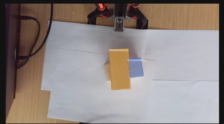
I reserved a certain distance between the robotic arm's end effector and the wooden block, which is the distance for the robotic arm to grasp the object. I placed several white papers on the table because the color of the object to be measured and the table surface are similar, making it easier to recognize the object.
Problems encountered:1. At first, I considered how to establish a connection between the robotic arm and the depth camera. It was a bit complex to establish communication between the two processors, but I finally used Python's socket library to control the myCobot pro 600.
2. During testing, there was a deviation in the coordinates, and I found that the reason was that after the eye-catching operation, the position of the robotic arm and depth camera was fixed and could not be adjusted.
3. The recognition of the object was slow, and the reason was that the object to be measured and the table surface had similar textures, making it difficult to recognize. (I placed white papers on the table to improve recognition) The machine is still a machine, and it can't beat human eyes.
SummaryThe current project is still not perfect, and I plan to add a gripper to the end effector to pick up the wooden block. However, this cannot be applied to real-world scenarios, as it is not necessary for us to pick up wood. If we change the perspective, if there are a pile of parts scattered on the table, using a robotic arm to classify them would be helpful. Because finding a part in a pile of messy parts is a very painful thing, if you have encountered this problem, you will understand what I mean.
If you have any ideas or interesting suggestions, please leave a comment below. If you think this article is helpful, give me a thumbs up or leave a comment!
Credits
Elephant Robotics
Elephant Robotics is a technology firm specializing in the design and production of robotics, development and applications of operating system and intelligent manufacturing services in industry, commerce, education, scientific research, home and etc.
Related products


Leave your feedback...