
Data Fusion With Hexabitz Imu Module (h0br40)
About the project
Build a tiny IMU data fusion logger by connecting Hexabitz IMU module to Hexabitz Micro SD card module.
Project info
Items used in this project
Hardware components

Story
Data fusion is a technique to integrate different types of data to a single unit to provide a more reliable representation of tracking measurement.
Today, data fusion can be found in many applications such as tracking and surveillance system as well as on mobile robots, wearables, and virtual realityapplications.
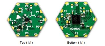
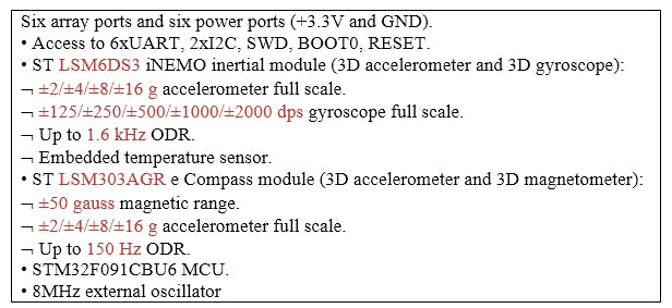
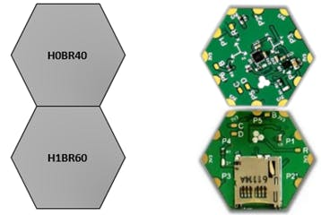
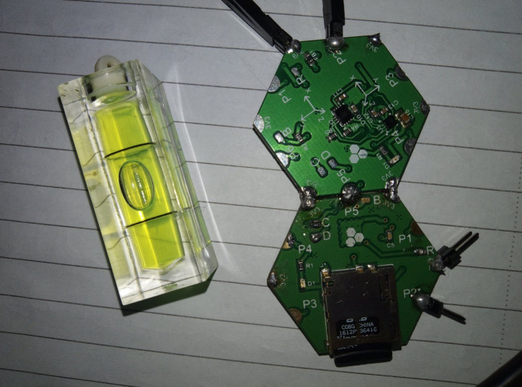
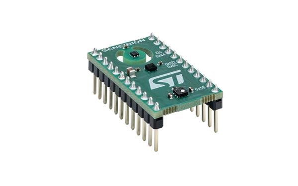
In this project, we have used a Hexabitz IMU module (H0BR40) that based on STM32F0 MCU, LSM6DS3 IMU and LSM303AGR compass forattitude estimation and storing the data by Micro SD card module.
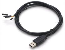
Tools:1. FTDI USB to UART Serial cable
2. Hexabitz IMU module (H0BR40)
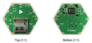
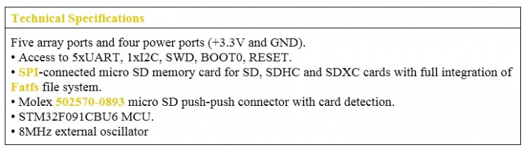
3. Micro SD Card Module (H1BR60)
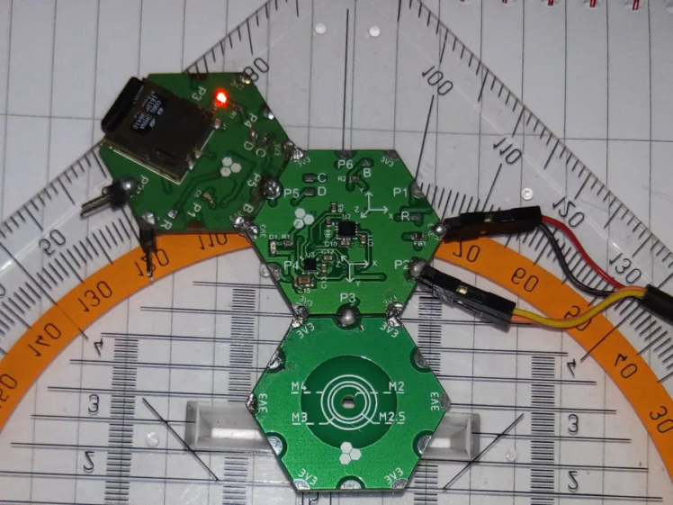
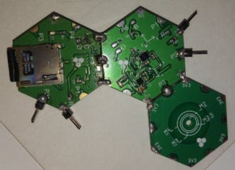
Plan the array and assemble the hardware:
· We prepare the project components and plan our array design by aligning modules side-by-side
· Then we solder the modules together using Hexabitz Fixture.
Writing codes with Keil uVision
Check out this article for writing code with Keil uVision
https://hexabitz.com/docs/how-to/start-coding-with-hexabitz/writing-code-with-keil-uvision/
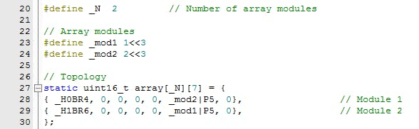
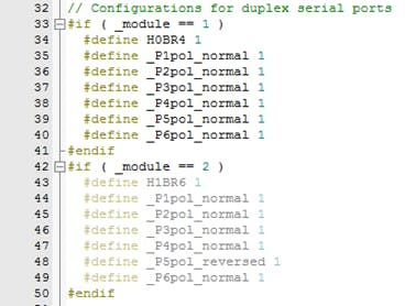
Fixed topology file: Inter-array communication in Hexabitz is done using a routing table stored in a special header (.h) file. This header file describes the number of modules and how they are connected to each other as well as other important information for the array; hence, it is called a topology header file. Currently, you need to make a topology file manually (by modifying an existing one and adding the modules number so that they can communicate with each other and know their neighbors.) https://hexabitz.com/docs/how-to/make-a-pre-built-array-topology-file/

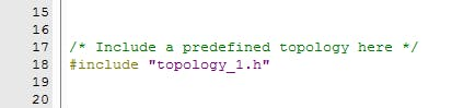
Then go to project.h and un-comment the header.
Press on main.c after creating topology to create your code.
1- Record the measurements on the memory card
· You must know that we have two projects one for IMU module (H0BR40) and the other for micro SD (H1BR6) module.
· We need to build our files for both projects.
· BOS offers a powerful remote memory read/write access functionality through specific Messages and APIs. This allows a module to access and modify almost any RAM or Flash memory location in another module in the array, thus, providing powerful synchronization and granular control.
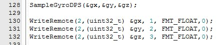
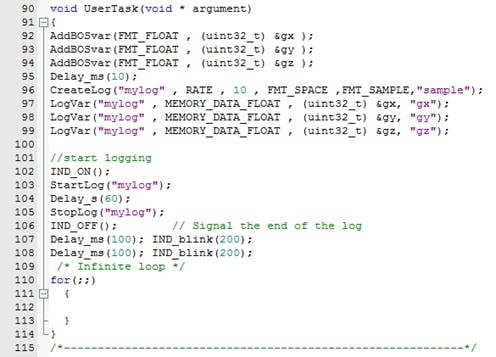
· The IMU module give us angular rate measurements, gravity vector measurements and orientation. We send these data to the micro SD module by a memory write API in for loop.
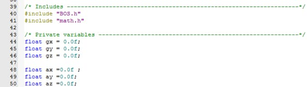
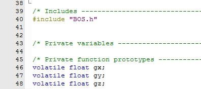
· First, we define float variables to storing the IMU measurements.
· BOS Variables can be addressed with easy-to-use virtual addresses. We can link a float sensor value to BOS Var 1 by AddBOSvar API and access it from micro SD module in the array.
AddBOSvar(FMT_FLOAT, (uint32_t) &gx );
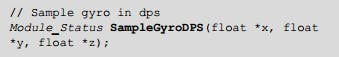
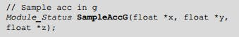
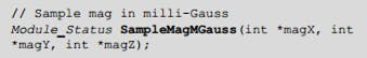
· Hexabitz IMU module supports sample readings of all sensors to an internal SRAM buffer, so we can use sample API to obtain gyroscope, accelerometer, or magnetometer data :
· In (H1BR6) module code: We define BOS IMU variables. Using the keyword volatile in front of a variable definition tells the compiler that this variable might change outside the program (by a remote IMU module).
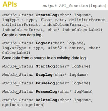
· Data Logs: micro SD memory card module H1BR60feature permanent logging functionality to a FAT-formatted micro-SD card.
· You can create up to 10 simultaneous logs with up to 30 different variables across all logs.
· Logs are tabulated text files that consist of a header section, a bunch of columns-each representing a single logged variable, and a bunch of rows-each representing the variables’ value at a given moment. Logs have two types: RATE and EVENT.
· The former type logs variable state periodically at a fixed rate, while the latter logs only a state change.
· We create below a rate-based log and log the sensor values.
· Logging is then started and stopped after 60 seconds. You can increase this time to logging more sensor data. The indicator LED is used to show some blinks!
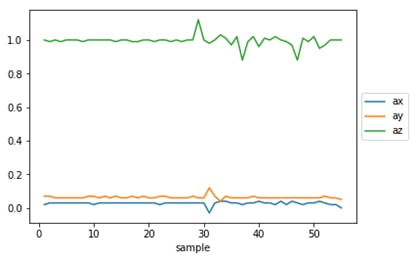
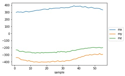
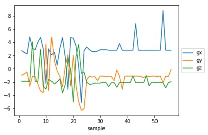
Result
2- Calibration of IMU Errors
Input values for any navigation algorithm are signals of gyroscopes and accelerometer. It is very important to know sources of IMU errors.
Errors in an IMU measurement can be broken down into three main categories:
1. Biases : IMU biases can be further broken down into three types:
- The Fixed Bias or Offset Biases that are deterministic in nature & can be calibrated out as see in figure. Fixed biases can create one of the largest errors in an IMU.
- Stability Bias change random from run to run of the IMU.
- Instability Bias change as a random process that is a function of time.
2. Scale Factor Errors
3. Misalignment Errors (Cross Coupling Errors)
The quality of IMU can be determined through two basic variables: bias, and white noise.
Sensors will have an offset (bias), which means at rest they will not read exactly zero – even though in theory they should. This can be mitigated by keeping the IMU at rest, summing the measurements over a period of time, and finally dividing by the total number of measurements. This final value – the average offset – can then be subtracted from all future readings to ensure that the actual measurement is close to zero when the system is at rest and level. The white noise can be measured in several ways like Allan variance
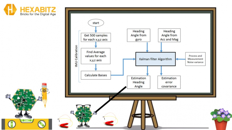
3- Sensors fusion algorithm and how to implement it
Filtering is about recursively estimating parameters of interest based on measurements, the Kalman filter is an optimal estimation algorithm within a wide range of linear system states, and we use to Estimate the state of the position of the mobile robot, by fusing measurements from gyroscope and accelerometer.
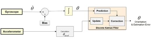
The Kalman filter consists of two stages. In the first stage, a mathematical state model is used to make a prediction about the system state. In the next stage, this state prediction is compared to measured state values.
The difference between the predicted and measured state is moderated based on estimated noise and error in the system and measurements, and a state estimation is output. The output estimation is then used with the mathematical state model to predict the future state during the next time update, and the cycle begins again.
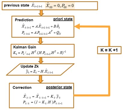
Measurements are given until k time
The following Figure shows an algorithm diagram.
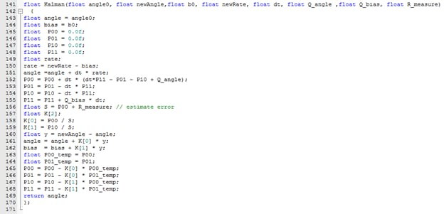
Implementing the filter with Keil uVision
You can use the free online calculator Wolfram Alpha to calculate the Kalman filter matrices for the c code.

We will use the Kalman filter equations to implement the filter into a simple c code that can be used for robots, wearables and other applications where you need to compute the correct angle.
4-Test Sensors fusion algorithm in 2D(Test1):
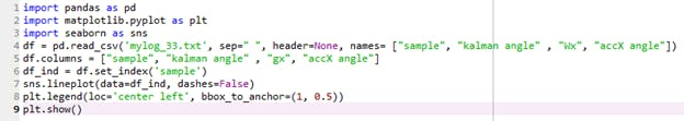
After .txt file created by uSD module, and the IMU data were wrote into it, we plot a graphs (with Spyder/python3.7).
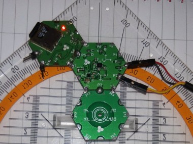
Add M2/M2.5/M3/M4 Mounting Hole Module (H00R1) to Hexabitz array and add a rotating axis. Now we have a platform to test the algorithm and verify its correctness.
Note:
When you need to represent something in 3D orientations, as Euler angles suffer sometimes from what is called Gimbal lock. Therefore, you will need to use Quaternions or another methods to do that.
5- A Fusion Method for Combining Low-Cost IMU/Magnetometer Outputs(Test2):
We present a fusion method for combining outputs acquired by Hexabitz Module(inertial measurement unit and electronic magnetic compass). Specifically, measurements of accelerometer and gyroscope sensors are combined with magnetometer sensor measurements to provide the optimal three-dimensional (3D) orientation of the sensor’ axis system in real time.
The method was implemented, debugged, and evaluated in Keil uVision5 software utility by using Hexabitz modules, and its efficiency was evaluated experimentally.
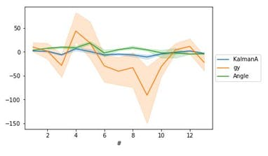
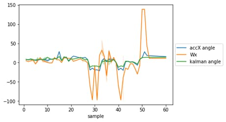
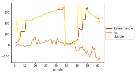
This figure shows one of the diagrams drawn from the results stored on sd module. Where we note that the steering angle resulting from the output of Our Kalman algorithm (the signal in red) eliminates the accumulated shift present in the angle signal calculated from the gyroscope sensor only (orange) and the noise as well as the noise in the angle signal calculated from the accelerometers and magnetometers (yellow color).
We have drawn a circular experiment path diagram of a circle with a radius of 6.5 cm where the following figures show the test method and results
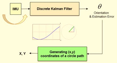
The path was determined based on the structure that was implemented, where the diameter of the circle can be changed by increasing Hexabitz modules used.
We plotted the system's moving path using the angles of the Cartesian projections of the circle Where the path coordinates computed according to the gyroscope sensor appear only (in green), the path coordinates calculated according to the accelerometer and the magnetometer (in blue), and the output coordinates of the designed algorithm (in purple), where we note that the resulting values are continuous and free of noise and shifts.

The method combines Euler angles and rotation matrix for attitude and heading representation estimation. The mathematical formulation of the method is based on Kalman filter.
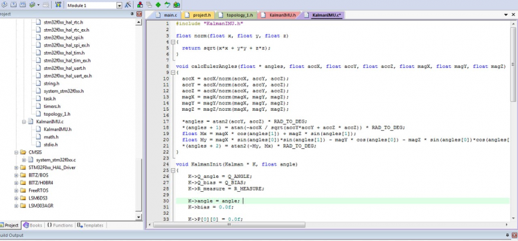
#include "KalmanIMU.h"
float norm(float x, float y, float z)
{	return sqrt(x*x + y*y + z*z);
}
void calcEulerAngles(float * angles, float accX, float accY, float accZ, float magX, float magY, float magZ)
{
	accX = accX/norm(accX, accY, accZ);
	accY = accX/norm(accX, accY, accZ);
	accZ = accX/norm(accX, accY, accZ);
  magX = magX/norm(magX, magY, magZ);
	magY = magY/norm(magX, magY, magZ);
	magZ = magZ/norm(magX, magY, magZ);

	*angles = atan2(accY, accZ) * RAD_TO_DEG;
	*(angles + 1) = atan(-accX / sqrt(accY*accY + accZ * accZ)) * RAD_TO_DEG;
	float Mx = magX * cos(angles[1]) + magZ * sin(angles[1]);
	float My = magX * sin(angles[0])*sin(angles[1]) - magY * cos(angles[0]) - magZ * sin(angles[0])*cos(angles[1]);
	*(angles + 2) = atan2(-My, Mx) * RAD_TO_DEG;
}
void KalmanInit(Kalman * K, float angle)
{
    K->Q_angle = Q_ANGLE;
    K->Q_bias = Q_BIAS;
    K->R_measure = R_MEASURE;

    K->angle = angle;
    K->bias = 0.0f;
    K->P[0][0] = 0.0f;
    K->P[0][1] = 0.0f;
    K->P[1][0] = 0.0f;
	K->P[1][1] = 0.0f; }
void KalmanStep(Kalman * K, float newAngle, float newRate)
{		/* Step 1 */
	K->rate = newRate - K->bias;
	K->angle += dt * K->rate;
		/* Step 2 */
	K->P[0][0] += dt * (dt*K->P[1][1] - K->P[0][1] - K->P[1][0]) + K->Q_angle;
	K->P[0][1] -= dt * K->P[1][1];
	K->P[1][0] -= dt * K->P[1][1];
	K->P[1][1] += K->Q_bias;
	// Discrete Kalman filter measurement update equations
	// Calculate Kalman gain
	/* Step 4 */
	float S = K->P[0][0] + K->R_measure; // Estimate error
	/* Step 5 */
	float G[2]; // Kalman gain
	G[0] = K->P[0][0] / S;
	G[1] = K->P[1][0] / S;
	// Calculate angle and bias - Update estimate with measurement zk (newAngle)
	/* Step 3 */
	float y = newAngle - K->angle; // Angle difference
	/* Step 6 */
	K->angle += G[0] * y;
	K->bias += G[1] * y;
	// Calculate estimation error covariance - Update the error covariance
	/* Step 7 */
	float P00_temp = K->P[0][0];
	float P01_temp = K->P[0][1];
	K->P[0][0] -= G[0] * P00_temp;
	K->P[0][1] -= G[0] * P01_temp;
	K->P[1][0] -= G[1] * P00_temp;
	K->P[1][1] -= G[1] * P01_temp;
}
References:
https://www.hackster.io/Asaadk/compact-multi-switch-data-logger-f769a5
Schematics, diagrams and documents
Code
Credits

Related products

Leave your feedback...