Cellular Bilge Alarm Monitoring (with Blues)
About the project
Remotely track of your boat's bilge alarm using Blues' Cellular Notecard to ensure that its not leaking or flooding.
Project info
Difficulty: Moderate
Platforms: Twilio, Blues Wireless
Estimated time: 1 hour
License: MIT license (MIT)
Items used in this project
Hardware components
Story
It's common for sailing boats to be left unattended for many months of the year, particularly when the weather starts to get colder. This is the most dangerous time for a boat to be in the water, especially if the boat is moored in a river or away from a marina! While many boats will have automatic pump systems in their bilge (lowest point for water to collect) to disperse any water they accumulate, whether that's from a leak or simply rain but there are limited mechanisms in place if the pump were to fail. That's where the Blues Notecard comes to the rescue, providing affordable, easy to use, cellular connectivity for your boat.
https://www.amusingplanet.com/2010/04/fantastic-sinking-boat-by-julien.html

https://www.amusingplanet.com/2010/04/fantastic-sinking-boat-by-julien.html
This project will walk you through wiring a water-activated float switch into your boat's bilge, using the Blues Notecard and Notecarrier F to build a battery backed up system to keep an eye on your boat while you're away from it.
Connecting to the Boat's SystemsMost boats will use some form of battery (Lead acid, AGM or lithium ion most commonly) and will run at common voltages of 12V, 24V or 48V. This makes it a little challenging connecting it to a microcontroller as typically GPIO is only rated for 3.3V or 5V input. We also don't want to heavily modify the existing system as it's already doing it's job keeping the boat afloat.
Example wiring from my boat's bilge

Example wiring from my boat's bilge
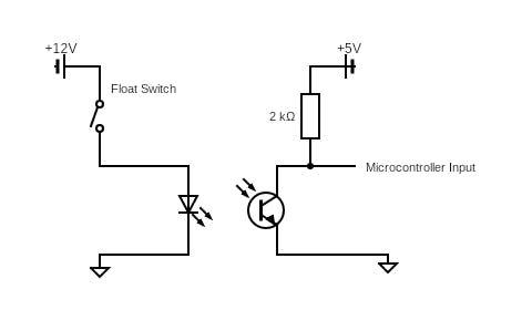
We'll use an optocoupler which is a voltage isolating IC designed to signal from a high voltage to a low voltage system without the risk of damaging the low voltage system. It works by using a light emitting diode inside of the IC package, which is powered on when current flows on the high voltage side. This then activates a phototransistor on the low voltage side, allowing current to flow. The diagram below shows roughly what the circuit might look like.
A rough visualisation of a optocoupler

A rough visualisation of a optocoupler
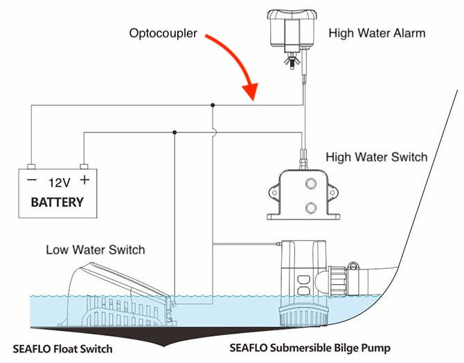
The diagram below shows a common alarm / pump circuit for a boat. The low water switch will run if any water accumulates, this is normal and can be expected to run intermittently if there is heavy rain and is no cause for concern. We want to place our optocoupler in series with the HighWater Alarm as this will indicate to us if the pump has been unable to keep up with the incoming water!
https://seaflomarinerv.com/index.php?m=home&c=View&a=index&aid=586

https://seaflomarinerv.com/index.php?m=home&c=View&a=index&aid=586
We'll use a standard PC817 Optocoupler breakout board to connect to our boat's 12V system in series with the high water alarm, i.e. if the High Water Alarm turns on, we want to know!
While the optocoupler can take 12V, the Blues Notecarrier F is limited to 5.5V so in this project, we'll connect up an external LiPo battery but in theory you can use a buck converter to drop your boat's 12V battery down to 5V. These are readily available on amazon or ebay as the are commonly used as phone chargers in cars.
We can now use the 12V alarm circuit to trigger an input on a 3.3V microcontroller; we'll connect this to a digital input on our Blues Notecarrier F development board.
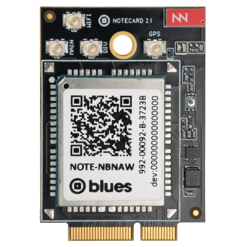
Blues Cellular ConnectivityThe Notecarrier F is a feather compatible baseboard for the Blues Notecard and Blues Swan (although you can use other feather boards!).
The Blues Notecard Cell is a great choice for a connectivity project like this as it makes it incredibly simple to send a JSON payload to the cloud. Before Blues, you'd have to fight against the pains of trying to save power, bandwidth and data when working with cellular modems. No more trying to remember which AT commands you need, you can simply throw JSON data at the Notecard over I2C or Serial and it takes care of the rest. You don't even have to worry about monthly subscriptions or SIM fees!
https://blues.com/notecard-cell-wifi/

https://blues.com/notecard-cell-wifi/
In our example, we'll create a simple payload structure to hold the state of the alarm, which will be binary, 0 for ok and 1 for alarm.
{"req":"note.add","body":{"ALARM":1},"sync":true}We use the sync key to tell the Notecard to immediately sync (transmit) to Notehub where we can access our data. Next, we'll need to instruct our microcontroller how to send this payload. We'll do this using the Zephyr RTOS project.
Installing and Setting Up the ProjectYou'll need a working Zephyr environment as this project uses the west tool to setup and initialise the environment.
west init -m https://github.com/bucknalla/blues-bilge-alarm --mr main my-workspace
cd my-workspace
west update
You'll also want to make sure you have the correct tools to flash the Swan board, either using an STLINK V2/V3 debugger or using the Swan board's DFU flashing.
To build and flash the project:
west build -b swan_r5 blues-bilge-alarm/app
west flash
Next we'll jump into a quick overview of what's going on in the project.
The Zephyr CodeNow that we have an alarm input and we've had a look at the Blues Notecard, we need to write some code to tell the Notecard if we have an emergency. For this tutorial, we'll be using the Zephyr RTOS project, a real time operating system for connected, resource-constrained and embedded devices supporting multiple architectures. Zephyr makes it easy to deploy across different hardware platforms, allowing you to use almost any microcontroller of your choice, without changing any code!
https://percepio.com/percepio-joins-the-zephyr-project/

https://percepio.com/percepio-joins-the-zephyr-project/
Our example runs on Blues Swan Development Board (STM32L4) but it could run on an ESP32 or a NRF52, for example. The steps below, walk through the logic running on the microcontroller to determine what it should do:
1. Initialise all of the peripheral devices, including 2 GPIO pins (one for the alarm and another for the LED), the I2C bus to communicate with the Notecard.
ret = gpio_is_ready_dt(&alarm);
if (ret < 0) {
    LOG_ERR("Failed to init Alarm.");
    return ret;
}

ret = gpio_is_ready_dt(&led);
if (ret < 0) {
    LOG_ERR("Failed to init LED.");
    return ret;
}
2. Establish the initial setup for the Notecard to communicate with Notehub. This required setting the PRODUCT_UID and establishing the serial number of the device, e.g. bilge-alarm.
J *req = NoteNewRequest("hub.set");
if (req) {
    JAddStringToObject(req, "product", PRODUCT_UID);
    JAddStringToObject(req, "mode", "minimum");
    JAddStringToObject(req, "sn", "bilge-alarm");
    if (!NoteRequest(req)) {
        LOG_ERR("Failed to configure Notecard.");
        return -1;
    }
} else {
    LOG_ERR("Failed to allocate memory.");
    return -1;
}
3. Configure the GPIO for the Alarm input and the LED output as well as set the callbacks to be triggered when the state of the Alarm input changes. We'll set the alarm to trigger on GPIO_INT_EDGE_BOTH so the callback will trigger when the alarm is raised and when it returns to normal. We'll also use a small snippet of code to allow for mechanical debounce in the switch. This should account for any accidental triggers!
gpio_pin_interrupt_configure_dt(&alarm, GPIO_INT_EDGE_BOTH);

gpio_init_callback(&alarm_cb_data, alarm_callback, BIT(alarm.pin));
gpio_add_callback(alarm.port, &alarm_cb_data);
3a. While the alarm is in the default state, the microcontroller should suspend its thread and ideally enter into a low power state.
while (true) {
    k_sleep(K_FOREVER);
    ...
}
3b. When an alarm is raised, we should turn on the LED and tell the Notecard that we need to send a message including the payload value for ALARM. This carries the binary state of the Alarm GPIO input. We then set the sync variable to true, to tell the Notecard to immediately send this message to Notehub. We don't want to mess around if the Alarm is going off!
int send_notecard_request(uint8_t state)
{
    LOG_INF("Sending notecard request...");
    J *req = NoteNewRequest("note.add");
    if (req) {
        JAddBoolToObject(req, "sync", true);
        J *body = JAddObjectToObject(req, "body");
        JAddIntToObject(body, "ALARM", state);
        if (!NoteRequest(req)) {
            LOG_ERR("Failed to submit Note to Notecard.");
            return -1;
        } else {
            return 0;
    }
    } else {
        LOG_ERR("Failed to allocate memory.");
        return -1;
    }
}
4. After sending our message, the microcontroller return to a low power idle state.
An in-depth dive into the source code would be too long for this project, however the source is documented and openly available on GitHub to view, modify, re-use.
Receiving Our MessagesGreat, now we have the ability to send messages to from our device to Notehub using the Notecard. Next we need to understand what to do once we have our data in the cloud; we need to forward it somewhere useful to alert us.
The Notehub cloud platform provides a number of routes you can use to do this. For example, you could use Twilio, an easy to setup SMS forwarding service, to receive alerts on your mobile phone.
https://www.logo.wine/logo/Twilio

https://www.logo.wine/logo/Twilio
Blues already has an excellent guide for how to set up Twilio routes in their docs; check that out for how to setup forwarding to your mobile device!
Are We Sailing Yet? (Wishlist Features)Great, we have a remotely connected alarm for the bilge switch now! But what happens when you want to go out sailing? You don't want a hundred alarms about water in the bilge when that's expected to happen while sailing! We'd need to sense when the boat is in motion and adjust the sensor accordingly.
To take this project further, you could consider some of the features of the Notecard module to allow you to do the following:
- Use the built in GPS for geofencing; to tell when your boat leaves it's mooring or berth
- Make use of the internal accelerometer to see when the boat is underway and / or what the roll of the boat is; this is a good indicator if the boat could be a risk of sinking!
- Add a solar panel to the Blues Notecarrier F to charge the system's backup battery without using the boat's 12V bus; add further redundancy in case of a battery failure!
- Observe the power input to the Notecard and detect if the main power source (i.e. boat battery) has failed and if we are using the backup battery. Blues has a nice tutorial on how to do this!
- Consider using the Power Management library in Zephyr RTOS to save power when idling


Leave your feedback...