
J.a.r.v.i.s: Led's Can Hear You.

Made by navinreddy23 / Artificial intelligence / Automotive / Displays / Voice / IoT
About the project
The goal of the project is to create an intelligent system that recognizes and reacts to twelve keywords such as ON, OFF, etc. These keywords are transmitted from one device to another device over a CANopen network, where LED's respond to these keywords.
Project info
Difficulty: Difficult
Platforms: NXP, Eclipse IoT, Edge Impulse
Estimated time: 3 weeks
License: MIT license (MIT)
Items used in this project
Hardware components


Software apps and online services
Hand tools and fabrication machines
Story
J.A.R.V.I.S
The name Just a Rather Very Intelligent System (J.A.R.V.I.S) is from the movie Iron Man. In this movie J.A.R.V.I.S is used by Tony Stark as his intelligent voice assistant. JARVIS in this project is an Artificial Intelligence (AI) system that responds visually to a set of pre-trained audial keywords. With the advancement in the field of Machine Learning (ML), tiny devices such as microcontrollers are capable of running ML models. This field is now termed as tinyML. At the moment, there is a lot of cutting-edge research and development that is being done in this field. It is always exciting to participate in the latest tech-trend, is it not? This motivated me to build an application with the board provided for the NXP Hackathon 2021.
I came across the NXP Hackathon 2021 competion while browsing through the social media. At that time I was planning on experimenting with CANopen (Software stack). After taking a look at the two boards that were available as the base kits, I chose iMX.RT1020 as the development boards. The reason is that these boards have hardware capabilities to support a CAN (Controller Area Network). There are very few examples that demonstrate the use cases of CANopen stack. I thought it is a good idea to integrate CANopen with an Audio Classifier and build a solution around it.
What have I made?
I have designed a system that classifies keywords such as ON, OFF, LEFT, RIGHT etc. on one board and transmits it over CAN bus. The other board receives these messages and process it to represent it visually using the LED's on the PCA9957 Arduino shield. The figure below represents the overall system.
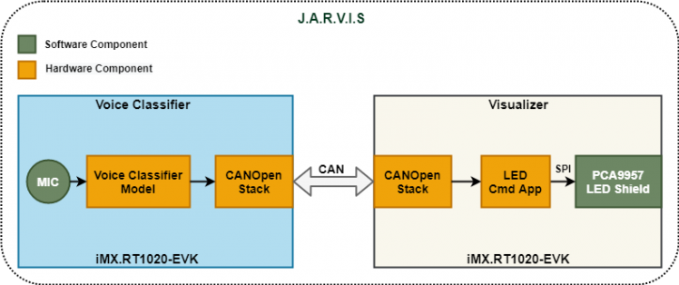
I have used two boards to develop the full application. At the system level one board acts as a Voice Classifier and the other one as a Visualizer. These two systems communicate with each other via the CAN bus.
The tasks that are performed by the Voice Classifer are:
- Aquire Audio and Perform Classification.
- Act as a Manager in CANopen network.
The tasks that are performed by the Visualizer are:
- Act as a Slave in the CANopen network.
- Display the classifed audio data on the LED shield.
Checkout the videos demonstrating the working of this system! Also, there are videos that show the project setup and training the audio classifier in the upcoming sections.
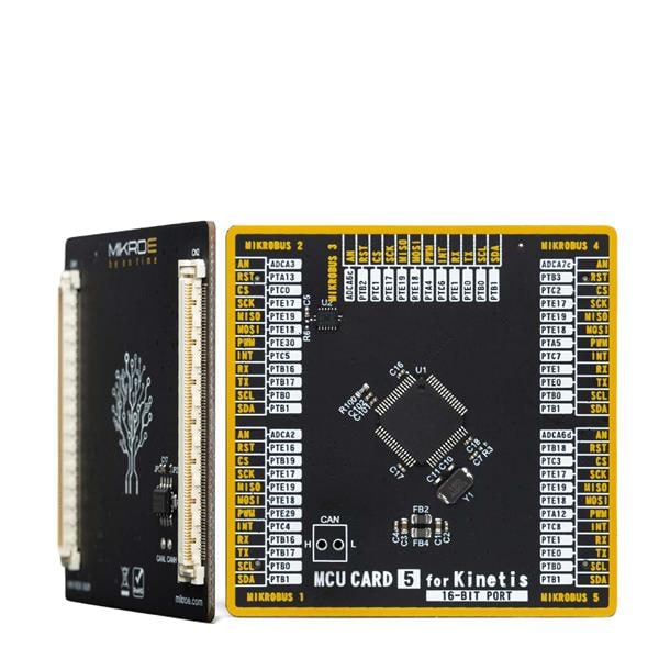
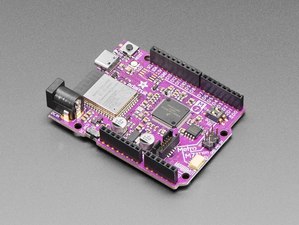
Hardware Features
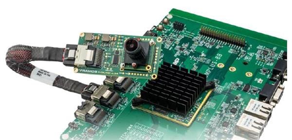
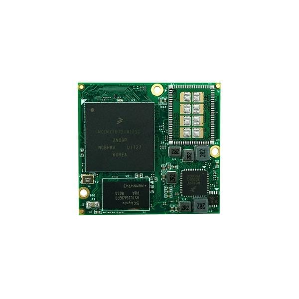
The board used in this project has the following key features:
- ARM Cortex-M7 High performance CPU
- Audio CODEC, Mic and a headphone jack.
- External SDRAM (256Mb)
- External 64Mb QSPI Flash.
- CAN, USB, SDIO, and Ethernet connectivity
Hardware Connections
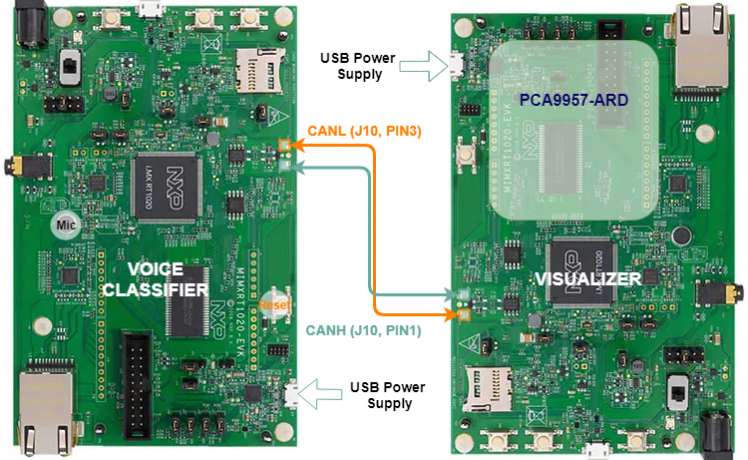
The two boards are connected to each other via CAN bus using the female-to-female jumper wires. The connections are as shown in the figure below. On the board, CAN transceiver pins are present on the J10 connector. Pin 1 of the J10 connector is a CAN High (CANH) and Pin3 is a CAN Low (CANL) line. These lines are connected such that CANH of one board is connected CANH of another board.Similarly, CANL is connected from one board to another board's CANL. Pin 2 of the J10 header is the ground pin. This pin should be connected (Pin 2 to Pin 2), if the power is not supplied from the same source.
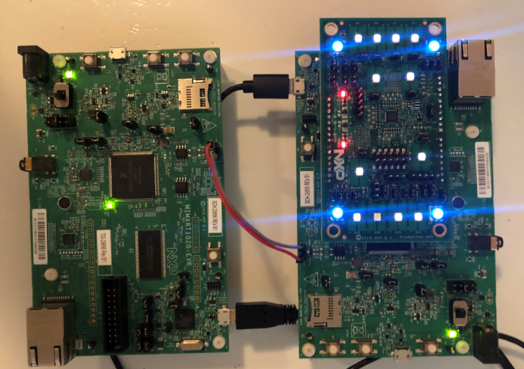
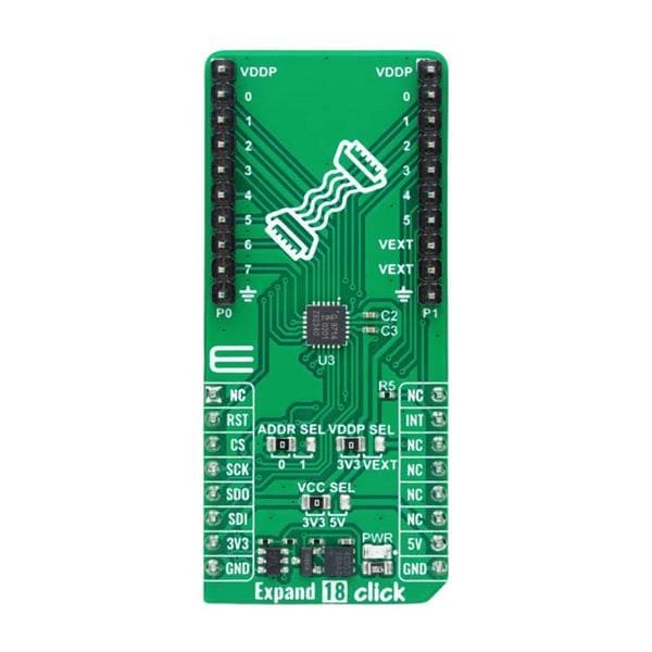
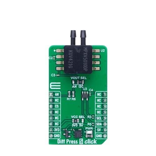
The PCA9957-ARD shield uses Serial Peripheral Interface (SPI) bus to communicate with the main board. It is connected via the Arduino compatible headers. The boards by default do not have these connectors soldered. Therefore, it is necessary to solder the female headers to J17, J18, J19, and J20 connectors. The figure below shows the mounted PCA9957-ARD shield on iMX.RT1020 board.
Voice Classifer Model
The Voice Classifier system consists of a model that takes in the raw audio sample acquired through the mic and outputs one of the twelve keywords. If no keywords are spoken, then it is classified as Background.
This model is trained using Edge Impulse software service. Edge Impulse has several set of tools where one can perform the following tasks:
- Data Acquisition.
- Generate features.
- Train and Test a Neural Network.
- Perform Live Classification.
- Generate Source/Binary files (Deployment).
The model that is used in this project is shown in the figure below.
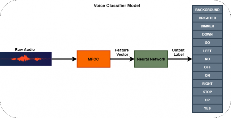
As seen in the above figure, the first step is to acquire the audio data. Following are the parameters used for voice/data acquistion:
- Audio length of 1 second.
- Sampled at 16000Hz
- Bit size is 16 bits (2 bytes).
Audio length is amount of time the device listens before processing the sample. Sampling frequency is the number of measurements pf amplitude performed per second. The bit size represents the number of quantization levels. For e.g. an 8-bit audio has 2^8=256 levels.
These parameters are sufficient for keyword spotting, but are not good enough for music playback! To learn more about digital audio basics, visit this link.
MFCC
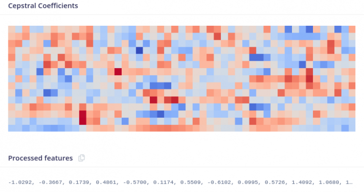
Moving on to the next block Mel Frequency Cepstral Coefficient (MFCC). This block takes raw signal as the input and transorms it into a vector/array. This process is called as Feature Extraction, and it is very important since the Neural Network learns from these features. The raw signal doesn't provide much information as it is, but when processed by the MFCC block, we get an array of numbers. This array represents significant information using which vowels can be identified. MFCC has number of stages before generating the feature vector such as Framing, Windowing, Fourier Transformation (FFT) etc. It is a complex process and I won't go into the mathematical aspects of this algorithm. To summarize, the raw audio signal is converted into a feature vector that is useful for training the neural network.
Figure below shows the features (Cepstral Coefficients) generated from a raw audio sample.
These Cepstral Coefficients are obtained by setting the parameters as shown in the figure below.

When it comes to providing a value for these parameters: there is no one exact or perfect value. For e.g. increasing the number of coefficients or the FFT length will in-turn increase the number of features generated. This will make the model more complex and will definitely take more processing time. On the other hand if the number of features are less, the Neural Network may fail to learn the differences between similar sounding keywords. This tradeoff should always be considered. This article describes the parameter setting for MFCC in detail.
Neural Network
Neural Network takes the input vector from MFCC and gives us an ouput predicting the accuracy of the provided audio data. This block is the last stage of the Voice Classifier Model.
A Neural Netowk (NN) is a mathematical model that tries to learn similarly to the human brain. Artificial neuron forms the basic component of this model which is derived from observing the biological neuron.
We have used a 1-D Convolutional Neural Network (CNN) as the learning model. CNN's have been successfully used for object classifcation such as handwritten digits (classic example!). The Cepstral Coefficients shown in the previous figure is also sort an image that can be fed into the CNN. Therefore, it is also possible for us to use the CNN for the Voice Classifier.
The figure below shows the CNN configuration used in the project.
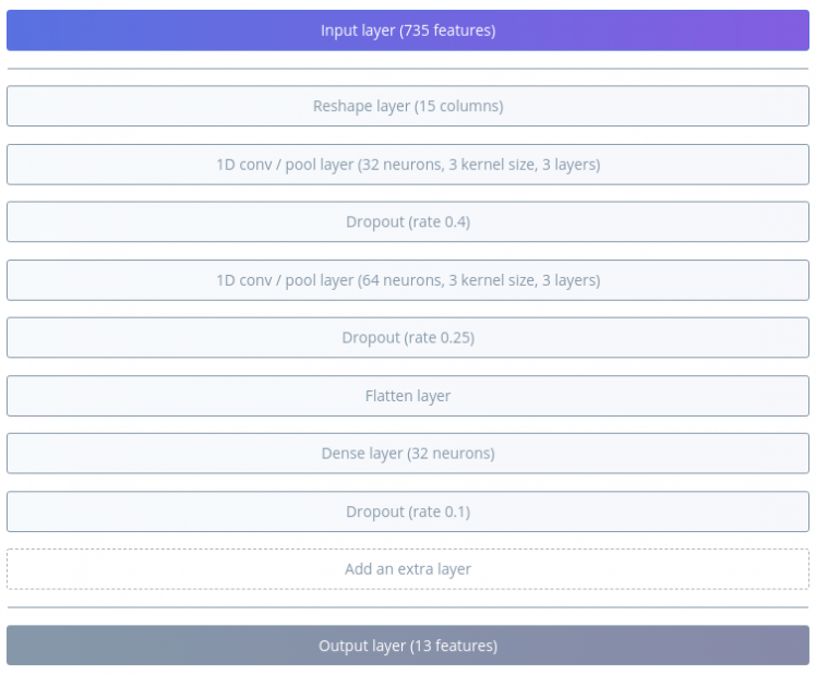
CNN has several layers such as Convolutional layer, Pooling, Dropout, Flatten etc. Each layer contributes to the learning process. This page provides relevant information regarding the CNN's for Speech Processing. It might be a good idea to learn a few basic concepts about NN's before starting to train the model. I suggest the reader to take a look at the link mentioned previously.
The number of neurons, layers, kernels and several other figures are termed as Hyperparameters. There is no perfect/exact value similar to the MFCC parameters. Tradeoff has to be made between the model's size and processing time. One can always experiment to acheive certain desired accuracy.
Using the settings above I have achieved a very high training accuracy for this model.
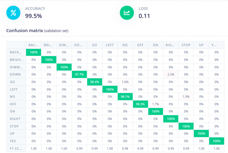
The accuracy of 99.5% is very high, it may be due to the less variation in the input data from the audio samples. Nevertheless, the model performs very well on the device. More on this is discussed in the results section.. A key point to remember while training a neural network is to have a balanced datset.
See the video below demonstrating Edge Impulse tool usage from acquring data to generating C++ code.
Project Related Tutorials
In this section I have added a few videos to show for e.g. how to add FreeRTOS to an existing project or configure SPI.
Prerequisties
- Install MCUXpresso IDE.
- Download and install SDK for evkmimxrt1020. The SDK can be built using the SDK Builder from NXP. Make sure to select MCO CANopen stack and other relevant examples as well.
- Install CANopen Architect mini, for generating CANopen source files.
Demo: How to add FreeRTOS to a Hello World project.
In this project we first import an Hello World example from the existing set of examples. To import a project from the SDK click on Import SDK example(s).. in the bottom left side of the MCUXpresso IDE. The rest of the tutorial can be seen in the video below.
Demo: Peripheral Driver Configuration using PCA9957.
This video shows how to add an SPI driver, which is needed to communicate with PCA9957-ARD shield.
Similar to this demo, other peripherals such as CAN, SAI, and I2S can be added.
Demo: Create C++ project and Configure Board SDRAM.
This demo shows how to create a C++ project and configure SDRAM. C++ project is necessary to work with the Edge Impulse sources because, they are mostly C++.
The Edge Impulse sources generated requires quite some heap memory. The default RAM is not sufficient if we have to use a large buffer to capture audio. Therefore, we need to use Board SDRAM (External to MCU) which is sufficiently large to hold all the global varaibles. We test the configuration by using a large buffer (for global variables) and C++ std::vector (heap test).More information on memory segmenation can be found in this link.
Demo: Import a project from GitHub to MCUXpresso IDE.
This video demonstrates on how to import a project from GitHub to MCUXpresso IDE.
Demo: Adding and configuring Edge Impulse SDK.
Edge Impulse SDK is externally generated. We need to include the headers and source files in our project.
In thisvideo, I will show how to add Edge Impulse SDK sources to MCUXpresso IDE. Configurating the project is not demonstrated, but the configurations that are already done is shown.
Configurations can be found in Project -> Properties.
Demo: Generate CANopen sources using CANopen Architect mini.
This is a short video demonstrating on how to export CANopen sources to MCUXpresso project.
More info on CANopen demo videos can be found in this link.
Software Design
The software design is analogous to the OSI model, implying that the hardware/board, software and application layer are decoupled from each other. This improves modularity and flexibility to the software development process. In the future, more number of features can be added easily with minimal modification to the existing software. For example, I have used the exact same Timer module on both the Voice Classifier and Visualizer. It is possible because it is independent of any functionality from the higher layers.
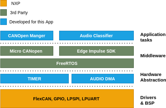
Overall architecture for the Voice Classifier is shown in the figure below.
The figure below is the representation os Visualizer's architecture.
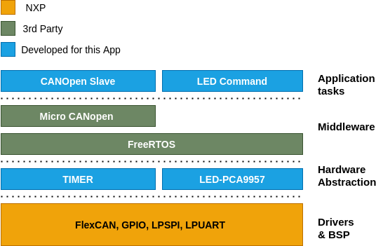
The Voice Classifier's and Visualizer's software architecture are divided into four layers.
- Drivers and Board Support Packages (BSP): This layer is provided by the hardware vendor in most cases. BSP is useful when different types of hardware and software are supposed to interact. For e.g. The IO pins for a button may be defined in the BSP. When a different Controller/Board is used, only the BSP needs to be adapted to get the button working again. Thereby, improving the portability.
- Hardware abstraction layer: The drivers provided by the vendor already provide a certain amount of abstraction. To further simplify the usage of the hardware drivers in the application layer, this extra abstraction is made.
- Middleware: This piece of software is mostly provided by a 3rd Party vendor. This layer acts as a translational layer between the hardware and the application in most cases. FreeRTOS is one such example, which is used as an operating system (OS) in this system.
- Application: It is the highest layer in the model, through which the user is able to interact with the system.
Brief introduction to CANopen
CANopen is a higher level protocol used in the automotive and industrial applications. The network layer uses CAN bus to communicate between multiple devices. A message sent from one device in a CAN bus is broadcast to all other devices. When a system has multiple devices/nodes it may become difficult to manage the communication. CANopen solves this issue by using concepts such as Electronic Data Sheets (EDS) and Object Dictionary (OD). CANopen is also responsible for managing the network (e.g. Resetting a device on certain error). This introductory article is a good start for learning about CANopen along with this video.
A simple analogy might help in understanding the benefit of using CANopen. Let's say a PC is connected to a cloud service for syncing the files. In this scenario, the CAN bus acts as WiFi/Ethernet providing network connection. Whenver a file is created/modifed it is immediately uploaded to the cloud. CANopen does the exact same thing, a sensor data that changes on one device is reflected in all other devices. In our scenario, we update the command/label and accuracy in the Voice Classifier and this information is available on the Visualizer.
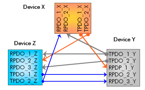
Process data object (PDO) is the process data (e.g. temperature value) that is available in real-time across the connected devices. Transmitting process data object (TPDO) can be linked to a Receiving process data object (RPDO) in the OD. So, any change in the TPDO is sent to the corresponding RPDO. The TPDO and RPDO used in this project will be explained later with the code.
Why use an OS and not just Bare Metal?
Bare Metal is type of software where there isn't scheduler to manage the processes. Simply, it is an operating system-less software. In a bare metal system, the lines of the code are executing sequentially. Usually, this type of approach is preferred on devices that have limited resources such as memory. As the application grows in complexity, the number of lines of code also increases. It then becomes easier to maintain the system when the software is broken down in to small tasks.
An Operating System (OS) is a software that performs task management, event management, memory management and message passing to name a few. Using an OS simplifies the complex interaction between the tasks/processes.
For example, in our system, the CANopen Manager and Audio Classifier tasks are running simultaneously. When the classifier produces an output it is sent to the CANopen process through an inter-process communication mechanism. This simplifies the code interpretation, which otherwise would have led to several if-else-for-while statements.
Application Tasks/Processes
In this section I will briefly explain the tasks, queues and notification used to manage and synchronize the events.
Below is the figure showing the interaction between various elements in Voice Classifier.
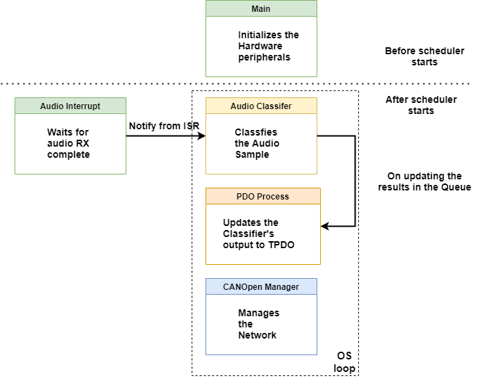
In the figure, the blocks enclosed in the dotted lines are the tasks.
The program flow is as follows:
- In the main function of the program, the hardware is setup, tasks are created and the OS is started.
- All the tasks are running simultaneously. The Audio Classifer task has nothing to do until an audio sample is ready. When the audio sample is acquired in the buffer an interrupt is generated. This interrupt notifies the task classifier to continue processing.
- The Audio Classifer task performs classification and inserts the result in a queue.
- The PDO process waits forever until there is an item in the queue. When the queue is not empty the results are updated in the TPDO.
- CANopen Manager task runs as a higher priority task taking care of the network. There is a small delay in this task that causes a switch. This is intended to share the CPU with other resources.
Below is the figure showing the interaction between various OS elements in Visualizer.
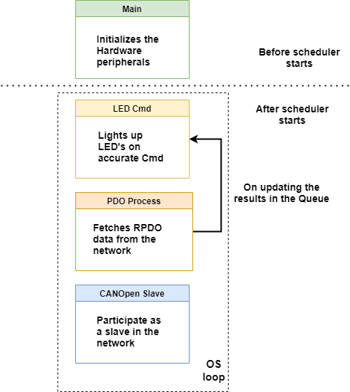
The program flow is similar to the previously mentioned Voice Classifier.
The only difference is the that the PDO process puts the results in the queue. And the LED Command (Cmd) process waits on the queue until a data item is availble in the queue.
Code Explained
In the next two sections the code (snippets) used in this projectwill be explained. If the comments in the code are not clear, then this section might help in understanding it better.
Voice Classifier Code
First let's look into the code of the Voice Classifier Project. The source files are located in ProjectName/source directory.
main.cpp
- /***
- * @brief Application entry point
- * Initialises HW and Application tasks and Starts the OS
- */
- int main(void)
- {
- InitializeHardware();
- PRINTF("Core Clock frequency: %u MHzrn", SystemCoreClock/1000/1000);
- PRINTF("rnInitialized hardware - AUDIO-DMA, CAN, TIMER, and UARTrn");
- //Create tasks and queues.
- CANOpen_Init(NULL);
- AUDIO_Classifier_Init(NULL);
- PRINTF("rnStarting OS...rn");
- vTaskStartScheduler();
- while(1);
- return 0;
- }
- /**
- * @brief Initialize all the peripherals that are necessary.
- * Baud rate for UART is set to 460800 bps.
- */
- static void InitializeHardware(void)
- {
- BOARD_ConfigMPU();
- BOARD_InitBootPins();
- BOARD_InitBootClocks();
- BOARD_InitBootPeripherals();
- BOARD_InitDebugConsole();
- LIBCB_InitLeds();
- AUDIO_DMA_Init();
- TIMER_Init();
- }
This is the entry point for the application. What does this piece of code do?
- The hardware is initialized i.e. the peripherals, clocks, processor related configurations are done here.
- We then initialize application specific properties for CANopen and Audio Classifier. These include task creation, queue creation and setting up callbacks.
- Start the FreeRTOS scheduler and let it manage the tasks and the interaction between them.
CANOpen.c
- /**
- * @brief Create two tasks and register a timer callback function.
- */
- void CANOpen_Init(void* arg)
- {
- xTaskCreate(TaskCANOpenManager, "CANOpen Manager", 512, NULL, HIGH_PRIORITY, NULL);
- xTaskCreate(TaskCANOpenProcessPDO, "CANOpen PDO Processor", 512, NULL, DEFAULT_PRIORITY, NULL);
- TIMER_SetCallBack(Tick);
- }
- /**
- * @brief This task waits on the queue until the results are updated
- * in the queue by the Audio Classifier task. These results are
- * updated in the CANopen network.
- */
- static void TaskCANOpenProcessPDO(void* arg)
- {
- results_classifier_t finalResult = {0};
- uint8_t label;
- uint8_t accuracy;
- for(;;)
- {
- //Queue receive (Blocks until the results are sent)
- xQueueReceive(qResults, &finalResult, portMAX_DELAY);
- label = finalResult.label;
- accuracy = finalResult.accuracy;
- //Write the command/label that was classified.
- MCO_WriteProcessData(P600001_VC_Command, 1, &(label));
- //Write the accuracy of the label.
- MCO_WriteProcessData(P600002_VC_Accuracy, 1, &(accuracy));
- }
- }
- /**
- * @brief Task to handle the CANopen network as a manager.
- */
- static void TaskCANOpenManager(void* arg)
- {
- uint8_t NMTReset = TRUE; // reset all slave nodes once
- uint16_t NMT_ResetDelay; // delay before resetting slave nodes
- NMTReset = TRUE;
- NMT_ResetDelay = MCOHW_GetTime() + 500;
- MCOUSER_ResetCommunication();
- for(;;)
- {
- // Operate on CANopen protocol stack, slave
- MCO_ProcessStack();
- // Application is processed in TaskCANOpenProcessPDO()
- //Process only when the state is operational.
- if (MY_NMT_STATE == NMTSTATE_OP)
- {
- MGR_ProcessMgr();
- USER_ProcessMgr();
- }
- if (NMTReset && MCOHW_IsTimeExpired(NMT_ResetDelay))
- {
- MGR_TransmitNMT(NMTMSG_RESETAPP, 0);
- NMTReset = FALSE; // only do it once
- }
- vTaskDelay(10);
- }
- }
- /**
- * @brief This function provides a periodic tick of 1ms to
- * the CANopen stack.
- */
- static void Tick(void)
- {
- MCOHW_Tick();
- }
- CANOpen_Init: In this function we create teo tasks, one for CANopen manager and the other for the PDO processing. The Manager task has higher priority, since it needs to handle the slave and perform several other operations frequently. In an RTOS system if a higher prioroty task and a lower priority task unblock at the same time then the higher priority task is scheduled first. After this we setup a callback function to provide a timebase to the CANopen stack.
- TaskCANOpenManager: Once the OS starts, this will be the first task to run. It will setup the CANopen stack and initiate communication between the slaves in the same CAN network. Notice that there is a small delay of 10ms in this task. It is neeeded to share the CPU between other tasks. Whenever a task is moved to a blocking state, it causes a context switch, which means other tasks which need CPU are scheduled next.
- TaskCANOpenProcessPDO: In this task we wait on the queue until we receive the processed results from Audio Classifier task. This will save the CPU processing time and reduces the load on CANopen stack. Once we receive the results, they are updated in the Object dictionary of CANopen stack. These to P600001_VC_Command & P600002_VC_Accuracy process variables will be updated with the label index and it's corresponding accuracy respectively.
- Tick: The timer module is setup to call this function every 1 millisecond.
audio_classifier.cpp
- /**
- * @brief Create Audio Classifier tasks and the result queue.
- */
- void AUDIO_Classifier_Init(void* arg)
- {
- xTaskCreate(TaskAudioClassifier, "Audio Classifier", 512, NULL, MEDIUM_PRIORITY, &hTaskClassifier
Code
Credits
Related products


Leave your feedback...