

Build An Automatic Toll Gate System Using Arduino

Made by electroscope_archive / Sensors
About the project
Hands-free toll gate using Arduino, RFID & IR sensors, detects vehicles, verifies payment, opens gate, and resets automatically for next use
Project info
Items used in this project

Story
This Automatic Toll Gate System Project Using Arduino demonstrates how to build a fully automated toll gate system using an Arduino Uno, RFID technology, IR sensors, and a servo motor to handle vehicle detection, payment processing, and gate control — all without manual intervention. It’s a hands-on, beginner-friendly project that mimics real-world toll operations and introduces you to integrating sensors, actuators, and identification systems with microcontrollers.
Build an Automatic Toll Gate System Using Arduino

Build an Automatic Toll Gate System Using Arduino
How It WorksThe system models an automatic toll collection setup:
- Vehicle Arrival – An IR sensor placed at the entrance detects the approach of a vehicle.
- RFID Authentication – When a vehicle stops, the driver presents an RFID card to the RC522 reader. The Arduino reads the unique ID and compares it to the stored values.
- Balance Verification – If the card is recognised and has sufficient balance, the toll amount is deducted. Otherwise, access is denied.
- Gate Control – On successful payment, a servo motor lifts the gate. A green LED indicates approval; a red LED shows denial.
- Exit Detection – A second IR sensor detects when the vehicle passes through, after which the gate closes, and the system resets for the next vehicle.
This workflow simulates a real toll booth where vehicles are automatically served as they arrive, reducing congestion and human effort.
Block Diagram
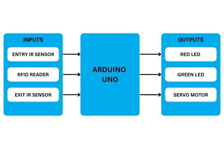
Block Diagram
Circuit Connections Summary- RFID Reader: SPI interface to Arduino digital pins.
- IR Sensors: Connected to digital input pins to sense approaching and exiting vehicles.
- Servo Motor: Connected to a PWM pin to rotate and open/close the gate.
- LEDs: Output pins to show system status.
Wiring the components correctly ensures reliable detection, authentication, and actuation.
Wiring Diagram

Wiring Diagram
Arduino Code EssentialsThe Arduino sketch integrates libraries like:
SPI.h— for communicating with the RFID module.MFRC522.h— for RFID operations.Servo.h— for controlling the gate motor.
The logic includes:
- Hardware initialisation and sensor setup.
- Continuous loop waiting for vehicle detection.
- RFID read and comparison with stored IDs.
- Balance check and gate actuation on success.
- Resetting LEDs and the gate for the next vehicle.
This structure teaches how to handle real-time inputs and outputs with a microcontroller.
Real-World ApplicationsBeyond toll booths, this system’s design can be adapted for:
- Parking lot automation (entry/exit control via cards).
- Residential or office access control systems.
- Industrial gates with secure vehicle authorisation.
- Smart campuses with automated vehicle tracking.
Once the core system works, you can enhance it with:
- LCD or OLED displays showing balance and status.
- IoT connectivity to log transactions and update balances online.
- Database integration to handle many users and dynamic pricing.
- Security upgrades like encryption or NFC support.
Schematics, diagrams and documents
Code
Credits
Related products


Leave your feedback...