
Build Diy Timelapse Camera With Unihiker K10

Made by rau7han / 3D Printing / Displays / Photos & Video / Wearables / IoT
About the project
In this guide, you’ll build a sleek, automated timelapse camera using the UNIHIKER K10 by DFRobot—perfect for capturing long-term scenes.
Project info
Items used in this project
Hardware components

Story
Timelapse photography is a great way to capture slow changes over time, such as plant growth, construction progress, or daily light changes.
In this project, I’ll show you how to build a DIY timelapse camera using UNIHIKER K10. This compact setup can automatically capture photos at fixed intervals and store them for later processing into a timelapse video.
I received the UNIHIKER K10 through the DFRobot Explore AI with K10 contest a few months ago, but only recently got time to work with it. I decided to start with a simple timelapse camera project.
This project is a good introduction to the UNIHIKER K10 and shows why it’s a useful board for many future projects.
Hardware:
1 / 3
- UNIHIKER K10 Board (DFROBOT)
- MicroSD Card (FAT32 formatted)
- USB-C Cable
Software:
- Arduino IDE (Version 2.0 or higher recommended)
- Libraries: TFT_eSPI (for the display) and the unihiker_k10 hardware support library.
(Optional)
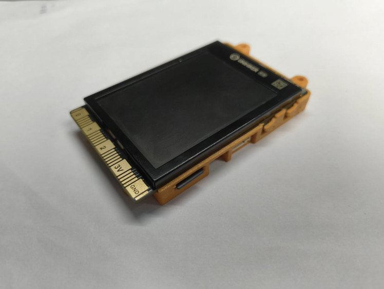
- Tripod or enclosure
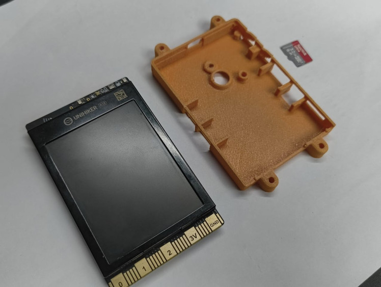
- 3D-printed case
Download the Case.stl file for 3D printing
Introduction to UNIHIKER K101 / 2
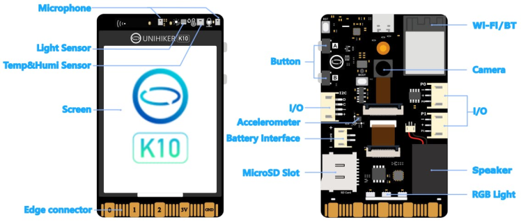
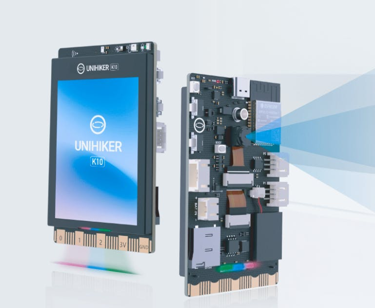
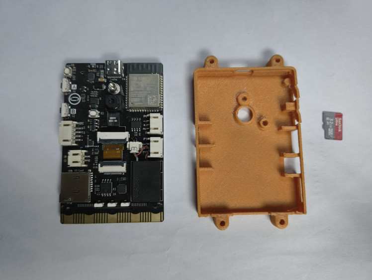
For this timelapse camera project, the UNIHIKER K10 is a solid choice because all the required hardware is already built into one board. A timelapse camera needs a camera module, a capable processor, basic controls, a display, and storage—and the K10 has everything.
The K10 is built around the ESP32-S3 Xtensa LX7chip and comes with:
- 16 MB flash memory
- 512 KB SRAM
- 2 MP camera
- 2.8-inch, 240×320 color display
- 2.4G Wi-Fi
- Bluetooth 5.0
- MicroSD card slot
- Support for multiple environments: Arduino IDE, Thonny IDE, PlatformIO, and Mind+
In short, it’s an all-in-one solution. Since no extra wiring or modules are needed, the setup stays simple and reliable, making the UNIHIKER K10 beginner-friendly and well suited for a DIY timelapse camera build.
Install the Unihiker K10 Board in Arduino IDE1 / 4

Before you begin, ensure you are using Arduino IDE version 2.3.7 or newer.
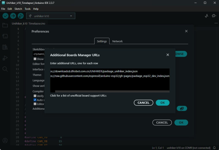
Open the Arduino IDE and go to File → Preferences. In the Additional Boards Manager URLs field, paste the following link:
https://downloadcd.dfrobot.com.cn/UNIHIKER/package_unihiker_index.jsonClick OK to save the settings.
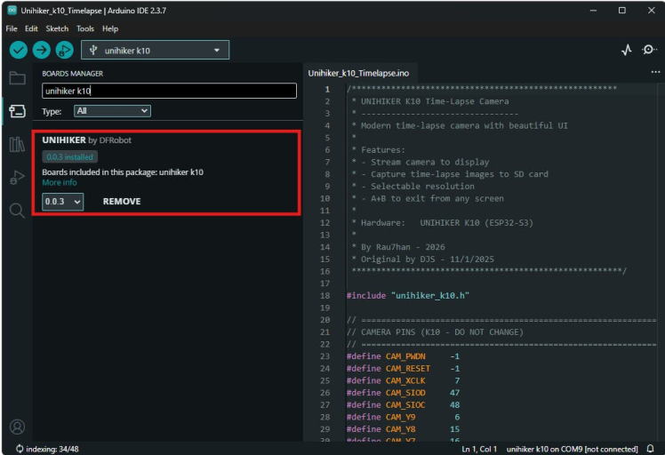
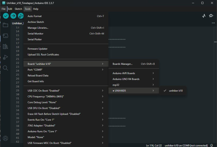
Next, navigate to Tools → Board → Boards Manager. In the search bar, type Unihiker and install the Unihiker board package.
After the installation is complete, go to Tools → Board and select Unihiker K10 from the list.
Once the board is installed and selected, the Arduino IDE is ready to upload code to the UNIHIKER K10.
Programming1 / 2

In this step, we upload the firmware that controls the timelapse camera. The code provides a simple on-screen menu to select camera mode, resolution, and capture interval. It also handles image capture, file naming, and saving photos to the microSD card automatically.
The complete code is provided in code block section for reference.
Note: The code is long because it includes a full UI, menu system, and recording logic.
After uploading the code, restart the board. You should see the menu appear on the screen, allowing you to start live preview or begin timelapse recording.
Testing and Demonstration
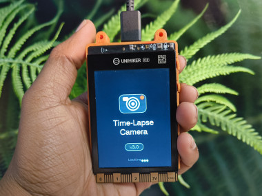
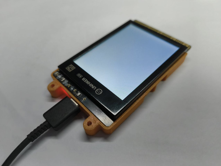
After uploading the code and powering on the UNIHIKER K10, the device starts with a custom splash screen showing a cute timelapse camera icon along with the app name and author. This confirms that the firmware has loaded correctly.
Once the splash screen finishes, the Mode Select menu appears on the display. Using Button A, you can switch between the two modes:
- Live Stream – shows a real-time camera preview on the screen
- Time-Lapse – captures images at fixed intervals and saves them to the microSD card
1 / 7
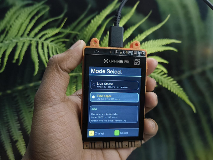
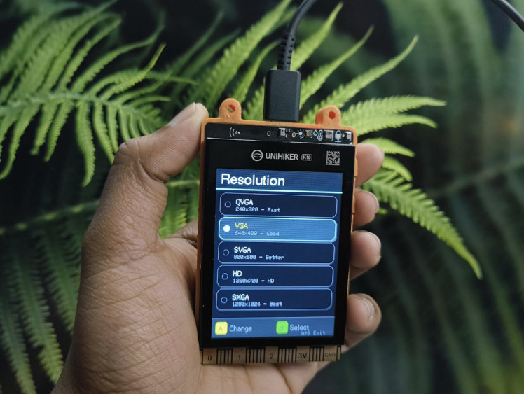
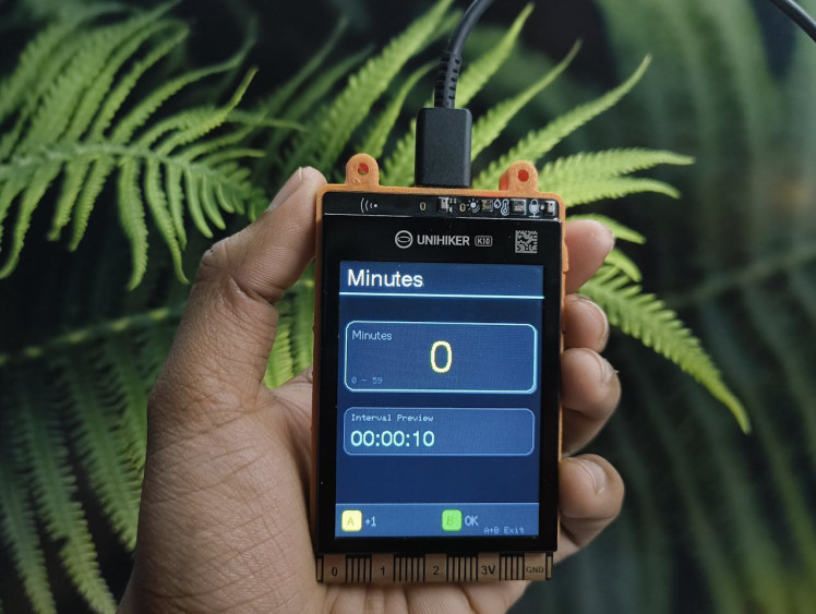
Press Button B to select a mode. In Time-Lapse mode, the screen guides you step by step to choose the image resolution.
Available image resolutions:
- QVGA (240×320) – Fast and stable (recommended)
- VGA (640×480) – Balanced quality
- SVGA (800×600) – Higher detail
- HD (1280×720) – High resolution
- SXGA (1280×1024) – Maximum quality
Note:
For long timelapse recordings, it is recommended to use lower resolutions like QVGA or VGA. Higher resolutions such as HD or SXGA can slow down capture, increase heat, and use more storage.
- Select Time-Lapse mode using Button B
- Choose the desired resolution
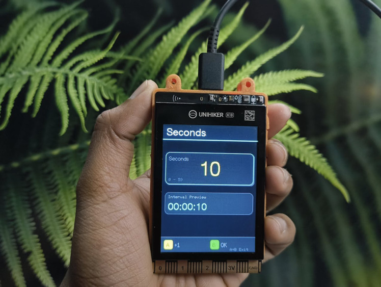
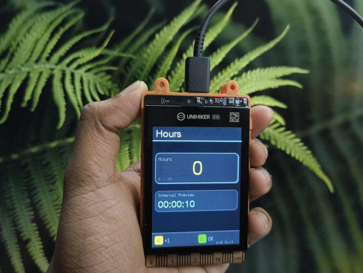
- Set the hours, minutes, and seconds for the capture interval
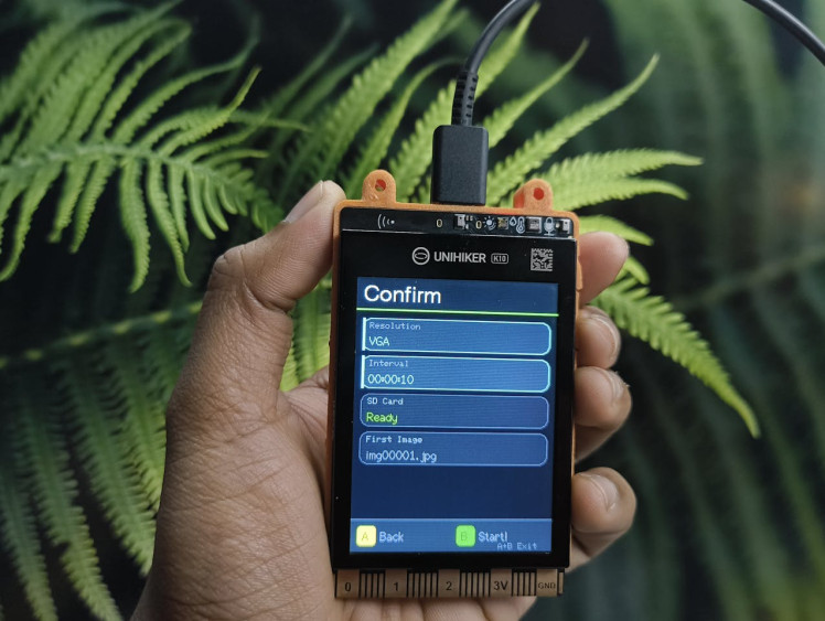
- Confirm the settings on the confirmation screen
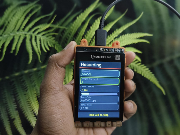
- Recording starts automatically
- Hold Button A + B together to stop recording safely
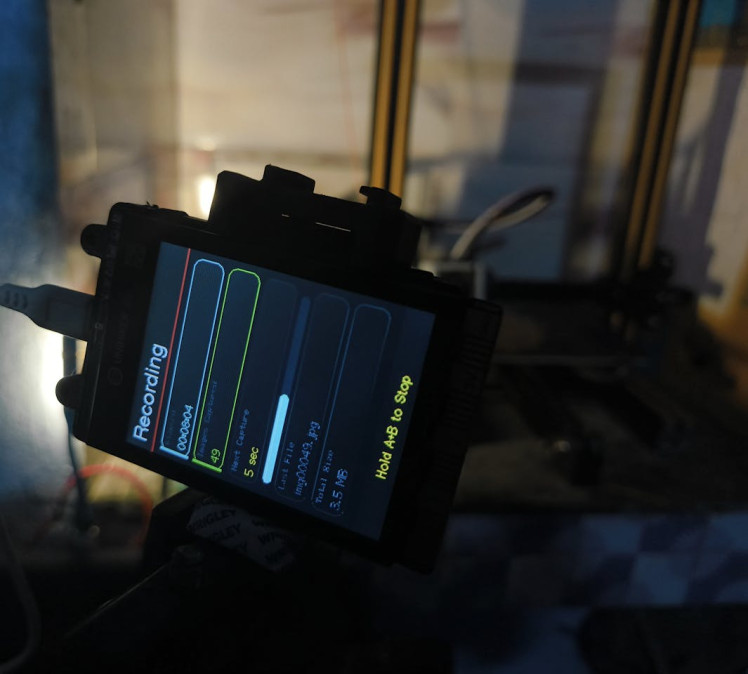
After testing the camera, I used it to record real timelapse videos in two different scenarios to demonstrate how it performs in practical use.
3D Printing Timelapse
The camera was placed facing a 3D printer bed to capture the printing process from start to finish. Using a short capture interval and a lower resolution helped keep the recording smooth and stable.
Schematics, diagrams and documents
CAD, enclosures and custom parts
Code
Credits
Related products


Leave your feedback...