
Braillebot

Made by mukesh-sankhla / 3D Printing / Health / Retro Tech / Robotics / Voice
About the project
Your very own Braille language trainer!
Items used in this project
Hardware components

|
Touch Sensor | x 1 | |
|
|
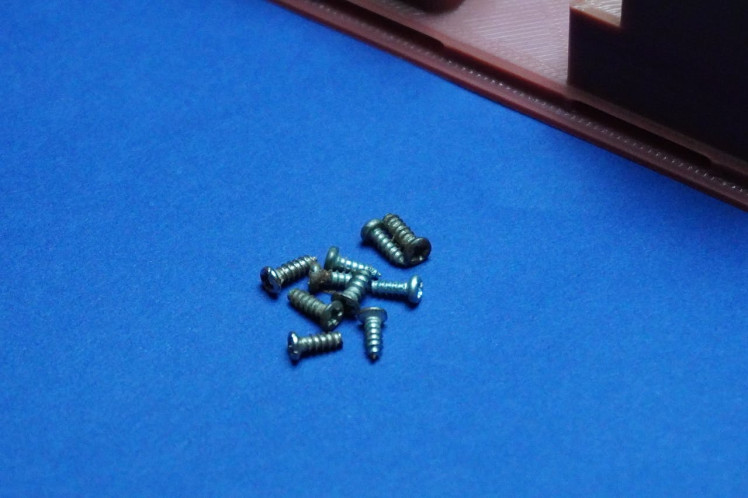
Screws | x 1 | |
|
|
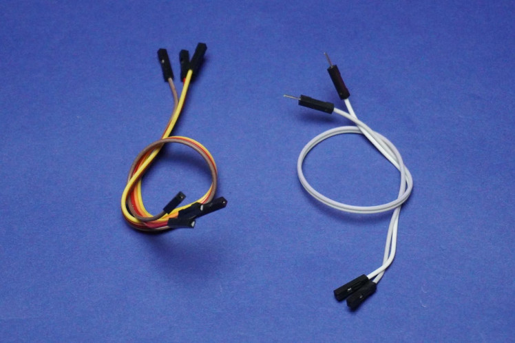
Jumper Wire Set | x 1 | |
|
|
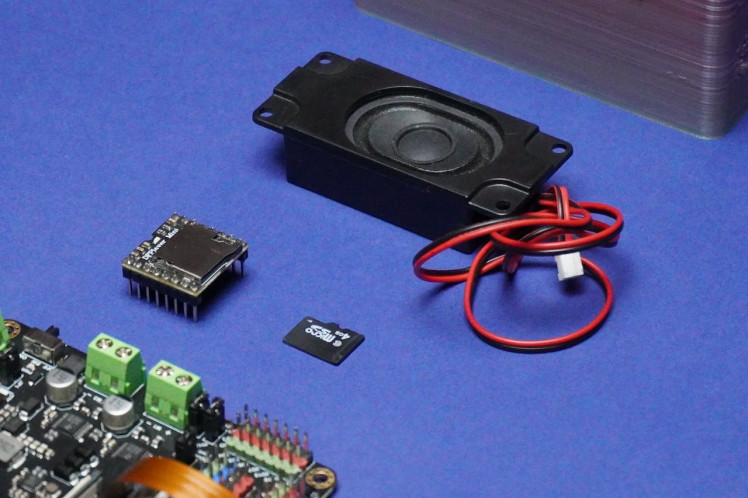
DFRobot Speaker | x 1 | |
|
|
Memory Card | x 1 | |
|
|
DFRobot DFPlayer - A Mini MP3 Player | x 1 | |
|
|
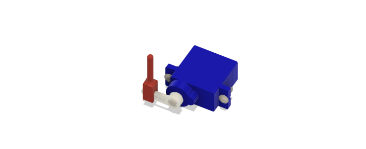
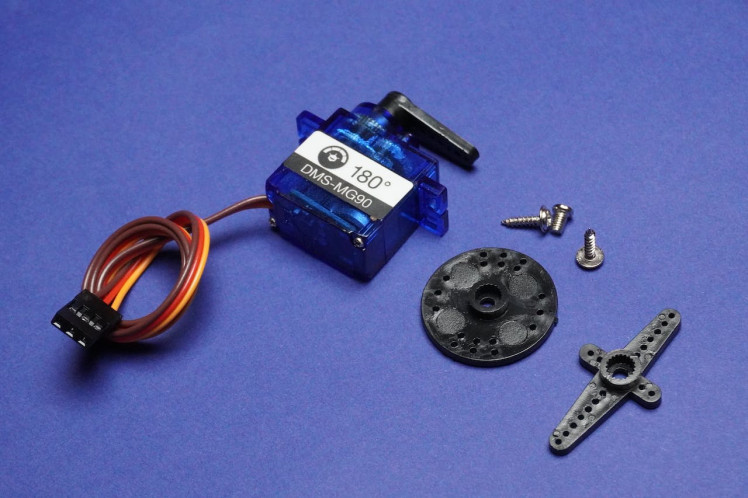
DFRobot Servo Motors | x 1 | |
|
|
DFRobot Romeo ESP32-S3 Development Board | x 1 |
View all
Story
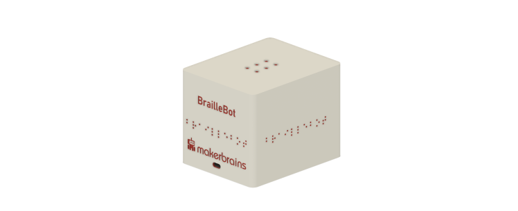
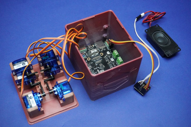
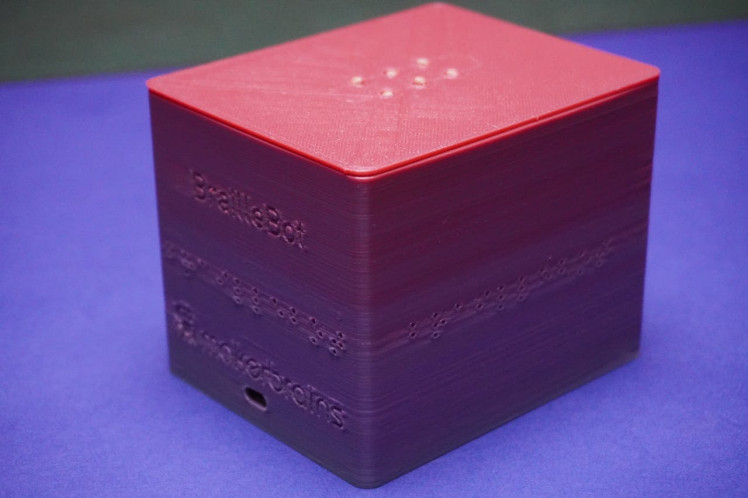
Imagine having a personal Braille tutor right at your fingertips! What makes BrailleBot even more amazing is that it won't break the bank—it's a budget-friendly option, coming in at just under $100. Now, let's dive into what BrailleBot is all about.
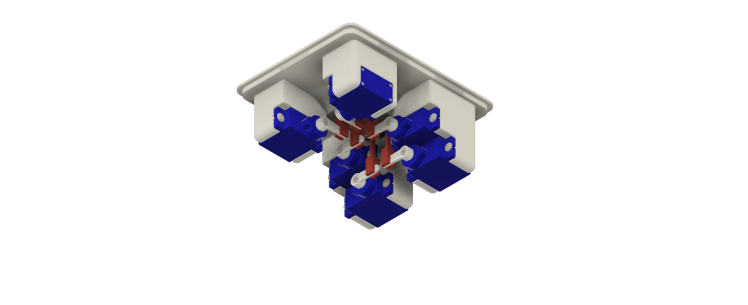
BrailleBot is a hands-on learning tool crafted to teach the Braille alphabet from A to Z. It's like having a playful friend that guides you through the world of Braille in an engaging way. The surface of BrailleBot is equipped with six dots, and each dot is controlled by a small servo motor. These dots create the tactile sensations that represent different letters in the Braille alphabet.
But wait, there's more! BrailleBot doesn't just stop at tactile learning—it also has an audio system. This means you not only feel the Braille dots but also hear the corresponding letters being vocalized. It's a multi-sensory experience, making the learning journey more enjoyable and effective.
Behind the scenes, BrailleBot is powered by the Romeo ESP32-S3 board, the brains that ensure everything runs smoothly and efficiently. So, whether you're a beginner trying to grasp the basics of Braille or a parent looking for an accessible and affordable learning tool for your visually impaired child, BrailleBot is here to open up a world of possibilities.
Get ready to embark on a Braille adventure with BrailleBot—where learning is hands-on, interactive, and loads of fun!
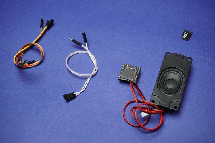
Supplies
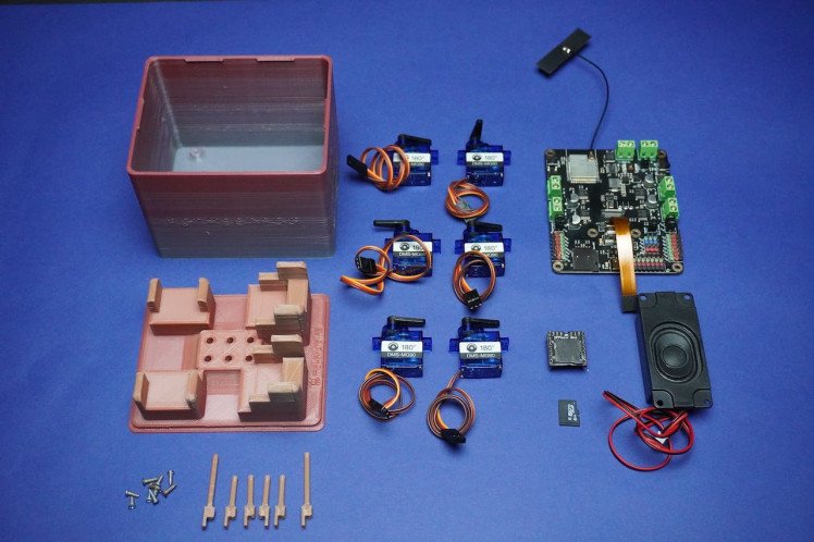

1x Romeo ESP32-S3 Development Board
6x Servo Motors
1x Memory Card
1x Speaker
1x Screws
2x Touch Sensor
My Equipment's:
Sponsored By NextPCB
This project is successfully completed because of the help and support from NextPCB -Reliable Multilayer PCB Manufacturer. NextPCB is one of the most experienced PCB manufacturers in Global, has specialized in the PCB and assembly industry for over 15 years.
Order high-quality, reliable PCB starting at $1.9, multilayer starting at $6.9:
https://www.nextpcb.com/pcb-quote
Enjoy free PCB assembly for 5 boards:
https://www.nextpcb.com/pcb-assembly-quote
DFM free online PCB Gerber viewer:
How BrailleBot Works?
1. Servo Motor Control:- Each of the 6 dots on the Braille surface is linked to a servo motor.
- When a specific alphabet is chosen for display, the corresponding servo motors rotate by a set degree, causing the connected dot to lift.
- The servo motors are programmed to lift the dots precisely, creating a tactile representation of Braille characters.
- This controlled movement ensures accurate positioning of the dots on the Braille surface, providing a clear and distinguishable touch experience.
- The control system of BrailleBot, powered by the Romeo ESP32-S3 board, determines which servo motors to activate based on the selected alphabet.
- For instance, to display the letter 'A, ' specific servo motors corresponding to the dots forming the letter 'A' are rotated.
- Simultaneously, the audio system connected to BrailleBot announces the selected alphabet.
- This audio feedback serves to reinforce the tactile learning experience, creating a multi-sensory approach to Braille education.
- The synchronization of tactile and auditory input enhances the user's understanding of the Braille characters and their pronunciation.
- BrailleBot incorporates two touch sensors, one on each side, allowing users to interact with the system.
- Users can navigate through the Braille alphabet using these touch sensors. One sensor may be designated for moving to the next alphabet, while the other is for moving to the previous one.
- This interactive feature promotes user engagement, making the learning process more dynamic and enjoyable.
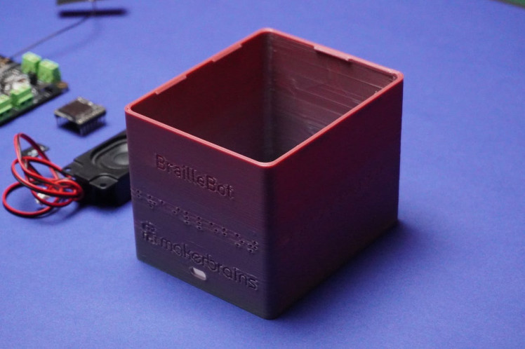
 Step 1: 3D Printing

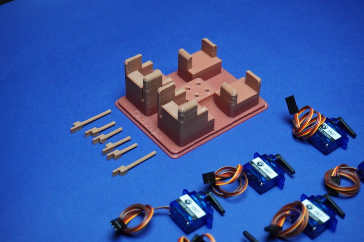
To bring your BrailleBot to life, let's start by 3D printing the essential components. Follow these steps to create the physical structure of your BrailleBot:
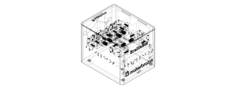
You can view BrailleBot design directly on your browser, download it, open it in Fusion 360 software and modify it according to your requirements.
Download all the provided 3D files (stl) and 3D print them.
I am using 2mm layer height and 100ms as speed On My Kobra Neo 2.
Parts:
1x Top.stl
1X Main.stl
4x Dot1.stl
2x Dot2.stl
Step 2: Small Adjustment
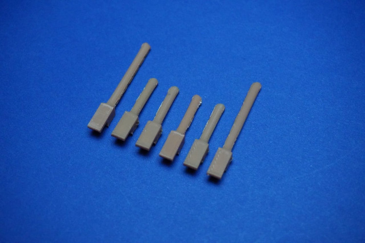
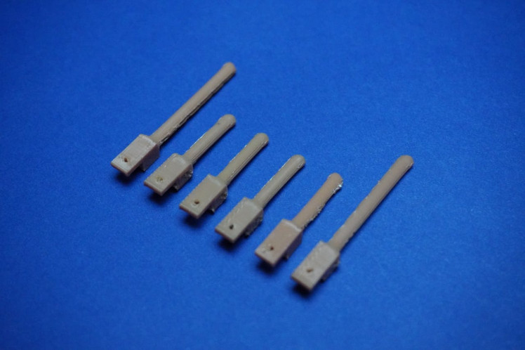
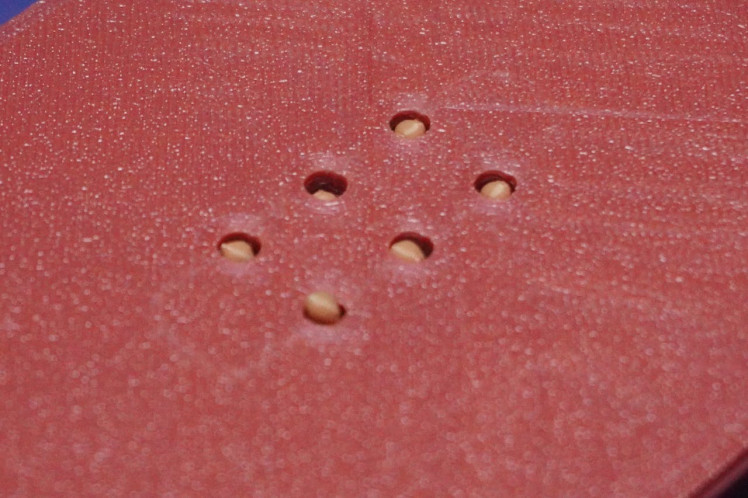
Minor adjustment needed in the Dots 3D design:
- Initially, I overlooked including holes to connect the dot pieces to servo motors. I have now revised the 3D model for you.
- However, be aware that these holes are quite small, and there's a possibility that the 3D printer might not capture them accurately.
- In such a case, you can use a small tool to manually create these holes on each dot piece.
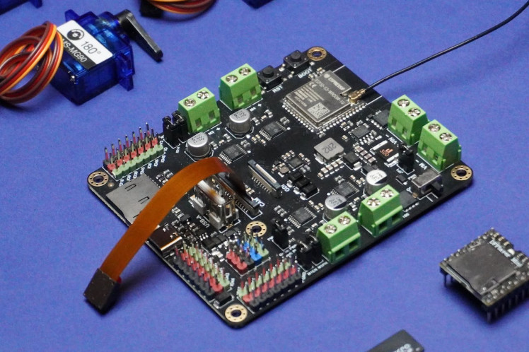
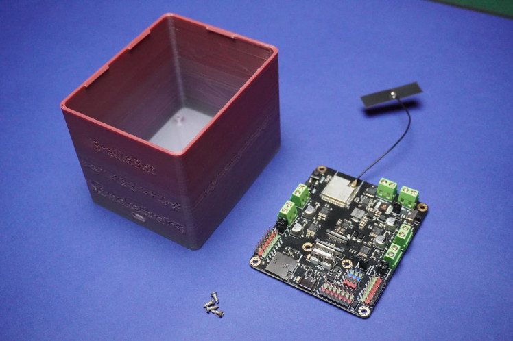
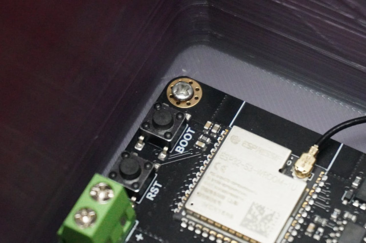
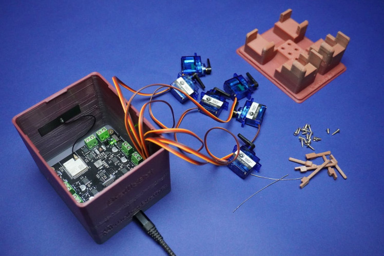
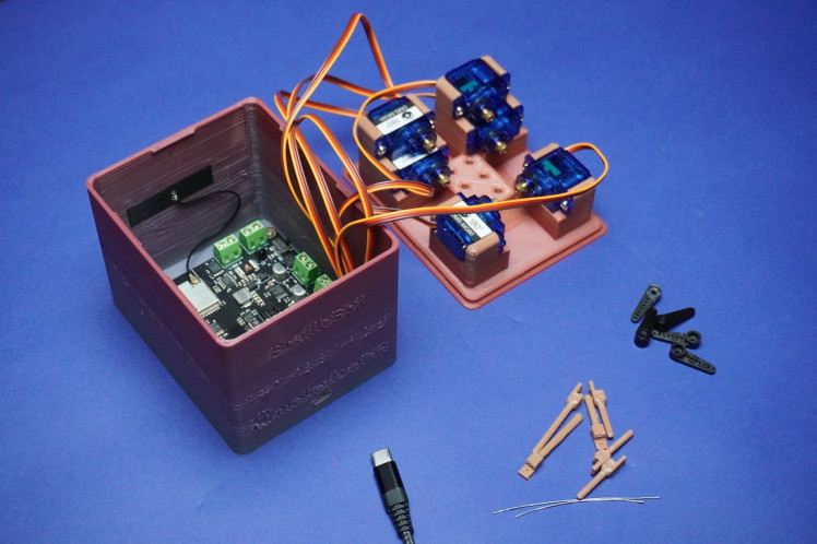
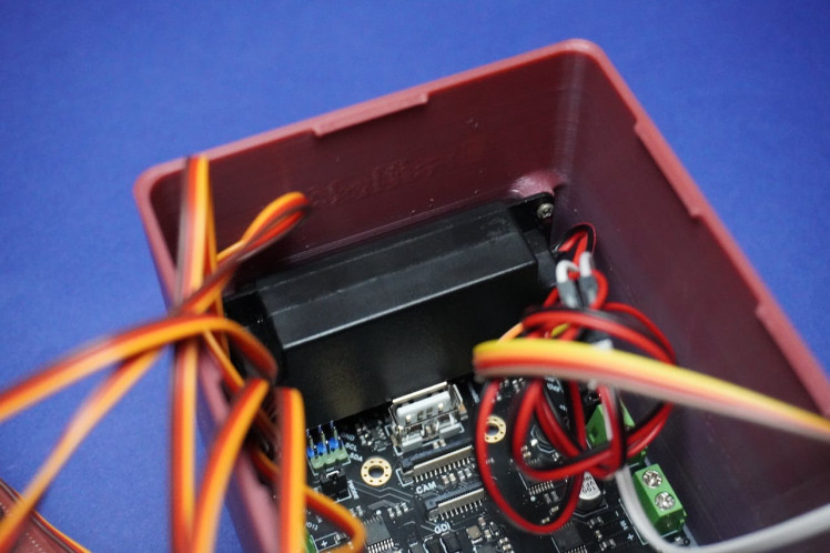
Step 3: Assembly 1
- Proceed by attaching the Romeo ESP32 board to the main 3D printed enclosure using 2mm screws.
- Align the Type C opening with the screw holes and carefully secure them in place.
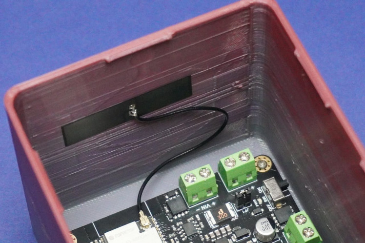
- Additionally, remove the antenna sticker and affix the ESP32 antenna onto the enclosure wall.
- Exercise caution during the screwing process to avoid potential damage to the electronics.
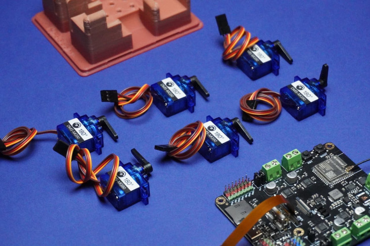
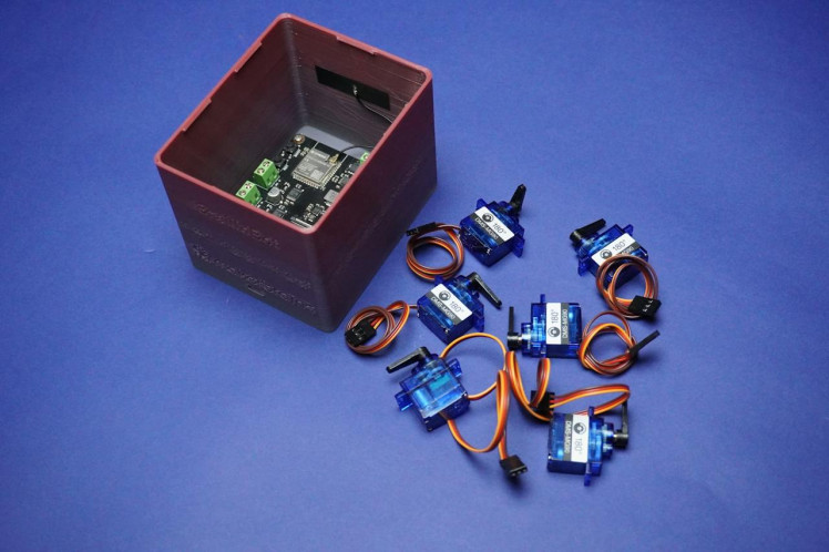
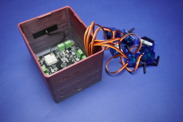
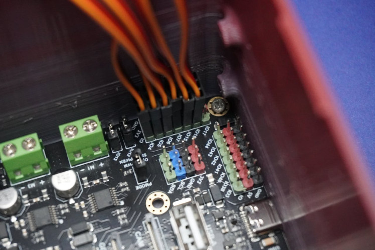
Step 4: Connecting Servo Motors
Connect the 6 servo motors by attaching their servo connectors to the following pins:
- 1st motor: IO4
- 2nd motor: IO5
- 3rd motor: IO6
- 4th motor: IO7
- 5th motor: IO15
- 6th motor: IO16
Ensure that the brown terminal of the connector is connected to the GND line, the red terminal is connected to 3V3, and the orange terminal is connected to the respective IO line, as illustrated in the provided image.
Step 5: Motor Initialization
To initialize the motors position, follow these steps:
- Ensure that you have the Arduino IDE installed with the latest ESP32 board manager.
- If you haven't installed the ESP32 board manager, you can follow the instructions in this link: Installing the ESP32 Board in Arduino IDE.
- Once the ESP32 board manager is installed, connect the Romeo ESP32-S3 to your PC using a Type-C cable.
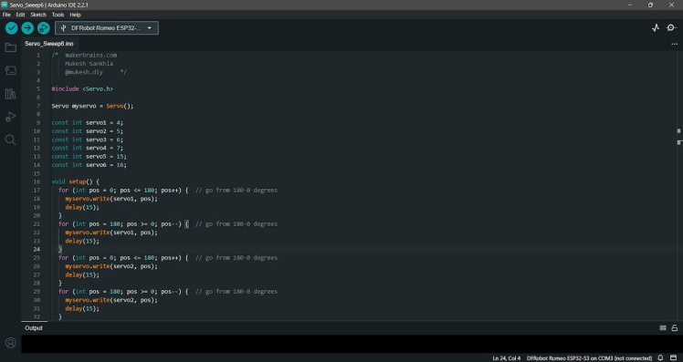
- Copy and paste the provided code below.
/*  makerbrains.com
    Mukesh Sankhla
    @mukesh.diy     */

#include <Servo.h>

Servo myservo = Servo();

const int servo1 = 4;
const int servo2 = 5;
const int servo3 = 6;
const int servo4 = 7;
const int servo5 = 15;
const int servo6 = 16;


void setup() {


  for (int pos = 180; pos >= 0; pos--) {  // go from 180-0 degrees
    myservo.write(servo1, pos);
    delay(15);
  }
  for (int pos = 0; pos <= 180; pos++) {  // go from 180-0 degrees
    myservo.write(servo1, pos);
    delay(15);
  }

  for (int pos = 0; pos <= 180; pos++) {  // go from 180-0 degrees
    myservo.write(servo2, pos);
    delay(15);
  }
  for (int pos = 180; pos >= 0; pos--) {  // go from 180-0 degrees
    myservo.write(servo2, pos);
    delay(15);
  }

  for (int pos = 180; pos >= 0; pos--) {  // go from 180-0 degrees
    myservo.write(servo3, pos);
    delay(15);
  }
  for (int pos = 0; pos <= 180; pos++) {  // go from 180-0 degrees
    myservo.write(servo3, pos);
    delay(15);
  }

  for (int pos = 0; pos <= 180; pos++) {  // go from 180-0 degrees
    myservo.write(servo4, pos);
    delay(15);
  }
  for (int pos = 180; pos >= 0; pos--) {  // go from 180-0 degrees
    myservo.write(servo4, pos);
    delay(15);
  }

  for (int pos = 180; pos >= 0; pos--) {  // go from 180-0 degrees
    myservo.write(servo5, pos);
    delay(15);
  }
  for (int pos = 0; pos <= 180; pos++) {  // go from 180-0 degrees
    myservo.write(servo5, pos);
    delay(15);
  }

  for (int pos = 0; pos <= 180; pos++) {  // go from 180-0 degrees
    myservo.write(servo6, pos);
    delay(15);
  }
  for (int pos = 180; pos >= 0; pos--) {  // go from 180-0 degrees
    myservo.write(servo6, pos);
    delay(15);
  }
}

void loop() {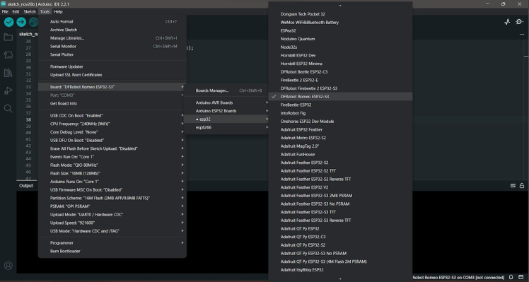
}- Select the Board type as "DFRobot Romeo ESP32-S3" in the Arduino IDE.
- Choose the correct port for your connected Romeo ESP32-S3.
- Upload the code to the board.
This code set the servos to the corresponding initial positions.
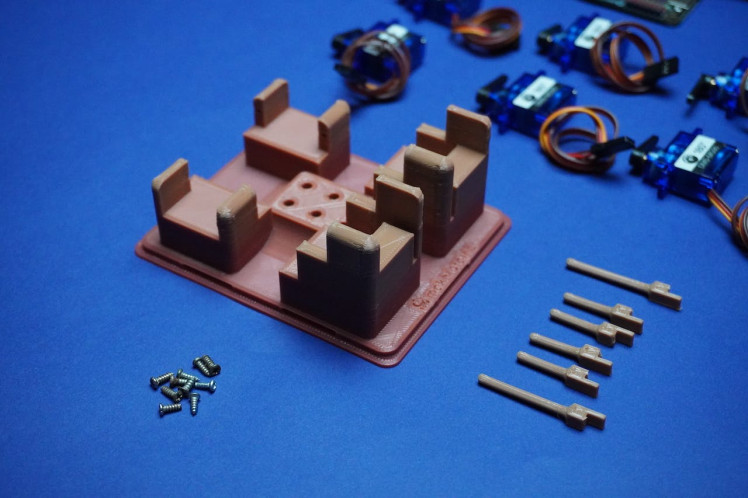
Step 6: Servo Motors Assembly
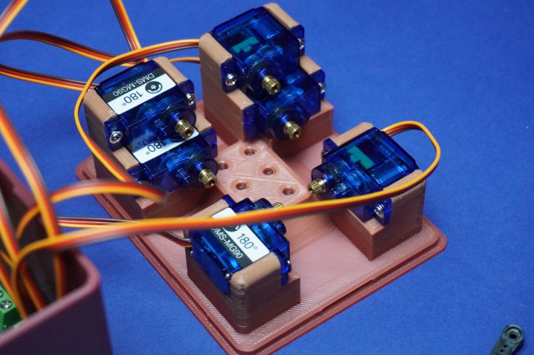

After completing the previous step, follow these instructions to assemble the servo motors into the Top 3D printed part:
- Begin by removing all the arms from the servo motors.
- Screw each servo motor into its corresponding position on the Top 3D printed part:
- Use the screws provided with the servo kit to secure each motor in place.
- Ensure the arrangement is as follows:
1, 2
3, 4
5, 6
Step 7: Dots Assembly
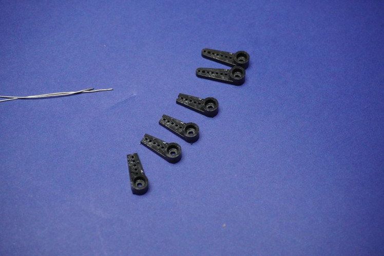
- First we have to cut 4 arm tips to adjust the arm length and avoid overlap.
- Plug the CType connector into your PC or any 5V power source, such as a power bank or a 5V adapter so that motors can initialize.
- Ensure that all arms are removed from the motors, as mentioned in the previous step, to prevent damage during initialization.
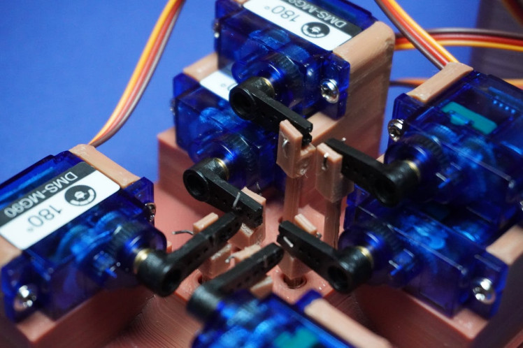
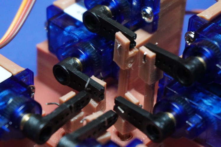
- With the system powered, carefully place all dot shafts according to their specified lengths.
- Connect each dot shaft to its corresponding arm and servo motor, using the single-strand wire as illustrated in the provided image.
- Be cautious during this step as the holes for assembly are tiny and may require precision.
- Take your time to ensure each dot shaft is securely connected to its designated arm and servo motor.
Step 8: Loading Voice
To incorporate voice functionality into BrailleBot, the DFPlayer Mini is utilized, which plays different audio files stored on a memory card in response to signals from the Romeo ESP32-S3.
- If you wish to use your own custom voice, you can explore https://speechgen.io/ for generating alphabet pronunciations.
- However, for immediate use, you can simply copy and paste the provided audio files from the GitHub repository: https://github.com/MukeshSankhla/BrailleBot.
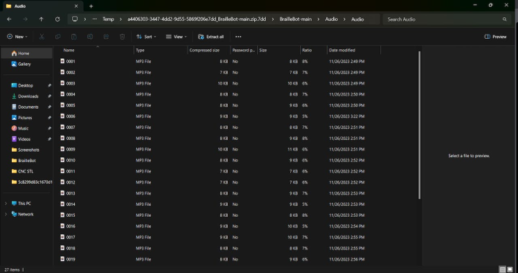
Follow these steps:
- Download the provided audio files from the GitHub repository by navigating to the repository and finding the "Audio.zip" file.
- Extract the contents of the "Audio.zip" file.
- Copy the extracted audio files to the memory card.
- Insert the memory card into the DFPlayer.
By completing these steps, you ensure that the DFPlayer has access to the necessary audio files, allowing BrailleBot to provide voice feedback during the learning process.
Note: Here I am using a 4GB memory card which was available with me, if you have a memory card with lsize less then 32GB "since DFPlayer can support up to 32GB memory card" you can use it.
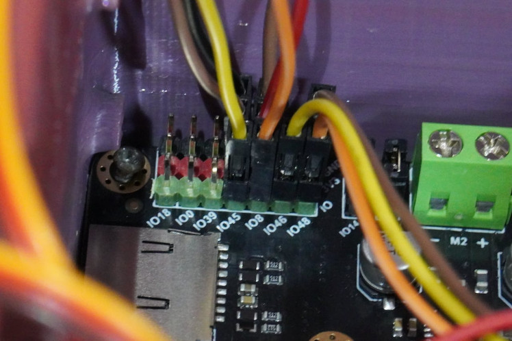
Step 9: Connecting Audio Circuit
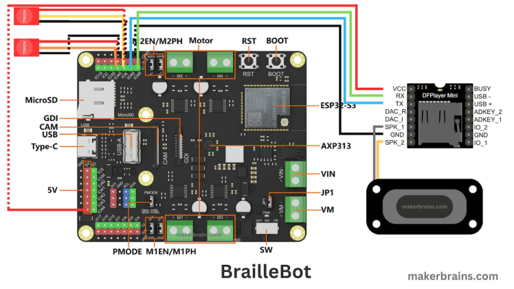
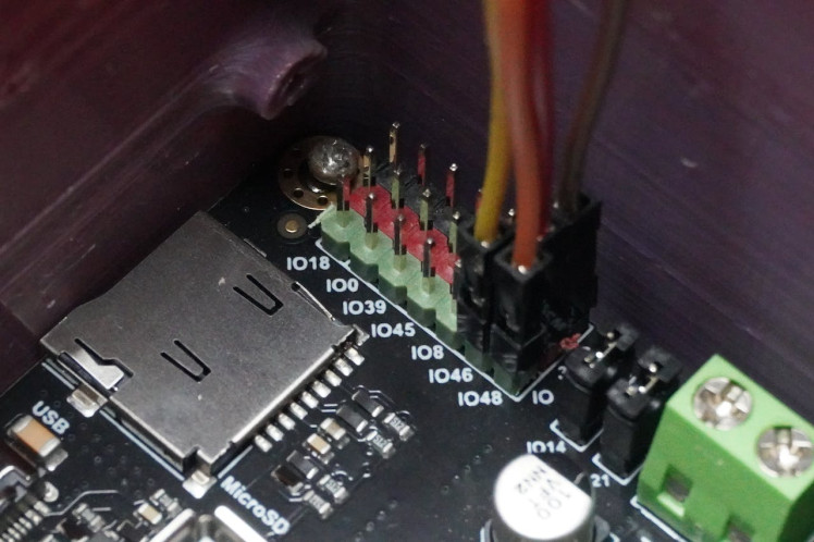
DFPlayer to Romeo ESP32 Connections:
- Connect the GND (Ground) of the DFPlayer to the GND on the Romeo ESP32.
- Connect VCC of the DFPlayer to 5V on the Romeo ESP32.
- Connect RX (Receive) of the DFPlayer to IO48 on the Romeo ESP32.
- Connect TX (Transmit) of the DFPlayer to IO46 on the Romeo ESP32.
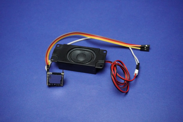
Speaker Connections:
- Connect SPK1 of the DFPlayer to one terminal of the speaker.
- Connect SPK2 of the DFPlayer to the other terminal of the speaker.
Ensure that the connections are secure and accurate, following the circuit diagram.
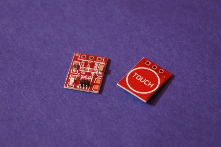
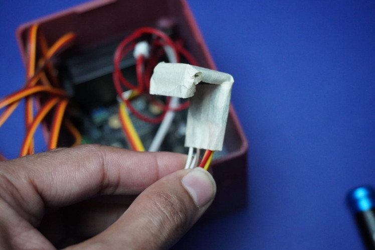
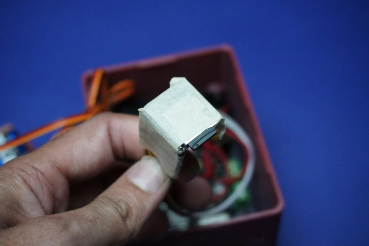
Step 10: Touch Sensor Connection

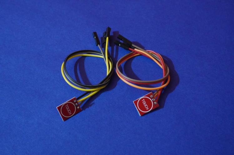
Grab the two touch sensors and connect them by soldering the female jumper wires.
Now, establish the connections:
- Attach Sensor 1 (Next) I/O pin to pin IO45 of the Romeo ESP32.
- Connect Sensor 2 (Previous) I/O pin to pin IO8 Romeo ESP32.
- Also, connection GND to GND and Vcc to 3v3 of both sensors to corresponding Romeo pins, following the guidance provided in the circuit diagram.
Step 11: Final Assembly
To complete the assembly, follow these steps:
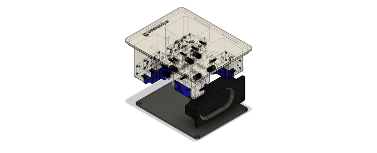
Mounting the Speaker:
- Securely screw the speaker onto the main enclosure. Ensure it is firmly attached.
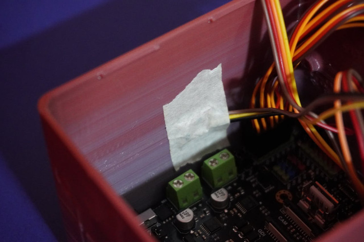
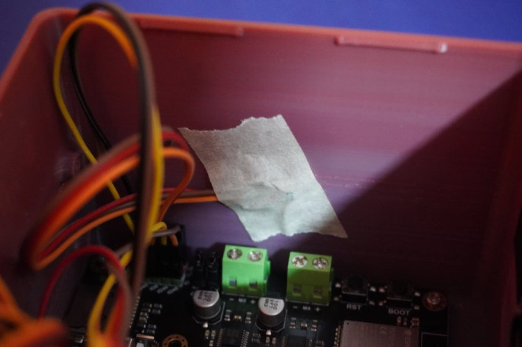
Protecting DFPlayer Connection:
- Use masking tape to cover the open connections of the DFPlayer. This precaution helps protect against potential short circuits.
Placing DFPlayer and Wires:
- Position the DFPlayer and its associated wires inside the main enclosure.
Assembling the Enclosure:
- Align the Top 3D printed part with the main enclosure.
- Snap the Top part onto the main enclosure, ensuring a secure fit.
With these steps completed, your assembly should be finished.
Step 12: Code
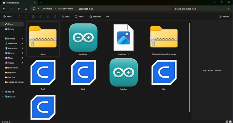
Download the Code from GitHub:
- Visit the GitHub repository: https://github.com/MukeshSankhla/BrailleBot
- Click on the green "Code" button, and then click "Download ZIP."
- Extract the downloaded ZIP file to a location on your computer.
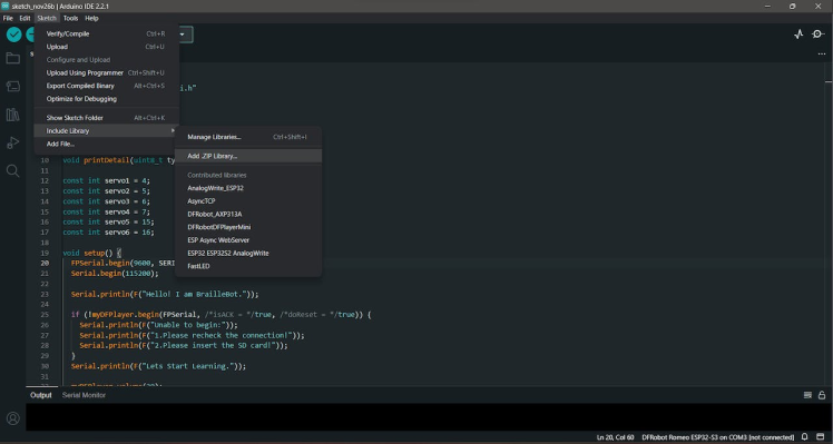
Install DFRobotDFPlayerMini Library:
- Open the Arduino IDE on your computer.
- Click on Sketch in the menu, then select Include Library -> Add.ZIP Library.
- Navigate to the extracted folder and select the "DFRobotDFPlayerMini-master.zip" file. Click "Open" to install the library.
Open and Upload the Code:
- Open the Arduino sketch by navigating to the extracted folder and opening the.ino file.
- In the Arduino IDE, set the board type by clicking on Tools -> Board and selecting the bosrd type as "DFRobot Romeo ESP32-S3".
- Choose the correct port by clicking on Tools -> Port and selecting the port to which your Romeo ESP32-S3 is connected.
- Upload the code to the board by clicking on the right arrow icon (or by selecting Sketch -> Upload).
Code Successfully Uploaded:
- Once the code is successfully uploaded, you should see the message "Done uploading" at the bottom of the Arduino IDE.
Step 13: Code Explanation
setup():
- This function is called once when the Arduino starts.
- It sets up the pin modes for the "Next" and "Previous" buttons, initializes serial communication, and attaches interrupt service routines to these buttons.
- It initializes the DFPlayer module, prints welcome messages to the serial monitor, and performs the initial setup for BrailleBot, including moving the Braille dots and playing the introduction audio.
void setup() {
  pinMode(nextPin, INPUT_PULLUP);
  pinMode(previousPin, INPUT_PULLUP);


  // Set up serial communication
  FPSerial.begin(9600, SERIAL_8N1, /*rx =*/48, /*tx =*/46);
  Serial.begin(115200);


  // Display welcome message
  Serial.println(F("Hello! I am BrailleBot."));


  // Attach interrupts for button presses
  attachInterrupt(digitalPinToInterrupt(nextPin), nextISR, FALLING);
  attachInterrupt(digitalPinToInterrupt(previousPin), previousISR, FALLING);


  // Initialize the DFPlayer module
  if (!myDFPlayer.begin(FPSerial, /*isACK = */true, /*doReset = */true)) {
    Serial.println(F("Unable to begin:"));
    Serial.println(F("1. Please recheck the connection!"));
    Serial.println(F("2. Please insert the SD card!"));
  }


  // Display start message
  Serial.println(F("Let's Start Learning."));


  // Clear Braille display and play introduction audio
  clear();
  delay(1000);
  myDFPlayer.volume(30);
  myDFPlayer.play(27);
  delay(4000);


  // Perform initial setup by moving Braille dots up and down
  for(int i = 0; i < 5; i++){
    up();
    clear();
  }
  play();  // Play the audio for the current Braille letter
}
loop():
- This function runs repeatedly in a loop after the setup() function.
- It checks if the "Next" or "Previous" buttons are pressed using the nextPressed and previousPressed flags.
- If the "Next" button is pressed, it increments the position variable, clears the Braille display, and lifts the corresponding alphabet dots, plays the audio for the new Braille letter. It then resets the nextPressed flag.
- If the "Previous" button is pressed, it decrements the position variable, clears the Braille display, and lifts the corresponding alphabet dots, plays the audio for the new Braille letter. It then resets the previousPressed flag.
void loop() {
  // Check if "Next" button is pressed
  if (nextPressed) {
    position++;
    clear();
    play();  // Play the audio for the new Braille letter
    nextPressed = false;  // Reset the flag
  }


  // Check if "Previous" button is pressed
  if (previousPressed) {
    position--;
    clear();
    play();  // Play the audio for the new Braille letter
    previousPressed = false;  // Reset the flag
  }
}
dot1Up() and dot1Down() to dot6Up() and dot6Down():
- These functions control the movement of each individual Braille dot using a servo motor.
- The dotXUp() functions move the specified dot up by gradually decreasing the servo angle, creating a rising motion.
- The dotXDown() functions move the specified dot down by gradually increasing the servo angle, creating a lowering motion.
- As you can see the dot1, 3 and 5 starts from last position that is 180° and decrements, because these motors are oriented in reverse order.
- Whereas dot2, 4 and 6 starts from 0° and increment.
void dot1Up(){
  for (int pos = 180; pos >= 162; pos--) {
    myservo.write(servo1, pos);
    delay(5);
  }
}
void dot1Down(){
  for (int pos = 162; pos <= 180; pos++) {
    myservo.write(servo1, pos);
    delay(5);
  }
}
.
.
.
.
.
.

void dot6Up(){
  for (int pos = 0; pos <= 10; pos++) {
    myservo.write(servo6, pos);
    delay(5);
  }
}
void dot6Down(){
  for (int pos = 10; pos >= 0; pos--) {
    myservo.write(servo6, pos);
    delay(5);
  }
}
play():
- This function plays the audio associated with the current Braille letter.
- It checks the position variable and calls the corresponding function (e.g., a(), b()) to move the Braille dots and play the audio for that letter.
- If position is 27 (beyond the letter 'z'), it resets position to 1.
void play(){
    if(position == 0){
      position = 1;
    }
    if(position == 1){
      a();
    }
    if(position == 2){
      b();
    }
    .
    .
    .
    .
    .
    .
    if(position == 26){
      z();
    }
    if(position == 27){
      position = 1;
    }
}
clear():
- This function clears the Braille display by moving all dots down.
- It sequentially calls the dotXDown() functions for each Braille dot with a delay between each movement.
void clear(){
  dot1Down();
  delay(100);
  dot2Down();
  delay(100);
  dot3Down();
  delay(100);
  dot4Down();
  delay(100);
  dot5Down();
  delay(100);
  dot6Down();
  delay(100);
}
a() to z():
- These functions each correspond to a Braille letter from 'a' to 'z'.
- Each function calls the appropriate dotXUp() functions to raise the Braille dots into the configuration for that letter and plays the corresponding audio using the DFPlayer module.
void a(){
  dot1Up();
  myDFPlayer.play(2);
  delay(pause);
}


void b(){
  dot1Up();
  dot3Up();
  myDFPlayer.play(3);
  delay(pause);
}
.
.
.
.
.
void z(){
  dot1Up();
  dot4Up();
  dot5Up();
  dot6Up();
  myDFPlayer.play(1);
  delay(pause);
}
up():
- This function raises all Braille dots by calling the dotXUp() functions for each dot.
void up(){
  dot1Up();
  dot2Up();
  dot3Up();
  dot4Up();
  dot5Up();
  dot6Up();
}
nextISR() and previousISR():
- These are interrupt service routines that set the nextPressed and previousPressed flags when the "Next" and "Previous" buttons are pressed, respectively.
void nextISR() {
  nextPressed = true;
}


// Interrupt service routine for "Previous" button
void previousISR() {
  previousPressed = true;
}
Step 14: Calibration

- These servo motors or the arm can have small error because of which the dots may not be lifting to the same height, so we have to calibrate the orientation of each motor.
- As you can see in the dotXUp() and dotXDown() functions the pos values are not same for each motor its because, I have adjusted the values according to my BrailleBot system, so you have to adjust these values according to your tactile sensations.
- Example dotXUp pos values :
for (int pos = 180; pos >= 162; pos--)
for (int pos = 0; pos <= 20; pos++)
for (int pos = 180; pos >= 165; pos--)
for (int pos = 0; pos <= 16; pos++)
for (int pos = 180; pos >= 160; pos--)
for (int pos = 0; pos <= 10; pos++)- Also make sure to adjust the same in dotXDown().
Step 15: Conclusion
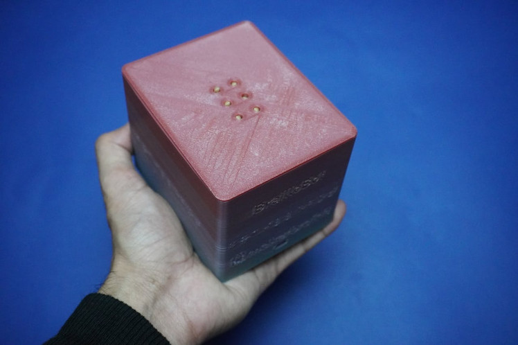
And there you have it — we're all set to explore the Braille alphabets with BrailleBot.
If you encounter any questions or issues during the implementation, feel free to let me know in the comments section. If you've successfully created this project for yourself, remember to share it in the "I Made It" section below.
Throughout this BrailleBot tutorial, I've demonstrated how to create a straightforward Braille alphabet trainer (A to Z). This project offers ample opportunities for customization, so I encourage you to share your improved versions of the project. By doing so, you can contribute to helping others benefit from this tool and facilitate interactive learning for the visually impaired.
Thank you, and I look forward to our next encounter.
Schematics, diagrams and documents
CAD, enclosures and custom parts
Code
Credits
mukesh-sankhla
Tech Educator | Content Creator | Developer | Maker - Simplifying technology through hands-on learning. Creating high-quality tutorials, projects, and insights on electronics, IoT, robotics, CAD, 3D printing, and software development at Empowering students, professionals, and makers with practical, accessible, and inspiring content.
Related products


Leave your feedback...