
Stereo System & Spectrum Analyzer Using The Nordic Audio Dk

Made by knaveen / Communication / Displays / Music
About the project
This project showcases the bi-channel BLE Audio spectrum visualization by making a DIY Stereo using nRF5340 Audio Development Kits
Project info
Difficulty: Moderate
Platforms: Nordic Semiconductor
Estimated time: 2 days
License: GNU General Public License, version 3 or later (GPL3+)
Items used in this project
Hardware components


Software apps and online services
Story
From the very beginning, Bluetooth technology has proven itself to be the go-to solution for wireless audio. These days, Bluetooth audio devices are everywhere from wireless speakers and vehicle infotainment systems to wireless earbuds. With the advent of LE Audio which operates on Bluetooth Low Energy (BLE) introduces a new high-quality, low-power audio codec called the Low Complexity Communications Coded (LC3). LC3 provides high quality even at lower data rates than the standard SBC codec used in Bluetooth Classic implementations. In this project, I am going to make a DIY stereo system that demonstrates audio playback over isochronous channels (ISO) using LC3 codec and the audio data is converted to the frequency domain using the Fast Fourier Transform (FFT). The meaning of the word Isochronous is occurring at the same time but in the context of BLE, it means supporting data transmissions that are a time-sensitive and synchronized rendering of these data streams across multiple receivers.
Hardware Setup
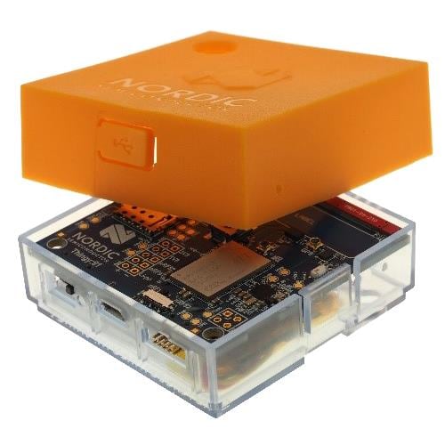
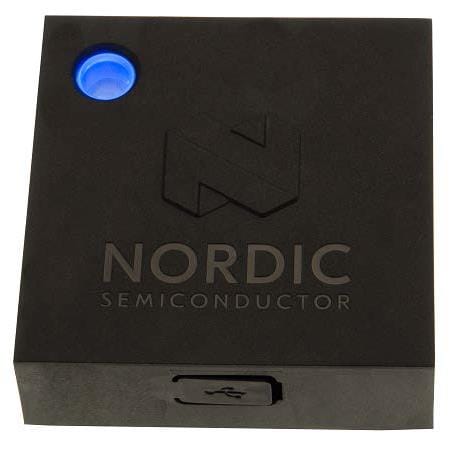
We are using Nordic Semiconductor's nRF5340 Audio Development Kit which is the recommended platform for Bluetooth LE Audio products and can function as a USB dongle to send or receive audio data from a PC. It can also function as a Business Headset, a broadcast receiver, or a True Wireless Stereo (TWS) Earbud. The three main components of this DK are the nRF5340 SoC, nPM1100 PMIC, and Cirrus Logic’s CS47L63 Audio DSP. The CS47L63’s high-performance DAC and differential output driver are optimized for direct connection to an external headphone load.
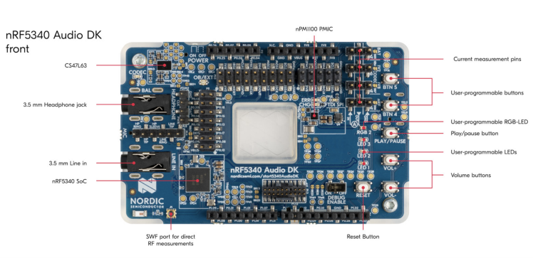
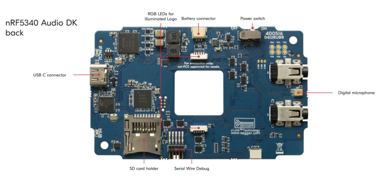
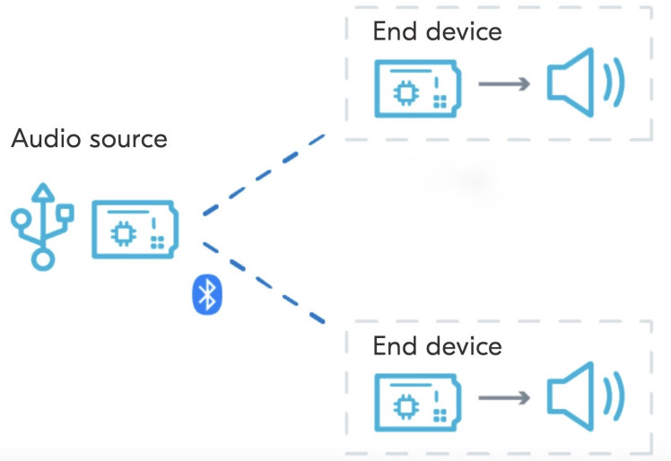
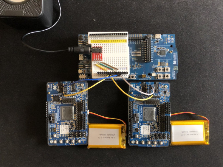
This project requires 3 x Nordic nRF5340 Audio DKs, as 1 x gateway and 2 x headsets devices. The gateway receives the stereo (2-channels) audio data from external sources, computer or smartphone, over USB or I2S (Inter-IC Sound serial bus) and forwards it to the headsets. The headset is a receiver device that plays back the audio it gets from the gateway. Each headset receives mono (1-channel) audio data and can play back on a speaker separately.
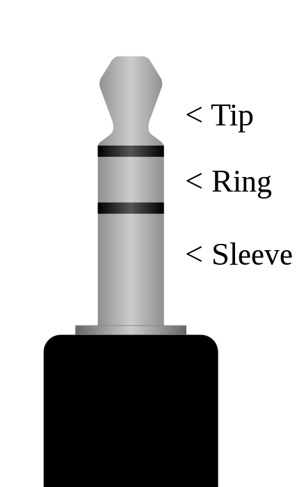
We use a USB stereo speaker with an inbuilt amplifier in this project. This kind of speaker can receive 2-channel (left/right) audio data over a 3.5mm TRS (Tip-Ring-Sleeve) jack. Tip and Ring are usually connected to the left and right mono channels respectively and the sleeve is connected to the ground.
The nRF5340 Audio DK outputs the audio only to the left channel of the HEADPHONE audio jack. This is because of the mono hardware codec chip used on the development kits. We need an external TRS (or TRRS) jack to combine left/right mono channels as shown in the schema below.
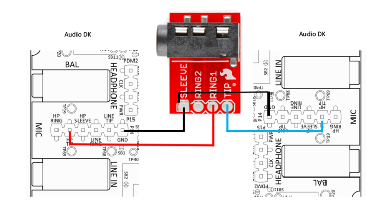
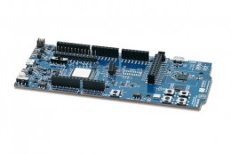
We are using an nRF5340 DK with a breadboard shield to house the TRRS audio jack.
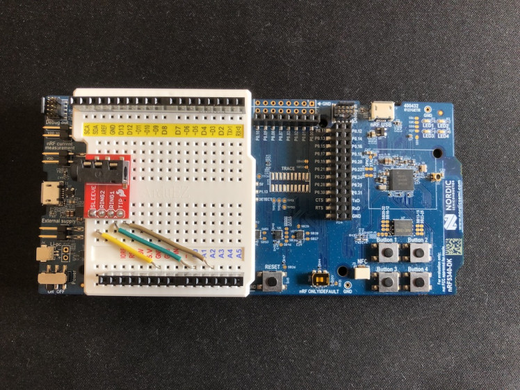
Here the nRF5340 DK serves two purposes, it uses the same connection to bypass DAC output to the TRRS audio jack which is connected to the USB speakers and also it inputs the audio data to the ADC pins, ADC0 and ADC2 for the FFT analysis.

To display the FFT spectrum, a TFT display shield is stacked on top of the breadboard shield.
Setup Development Environment
For the development work, I am using macOS but the setup process is similar for all platforms. First, we need to download nRF connect for Desktop from here:
https://www.nordicsemi.com/Software-and-tools/Development-Tools/nRF-Connect-for-desktop/Download.
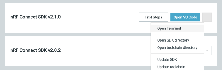
The nRF Connect for Desktop is a cross-platform tool that enables testing and development with nRF5340 Audio DK. Please follow the installation guide in the link above. When the installation is completed, open the app and click on the Toolchain Manager and choose nRF Connect SDK v2.1.0.
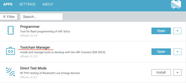
By default, the SDK is installed in the /opt/nordic/ncs directory in MacOS. After installation, click on the Open Terminal which opens up a command line terminal with all environment variables initialized to get started quickly with the development.
Audio DK Application
We will be using the example application located at the /opt/nordic/ncs/v2.1.0/nrf/applications/nrf5340_audio directory. Both device types, gateway, and headsets will use the same code base, but different firmware. The gateway and headsets both run in the connected isochronous stream (CIS) mode which is the default mode of the application. In the default configuration, the gateway application uses the USB serial port as the audio source. Since we will be using a smartphone for the audio data source, we need to switch to using the I2S serial connection by appending the following line to the prj.conf file.
- CONFIG_AUDIO_SOURCE_I2S=y
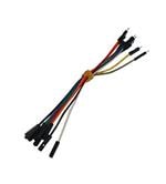
Also, we need an audio jack cable to connect the audio source (smartphone) to the analog LINE IN on the development kit to use I2S. The application workflow for the gateway and headsets is as follows.
Gateway
- The gateway receives audio data from the audio source over I2S.
- Audio data is sent to the synchronization module and then encoded by the software codec.
- The encoded audio data is sent to the Bluetooth LE Host.
- The host sends the encoded audio data to the LE Audio Controller Subsystem for nRF53 on the network core.
- The subsystem forwards the audio data to the hardware radio and sends it to the headset devices.
Headsets
- The headsets receive the encoded audio data on their hardware radio on the network core side.
- The LE Audio Controller Subsystem for nRF53 running on each of the headsets sends the encoded audio data to the Bluetooth LE Host on the headsets’ application core.
- Audio data is sent to the stream control module and placed in a FIFO buffer.
- Audio data is sent from the FIFO buffer to the synchronization module.
- Audio data is decoded by the software codec.
- Decoded audio data is sent to the hardware audio output over I2S.
The nRF5340 Audio application only supports the LC3 software codec, developed specifically for use with LE Audio.
Build and flash the nRF5340 Audio DK firmware
The recommended method for building the application and programming it to the Audio DK is running the buildprog.py Python script, which is located in the /opt/nordic/ncs/v2.1.0/nrf/applications/nrf5340_audio/tools/buildprog directory. The script automates the process of selecting configuration files and building different versions of the application. The script depends on the settings defined in the /opt/nordic/ncs/v2.1.0/nrf/applications/nrf5340_audio/tools/buildprog/nrf5340_audio_dk_devices.json file. We need to find the serial number on the sticker on the nRF5340 Audio DK and update the nrf5340_audio_dk_snr entry in the JSON file as follows.
- [
- {
- "nrf5340_audio_dk_snr": 1050173897,
- "nrf5340_audio_dk_dev": "headset",
- "channel": "left"
- },
- {
- "nrf5340_audio_dk_snr": 1050143142,
- "nrf5340_audio_dk_dev": "gateway",
- "channel": "NA"
- },
- {
- "nrf5340_audio_dk_snr": 1050138112,
- "nrf5340_audio_dk_dev": "headset",
- "channel": "right"
- }
- ]
To build the application for all three Audio DKs, execute the command below at the root directory of the project.
- $ cd /opt/nordic/ncs/v2.1.0/nrf/applications/nrf5340_audio
- $ python3 tools/buildprog/buildprog.py -c app -b debug -d both
The Audio DKs are programmed according to the serial numbers set in the JSON file. Make sure to connect the development kits to your PC using a USB and turn them on using the POWER switch before you run the command below.
- $ python buildprog.py -c both -b debug -d both -p
The nRF5340 DK Application
The nRF5340 DK samples the audio data (DAC output) using ADC pin at 12-bit resolution. In the application, the CPU frequency is set to 128MHz for real-time processing of the incoming ADC samples.
- NRF_CLOCK_S->HFCLKCTRL = (CLOCK_HFCLKCTRL_HCLK_Div1 << CLOCK_HFCLKCTRL_HCLK_Pos);
The complex FFT is calculated using the ARM CMSIS-DSP library which provides optimized compute kernels for the Cortex-M processor cores. A Fast Fourier Transform (FFT) is an algorithm that computes a sequence's discrete Fourier transform (DFT). Fourier analysis converts a signal from its original domain (often time or space) to a representation in the frequency domain. The spectrum, measurement of an FFT analyzer, is displayed on the TFT LCD for each audio channel separately using the LVGL (Light and Versatile Graphics Library). The full code is given below.
- lude <zephyr/zephyr.h>
- #include <lvgl.h>
- #include <hal/nrf_saadc.h>
- #include <arm_math.h>
- #include <arm_const_structs.h>
- #define LOG_LEVEL CONFIG_LOG_DEFAULT_LEVEL
- #include <zephyr/logging/log.h>
- #define ADC_DEVICE_NAME DT_INST(0, nordic_nrf_saadc)
- #define ADC_RESOLUTION 12
- #define ADC_GAIN ADC_GAIN_1_6
- #define ADC_REFERENCE ADC_REF_INTERNAL
- #define ADC_ACQUISITION_TIME ADC_ACQ_TIME(ADC_ACQ_TIME_MICROSECONDS, 10)
- #define ADC_1ST_CHANNEL_ID 0
- #define ADC_1ST_CHANNEL_INPUT NRF_SAADC_INPUT_AIN0 // Arduino Naming A0
- #define ADC_2ND_CHANNEL_ID 2
- #define ADC_2ND_CHANNEL_INPUT NRF_SAADC_INPUT_AIN2 // Arduino Naming A2
- #define ADC_MAX_VAL ((1U << ADC_RESOLUTION) - 1U)
- #define DISP_WIDTH 320
- #define DISP_HEIGHT 240
- #define BUFFER_SIZE 512
- #define WINDOW_SIZE 512
- #define MAG_SCALE 400
- static int16_t m_sample_buffer_1[BUFFER_SIZE];
- static int16_t m_sample_buffer_2[BUFFER_SIZE];
- static float32_t sample_buffer_norm_1[BUFFER_SIZE];
- static float32_t sample_buffer_norm_2[BUFFER_SIZE];
- static float32_t fftInput_1[WINDOW_SIZE*2];
- static float32_t fftOutput_1[WINDOW_SIZE];
- static float32_t fftInput_2[WINDOW_SIZE*2];
- static float32_t fftOutput_2[BUFFER_SIZE];
- LOG_MODULE_REGISTER(app);
- uint32_t colors[] = {
- 0x24c4e6, 0x05a6fb, 0x0571fb, 0x053ffb, 0x0509fb, 0x3305fb, 0x6905fb,
- 0x9705fb, 0xcd05fb, 0xfb05f7, 0xfb05c1, 0xfb058f, 0xfb055a, 0xfb0528,
- 0xfb1505, 0xfb4a05, 0xfb7c05, 0xfbb205, 0xfbe405, 0xe0fb05, 0xaefb05,
- 0x78fb05, 0x46fb05, 0x11fb05, 0x05fb2c, 0x05fb5d, 0x05fb93, 0x05fbc5,
- 0x05fbfb, 0x05c9fb, 0x0593fb, 0x0584fb,
- };
- typedef struct {
- lv_obj_t *obj;
- float values[WINDOW_SIZE];
- float peaks[WINDOW_SIZE];
- int mid_point;
- } spectrum_t;
- spectrum_t spectrum_1;
- spectrum_t spectrum_2;
- const struct device *adc_dev;
- static const struct adc_channel_cfg m_1st_channel_cfg = {
- .gain = ADC_GAIN,
- .reference = ADC_REFERENCE,
- .acquisition_time = ADC_ACQUISITION_TIME,
- .channel_id = ADC_1ST_CHANNEL_ID,
- #if defined(CONFIG_ADC_CONFIGURABLE_INPUTS)
- .input_positive = ADC_1ST_CHANNEL_INPUT,
- #endif
- };
- static const struct adc_channel_cfg m_2nd_channel_cfg = {
- .gain = ADC_GAIN,
- .reference = ADC_REFERENCE,
- .acquisition_time = ADC_ACQUISITION_TIME,
- .channel_id = ADC_2ND_CHANNEL_ID,
- #if defined(CONFIG_ADC_CONFIGURABLE_INPUTS)
- .input_positive = ADC_2ND_CHANNEL_INPUT,
- #endif
- };
- const struct adc_sequence_options sequence_opts = {
- .interval_us = 0,
- .callback = NULL,
- .user_data = NULL,
- .extra_samplings = BUFFER_SIZE -1,
- };
- static int adc_sample(void)
- {
- int ret;
- const struct adc_sequence sequence_1 = {
- .options = &sequence_opts,
- .channels = BIT(ADC_1ST_CHANNEL_ID),
- .buffer = m_sample_buffer_1,
- .buffer_size = sizeof(m_sample_buffer_1),
- .resolution = ADC_RESOLUTION,
- };
- const struct adc_sequence sequence_2 = {
- .options = &sequence_opts,
- .channels = BIT(ADC_2ND_CHANNEL_ID),
- .buffer = m_sample_buffer_2,
- .buffer_size = sizeof(m_sample_buffer_2),
- .resolution = ADC_RESOLUTION,
- };
- if (!adc_dev) {
- return -1;
- }
- ret = adc_read(adc_dev, &sequence_1);
- //LOG_ERR("ADC [0] read err: %dn", ret);
- ret = adc_read(adc_dev, &sequence_2);
- //LOG_ERR("ADC [2] read err: %dn", ret);
- /* print the AIN0, AIN2 values */
- //for (int i = 0; i < BUFFER_SIZE; i++) {
- // LOG_INF("%d, %dn", m_sample_buffer_1[i], m_sample_buffer_2[i]);
- //}
- return ret;
- }
- static void spectrum_draw_event_cb(lv_event_t *e)
- {
- lv_event_code_t code = lv_event_get_code(e);
- if (code == LV_EVENT_REFR_EXT_DRAW_SIZE) {
- lv_event_set_ext_draw_size(e, LV_VER_RES);
- } else if (code == LV_EVENT_COVER_CHECK) {
- lv_event_set_cover_res(e, LV_COVER_RES_NOT_COVER);
- } else if (code == LV_EVENT_DRAW_POST) {
- lv_obj_t *obj = lv_event_get_target(e);
- spectrum_t *spectrum = lv_event_get_user_data(e);
- lv_draw_ctx_t *draw_ctx = lv_event_get_draw_ctx(e);
- lv_opa_t opa = lv_obj_get_style_opa(obj, LV_PART_MAIN);
- if (opa < LV_OPA_MIN) return;
- lv_draw_rect_dsc_t draw_rect_dsc;
- lv_draw_rect_dsc_init(&draw_rect_dsc);
- draw_rect_dsc.bg_opa = LV_OPA_COVER;
- lv_draw_line_dsc_t draw_line_dsc;
- lv_draw_line_dsc_init(&draw_line_dsc);
- draw_line_dsc.width = 1;
- int x_step = (int)(DISP_WIDTH - 16) / (WINDOW_SIZE / 16);
- int bar_count = 1;
- // skip first 2
- for (int i = 2; i < WINDOW_SIZE / 4; i += 4) {
- float ave = 0;
- for (int j = 0; j < 4; j++) {
- ave += spectrum->values[i + j];
- }
- ave /= 4;
- int bar_value = MIN(125.0f, 0.25f * ave);
- ave = 0;
- for (int j = 0; j < 4; j++) {
- ave += spectrum->peaks[i + j];
- }
- ave /= 4;
- int peak_value = MIN(125.0f, 0.25f * ave);
- draw_rect_dsc.bg_color = lv_color_hex(colors[bar_count - 1]);
- /* 5 is the bar width, bar_value is bar height */
- lv_area_t above_rect;
- above_rect.x1 = bar_count * x_step;
- above_rect.x2 = bar_count * x_step + 5;
- above_rect.y1 = spectrum->mid_point - (int)(bar_value / 2);
- above_rect.y2 = spectrum->mid_point;
- lv_draw_rect(draw_ctx, &draw_rect_dsc, &above_rect);
- lv_area_t below_rect;
- below_rect.x1 = bar_count * x_step;
- below_rect.x2 = bar_count * x_step + 5;
- below_rect.y1 = spectrum->mid_point;
- below_rect.y2 = spectrum->mid_point + (int)(bar_value / 2);
- lv_draw_rect(draw_ctx, &draw_rect_dsc, &below_rect);
- draw_line_dsc.color = lv_color_hex(colors[bar_count - 1]);
- lv_point_t above_line[2];
- /* upside line always 2 px above the bar */
- above_line[0].x = bar_count * x_step;
- above_line[0].y = spectrum->mid_point - (int)(peak_value / 2) - 2;
- above_line[1].x = bar_count * x_step + 6;
- above_line[1].y = spectrum->mid_point - (int)(peak_value / 2) - 2;
- lv_draw_line(draw_ctx, &draw_line_dsc, &above_line[0],
- &above_line[1]);
- lv_point_t below_line[2];
- /* under line always 2 px below the bar */
- below_line[0].x = bar_count * x_step;
- below_line[0].y = spectrum->mid_point + (int)(peak_value / 2) + 2;
- below_line[1].x = bar_count * x_step + 6;
- below_line[1].y = spectrum->mid_point + (int)(peak_value / 2) + 2;
- lv_draw_line(draw_ctx, &draw_line_dsc, &below_line[0],
- &below_line[1]);
- bar_count++;
- }
- }
- }
- void create_spectrum_object(spectrum_t *spectrum)
- {
- spectrum->obj = lv_obj_create(lv_scr_act());
- lv_obj_remove_style_all(spectrum->obj);
- lv_obj_refresh_ext_draw_size(spectrum->obj);
- lv_obj_set_size(spectrum->obj, DISP_WIDTH - 16, (DISP_HEIGHT - 16) / 2);
- lv_obj_set_pos(spectrum->obj, 16, spectrum->mid_point - 58);
- lv_obj_clear_flag(spectrum->obj, LV_OBJ_FLAG_CLICKABLE | LV_OBJ_FLAG_SCROLLABLE);
- lv_obj_add_event_cb(spectrum->obj, spectrum_draw_event_cb, LV_EVENT_ALL, spectrum);
- }
- static void update_spectrum(spectrum_t *spectrum, float *magnitudes)
- {
- for (int i = 0; i < WINDOW_SIZE; i++) {
- float mag = magnitudes[i] * MAG_SCALE;
- if (mag > spectrum->values[i]) {
- spectrum->values[i] = mag;
- } else {
- spectrum->values[i] = 0.7 * spectrum->values[i] + 0.3 * mag;
- }
- if (mag > spectrum->peaks[i]) {
- spectrum->peaks[i] = mag;
- } else {
- spectrum->peaks[i] = 0.95 * spectrum->peaks[i] + 0.05 * mag;
- }
- }
- }
- int main(void)
- {
- /* Set CPU frequency to 128 MHz */
- NRF_CLOCK_S->HFCLKCTRL = (CLOCK_HFCLKCTRL_HCLK_Div1 << CLOCK_HFCLKCTRL_HCLK_Pos);
- adc_dev = DEVICE_DT_GET(ADC_DEVICE_NAME);
- if (!adc_dev) {
- LOG_ERR("device_get_binding ADC_0 failedn");
- return -1;
- }
- int err;
- err = adc_channel_setup(adc_dev, &m_1st_channel_cfg);
- err = adc_channel_setup(adc_dev, &m_2nd_channel_cfg);
- if (err) {
- LOG_ERR("Error in adc setup: %dn", err);
- }
- /* Trigger offset calibration
- * As this generates a _DONE and _RESULT event
- * the first result will be incorrect.
- */
- NRF_SAADC->TASKS_CALIBRATEOFFSET = 1;
- while (1) {
- err = adc_sample();
- if (err) {
- LOG_ERR("Error in adc sampling: %dn", err);
- }
- // normalize audio buffer [0.0 - 1.0]
- for (int i = 0; i < BUFFER_SIZE; i++) {
- sample_buffer_norm_1[i] = (m_sample_buffer_1[i] * 1.0f) / ADC_MAX_VAL;
- sample_buffer_norm_2[i] = (m_sample_buffer_2[i] * 1.0f) / ADC_MAX_VAL;
- }
- // calculate mean
- float32_t mean_1, mean_2;
- arm_mean_f32(sample_buffer_norm_1, BUFFER_SIZE, &mean_1);
- arm_mean_f32(sample_buffer_norm_2, BUFFER_SIZE, &mean_2);
- // populate FFT inputs by removing DC bias
- for (int i = 0; i < WINDOW_SIZE*2; i += 2) {
- fftInput_1[i] = sample_buffer_norm_1[i/2] - mean_1; // Re
- fftInput_1[i+1] = 0; // Im
- fftInput_2[i] = sample_buffer_norm_2[i/2] - mean_2; // Re
- fftInput_2[i+1] = 0; // Im
- //printf("%f, %fn", fftInput_1[i], fftInput_2[i]);
- }
- // calculate FFT
- arm_cfft_f32(&arm_cfft_sR_f32_len512, fftInput_1, 0, 1);
- arm_cfft_f32(&arm_cfft_sR_f32_len512, fftInput_2, 0, 1);
- // calculate magnitudes
- arm_cmplx_mag_f32(fftInput_1, fftOutput_1, WINDOW_SIZE);
- arm_cmplx_mag_f32(fftInput_2, fftOutput_2, WINDOW_SIZE);
- k_sleep(K_MSEC(1));
- }
- }
- void display_main(void)
- {
- const struct device *display_dev;
- display_dev = DEVICE_DT_GET(DT_CHOSEN(zephyr_display));
- if (!device_is_ready(display_dev)) {
- LOG_ERR("Device not ready, aborting.");
- while (1) {}
- }
- spectrum_1.mid_point = (DISP_HEIGHT / 4) - 1;
- spectrum_2.mid_point = ((3 * DISP_HEIGHT) / 4) - 1;
- create_spectrum_object(&spectrum_1);
- create_spectrum_object(&spectrum_2);
- display_blanking_off(display_dev);
- while (1) {
- update_spectrum(&spectrum_1, fftOutput_1);
- update_spectrum(&spectrum_2, fftOutput_2);
- lv_obj_invalidate(spectrum_1.obj);
- lv_obj_invalidate(spectrum_2.obj);
- lv_task_handler();
- k_sleep(K_MSEC(1));
- }
- }
- K_THREAD_DEFINE(display_thread, 8192, display_main, NULL, NULL, NULL, 7, 0, 0);
Build and flash the nRF5340 DK application firmware
Execute the command below in the terminal by opening it using the Toolchain manager as described in the Setup Development Environment section.
- $ git clone https://github.com/metanav/nRF5340_Audio_DK_stereo_player_spectrum_analyzer.git
- $ cd nRF5340_Audio_DK_stereo_player_spectrum_analyzer
- $ west build -b nrf5340dk_nrf5340_cpuapp --pristine
Connect the nRF5340 DK using a USB cable and execute the command below.
- $ west flash
Once the flashing is completed successfully, the application starts running. In the working demo, the Audio DKs are powered using the Lipo batteries which come with the bundle. The USB speakers and nRF5340 DK are powered using a power bank and a USB connector. 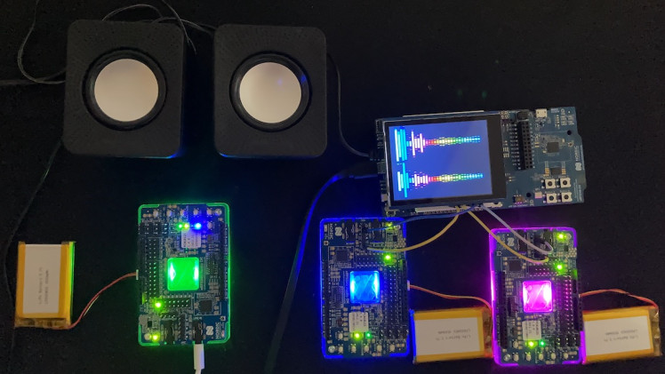
Testing Demo
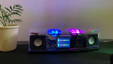
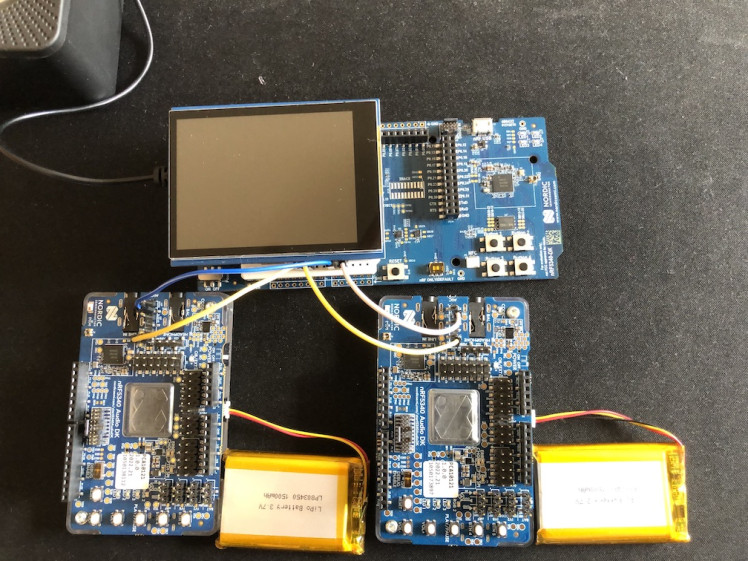
All assemblies are fitted inside a transparent plastic showcase to give it a look and feel of a stereo player. 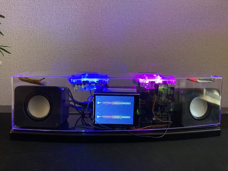
Final Demo
We can see the live demonstration of the audio streaming from a smartphone audio source connected to the Audio DK gateway device to the Audio DK headsets. A real-time FFT spectrum is displayed at the TFT LCD for both channels which can be used as a Spectrum Analyzer and monitor the synchronization of the two mono channels.
Conclusion
The nRF5340 Audio DK is a versatile development kit that contains everything needed to start development. The low-powered and highly synchronized audio streaming capabilities make it a good fit for many audio-based development use cases.
Schematics, diagrams and documents
Code
Credits
Related products


Leave your feedback...