
Bitmap Animation On Ili9341 Tft Touchscreen Display Shield

About the project
Program Arduino with Visuino to animate bitmap on ILI9341 based TFT Touchscreen Display Shield - Quick and Easy!
Project info
Difficulty: Easy
Estimated time: 1 hour
License: GNU General Public License, version 3 or later (GPL3+)
Items used in this project

Software apps and online services
Story
ILI9341 based TFT Touchscreen Display Shields are very popular low cost Display Shields for Arduino. Visuino has had support for them for quite a while, but I never had chance to write a Tutorial on how to use them. Recently however few people asked questions about using displays with Visuino, so I decided to make a tutorial.
In this Tutorial, I will show you how easy it is, to connect the Shield to Arduino, and program it with Visuino to animate a Bitmap to move around on the Display.
Step 1: Components
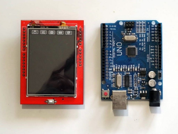
- One Arduino Uno compatible board (It may work with Mega too, but I have not tested the shield with it yet)
1 / 3 • Picture 1

Picture 1

Picture 2

Picture 3
Plug the TFT Shield on top of the Arduino Uno as shown on the pictures.
Step 3: Start Visuino and add TFT Display Shield
1 / 2 • Picture 1

Picture 1

Picture 2
To start programming the Arduino, you will need to have the Arduino IDE installed from here: http://www.arduino.cc/.
Make sure that you install 1.6.7 or higher, otherwise this tutorial will not work!
The Visuino: https://www.visuino.com also needs to be installed.
- Start Visuino as shown in the first picture
- Click on the "Arrow Down" button of the Arduino component to open the Drop Down Menu (Picture 1)
- From the Menu select "Add Shields..." (Picture 1)
- In the "Shields" dialog expand the "Displays" category, and select the "TFT Color Touch Screen Display ILI9341 Shield", then click on the "+" button to add it (Picture 2)
1 / 6 • Picture 1

Picture 1

Picture 2

Picture 3

Picture 4

Picture 5

Picture 6
Next we need to add Graphics elements to render text and bitmap. First we will add graphics element to draw the shadow of the text:
- In the Object Inspector, click on the "..." button next to the value of the "Elements" property of the "TFT Display" Element (Picture 1)
- In the Elements editor select “Draw Text”, and then click on the "+" button (Picture 2) to add one (Picture 3)
- In the Object Inspector set the value of the "Color" property of the "Draw Text1" element to "aclSilver" (Picture 3)
- In the Object Inspector set the value of the "Size" property of the "Draw Text1" element to "4" (Picture 4). This makes the text bigger
- In the Object Inspector set the value of the "Text" property of the "Draw Text1" element to "Visuino" (Picture 5)
- In the Object Inspector set the value of the "X" property of the "Draw Text1" element to "43" (Picture 6)
- In the Object Inspector set the value of the "Y" property of the "Draw Text1" element to "278" (Picture 6)
1 / 4 • Picture 1

Picture 1

Picture 2

Picture 3

Picture 4
Now we will add graphics element to draw the text:
- In the Elements editor select “Draw Text”, and then click on the "" button (Picture 1) to add second one (Picture 2)
- In the Object Inspector set the value of the "Size" property of the "Draw Text1" element to "4" (Picture 2)
- In the Object Inspector set the value of the "Text" property of the "Draw Text1" element to "Visuino" (Picture 3)
- In the Object Inspector set the value of the "X" property of the "Draw Text1" element to "40" (Picture 4)
- In the Object Inspector set the value of the "Y" property of the "Draw Text1" element to "275" (Picture 4)
1 / 5 • Picture 1

Picture 1

Picture 2

Picture 3

Picture 4

Picture 5
Next we will add graphics element to draw the bitmap:
- In the Elements editor select “Draw Bitmap”, and then click on the "" button (Picture 1) to add one (Picture 2)
- In the Object Inspector, click on the "..." button next to the value of the "Bitmap" property of the "Draw Bitmap1" Element (Picture 2) to open the "Bitmap Editor" (Picture 3)
- In the "Bitmap Editor" click on the "Load..." button (Picture 3) to open the File Open Dialog (Picture 4)
- In the File Open Dialog, select the bitmap to draw, and click on the "Open" button (Picture 4). If the file is too big it may not be able to fit in the Arduino memory. If you get out of memory error during the compilation, you may need to select a smaller bitmap
- In the "Bitmap Editor" click on the "OK." button (Picture 5) to close the dialog
1 / 4 • Picture 1

Picture 1

Picture 2

Picture 3

Picture 4
To animate the Bitmap, we need to control its X and Y position. For this we will add pins for the X and Y properties:
- In the Object Inspector click on the "Pin" button at front of the "X" property of the "Draw Bitmap1" element (Picture 1), and select "Integer SinkPin" (Picture 2)
- In the Object Inspector click on the "Pin" button at front of the "Y" property of the "Draw Bitmap1" element (Picture 3), and select "Integer SinkPin" (Picture 4)
1 / 4 • Picture 1

Picture 1

Picture 2

Picture 3

Picture 4
We will use 2 Integer sine generators to animate the bitmap movement:
- Type "sine" in the Filter box of the Component Toolbox then select the "Sine Integer Generator" component (Picture 1), and drop two of them it in the design area
- In the Object Inspector, set the value of the "Amplitude" property of the SineIntegerGenerator1 component to "96" (Picture 2)
- In the Object Inspector, set the value of the "Offset" property of the SineIntegerGenerator1 component to "96" (Picture 3)
- In the Object Inspector, set the value of the "Frequency" property of the SineIntegerGenerator1 component to "0.2" (Picture 4)
1 / 5 • Picture 1

Picture 1

Picture 2

Picture 3

Picture 4

Picture 5
- In the Object Inspector, set the value of the "Amplitude" property of the SineIntegerGenerator2 component to "120" (Picture 1)
- In the Object Inspector, set the value of the "Offset" property of the SineIntegerGenerator2 component to "120" (Picture 2)
- In the Object Inspector, set the value of the "Frequency" property of the SineIntegerGenerator2 component to "0.03" (Picture 3)
- Connect the "Out" output pin of the SineIntegerGenerator1 component to the "X" input pin of the "Shields.TFT Sisplay.Elements.Draw Bitmap1" element of the Arduino component (Picture 4)
- Connect the "Out" output pin of the SineIntegerGenerator2 component to the "Y" input pin of the "Shields.TFT Display.Elements.Draw Bitmap1" element of the Arduino component (Picture 5)
1 / 6 • Picture 1

Picture 1

Picture 2

Picture 3

Picture 4

Picture 5

Picture 6
To render the bitmap every time the X and Y position are updated we need to send a clock signal to the "Draw Bitmap1" element. To send the command after the positions have been changed, we need a way to synchronize the events. For this we will use Repeat component to constantly generate events, and Clock Multi Source to generate 2 events in sequence. The first event will clock the sine generators to update the X and Y positions, and the second will clock the "Draw Bitmap1" :
- Type "repeat" in the Filter box of the Component Toolbox, then select the "Repeat" component (Picture 1), and drop it in the design area (Picture 2)
- Type "multi" in the Filter box of the Component Toolbox, then select the "Clock Multi Source" component (Picture 2), and drop it in the design area (Picture 3)
- Connect the "Out" output pin of the Repeat1 component to the "In" input pin of the ClockMultiSource1 component (Picture 3)
- Connect the "Pin[ 0 ]" output pin of the "Out" pins of the ClockMultiSource1component to the "In" input pin of the SineIntegerGenerator1 component (Picture 4)
- Connect the "Pin[ 0 ]" output pin of the "Out" pins of the ClockMultiSource2component to the "In" input pin of the SineIntegerGenerator1 component (Picture 5)
- Connect the "Pin[ 1 ]" output pin of the "Clock" input pin of the "Shields.TFT Display.Elements.Draw Bitmap1" element of the Arduino component (Picture 6)
1 / 2 • Picture 1

Picture 1

Picture 2
- In Visuino, Press F9 or click on the button shown on Picture 1 to generate the Arduino code, and open the Arduino IDE
- In the Arduino IDE, click on the Upload button, to compile and upload the code (Picture 2)
1 / 5 • Picture 1

Picture 1

Picture 2

Picture 3

Picture 4

Picture 5
Congratulations! You have completed the project.
Pictures 2, 3, 4 and 5 and the Video show the connected and powered up project. You will see the Bitmap moving around the ILI9341 based TFT Touchscreen Display Shield as seen on the Video.
On Picture 1 you can see the complete Visuino diagram.Also attached is the Visuino project, that I created for this tutorial, and the bitmap with the Visuino logo. You can download and open it in Visuino: https://www.visuino.com
Credits
Related products


Leave your feedback...