

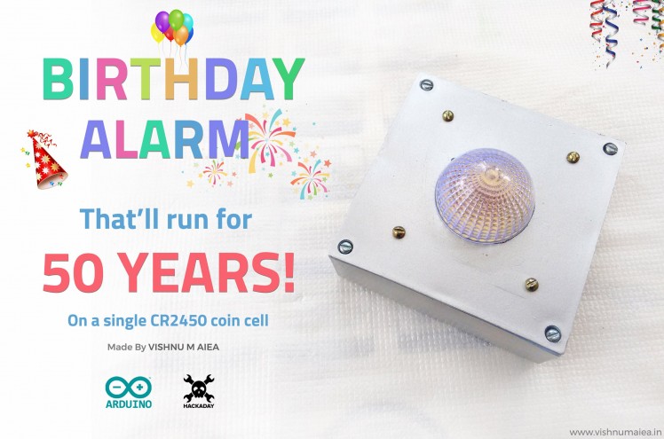
Birthday Alarm That'll Run For 50 Years

Made by vishnumaiea / Clocks / Kids & Family / Lights
About the project
An Arduino powered birthday reminder device that'll wish you happy birthday for 50 years on a single CR2450 coin cell.
Project info
Items used in this project
Hardware components


View all
Hand tools and fabrication machines

Story
Yes, you read the title correct. Have you ever forgot your birthday, that you need someone else to remind you about it ? Or what if you can gift to someone you love, a device that'll wish them on their birthday for 50 times ? I kid you not, this simple Arduino powered Birthday Alarm that runs on a single CR2450 coin cell can wish your loved ones (or yourself) a happy birthday for 50 years, before the battery run out of juice.
I think this is the first time somebody makes a birthday alarm like this, because I tried searching for similar projects but found nothing.
I built this as part of the Hackaday Coin Cell Challenge. This birthday alarm thing simply popped into my mind and I started researching how long we can run something on a coin cell. I've never used the sleep modes of any microcontrollers before. So I had to learn everything about making MCUs run at insanely low currents and save every bit of energy from a cell. It was a challenge really! I used ATmega168P as the microcontroller (actually I modified an Arduino Nano that has ATmega168P on it by removing all the unwanted components such as the voltage regulator, USB bridge etc.) and used Arduino IDE to develop the firmware.
The time and birthday date can be programmed via serial monitor over USB. Once the time and alarm are set, the MCU goes to sleep mode. When the current RTC time matches your birthday every year, the LED will flash for a minute and will print a happy birthday message to the serial monitor. The average current consumption is around 1.2 uAh (including self-discharge) which makes it possible to run it for more than 50 years on a CR2450 (540mAh) Lithium coin cell.
Features
- Around 1.22 uAh average current consumption including cell self-discharge (608 nA without considering self-discharge, as measured by ammeter, on cell CR2450N)
- Actual operating times on different types of Lithium coin cells are : >29 years on CR2023 (225 mAh), >50 years on CR2450N (540 mAh), and >64 years on CR2477N (950 mAh). [actual operating time depends on the battery's physical and chemical health over the period]
- Birthday can be set and updated via any serial monitor software over USB with simple commands.
- Dedicated time setting switch allows to set, see and update time anytime you want.
- Software setting of time means, it can be set pretty accurately with an app running on a computer (a time setting/syncing software based on Processing is under development)
- Open source - all design files and software codes are available to download with detailed documentation and high resolution images.
Now I'll walk you through the instructions on how to build this and show you the actual current consumption test.
Step 1: Modifying the Arduino Nano
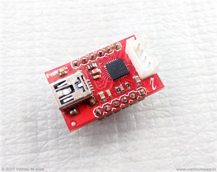
For this project you can use a bare microcontroller or use an Arduino Nano or Mini boards. All that is required is we must run it with internal oscillator (1MHz) and at full 1.8 - 5V operating range. The CR2450 or similar Lithium cells have a nominal voltage of 3V, and so we can run the MCU without using a voltage regulator. Chinese clones or Nano and Mini are extremely cheap that you can buy them for the chip's price! I used such a Nano clone that has CH340G as the USB to serial bridge. Below is the one I used.
 This has ATmega168P-AU
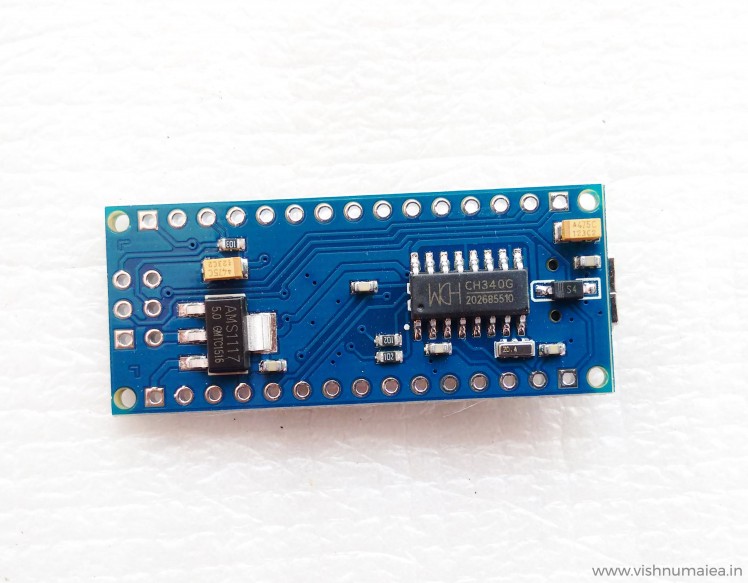 There might be variations in the PCBs
I had both ATmega168 and 328 versions. I bought the 168 versions by mistake a few years ago (now I found a use for it). In this particular board you need to remove,
- The USB to Serial bridge IC which here is the CH340G.
- The Shchottky diode that is connected to the USB 5V.
- Two 1K resistors connected to the TX and RX pins of the CH340G.
- RX, TX and PWR LEDs (SMD)
- The AMS1117 5V voltage regulator.
I used the LED on pin 13 for debugging and as the main flasher, and so I didn't remove it. The capacitors need not be removed as they'll help attenuate noise. Once the regulator is removed, you need to short the pads of the voltage regulator as shown in the image. This is due to the routing used in the PCB design. Do not remove the crystal oscillator of the MCU yet because we'll need it to change the fuse bits. The MCUs will be having the default Arduino boot-loader and fuse settings that makes it run at external 16MHz crystal. If we remove the crystal before setting the fuse to use internal OSC, we simply can't program the chip with an ISP programmer. Below is the modified version of the Arduino Nano.
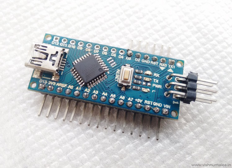 I still haven't removed the TX and RX LEDs here yet but you need to.
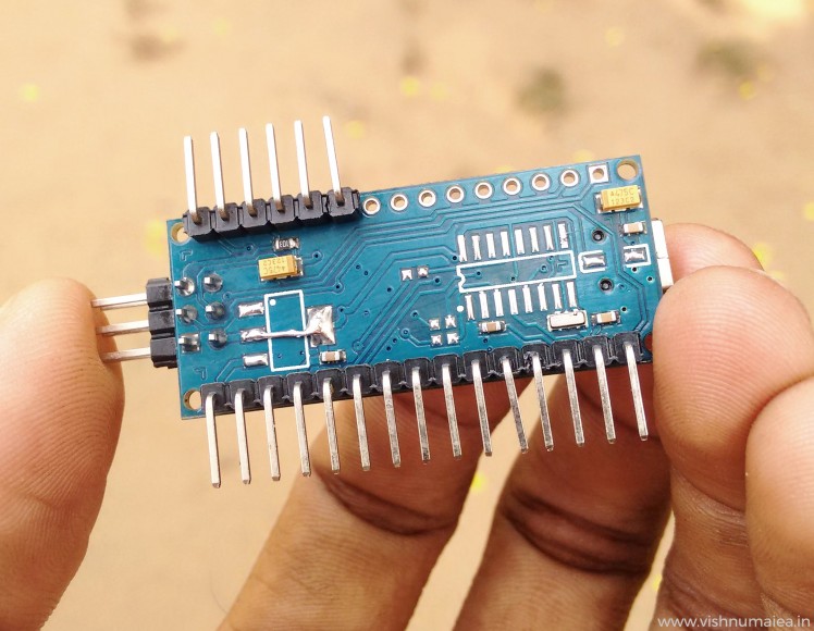 Look how I've shorted the pads of the voltage regulator
Step 2: Changing Fuse Bits of ATmega168P
Normally, the chips on the Arduino boards will be coming with the Arduino bootloader and fuse bits. We need to change this in order to run the MCU at lower power mode. In order to achieve this we need to,
- Make the MCU run at 1MHz. We can enable the internal oscillator and also the "divide by 8" bit to produce 1MHz clock from the 8MHz. Less clock speed, lesser will be the power consumption. We won't be crunching any numbers here, so 1MHz is more than enough.
- Disable the brown-out detection (BOD) module.
- Disable all the internal modules such as ADC, Timers etc. We'll do this in software.
- Disable watchdog timer (WDT).
- Make all the IO pins inputs and LOW except pins 13, 2 and 3.
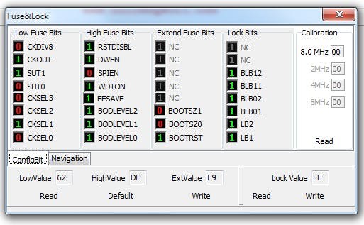 Fuse configuration for ATmeag168P
Above is the fuse settings for ATmega168P. Note that you need the "P" versions of the ATmega chips because they have the pico-power feature. The normal versions (non P) don't support these extra power saving modes. So make sure you get the P versions. You might now wonder why I'm using 168 instead of 328. That's because when I was testing the circuit, 328 seemed consuming around 30uA for the same code and setting I used for 168 which only consumed around 2uA. I don't know why this is. Like I said before, this is the first time I'm fiddling around with power saving modes such as deep sleep. So I might be missing something. If you know anything about it, please let me know in the comments.
To change the fuse bits, we need an ISP programmer. There are many ISP programmers and compatible softwares. I used the USBasp as programmer and ProgISP as programming software. The chip ID or signature of the ATega168P-AU I used is 1E940B. This might change depending on the version you have. To change the fuse bits:
- Connect the USBasp to Nano. Normally, USBasp will have a 10-pin connector but Nano has 6-pin ISP header. So I made a simple 10-pin to 6-pin adapter. You might need to make something similar or find a cable.
- Select the MCU model from the list and verify the signature with the RD button.
- Set the checkboxes and fuse bits as shown in the image below and use the Auto button or the Write button on the fuse setting window to update the fuse bits.
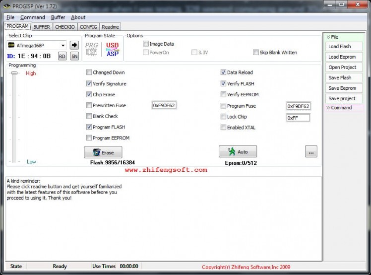 ProgISP window
If successful, a message will be printed to the console. From now on you'll need the ISP to flash the MCU. Below is the USBasp I used.
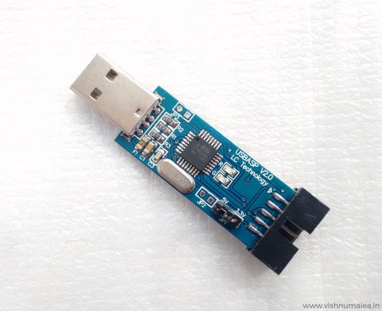 With 10-pin connector

Step 3: Compiling and Uploading
Now that we have changed the fuse bits of our microcontroller, we also need to tell the Arduino software and the compiler about the changes we made so that we can compile the code properly inside the Arduino IDE. How we do this is by adding a custom board definition in the "boards.txt" file that resides in the Arduino installation directory that is normally at <installed location>/Arduino/hardware/arduino/avr/boards.txt" on Windows systems. This might might be different for you depending on which OS you have, or version of the IDE you have. I'm using the IDE version 1.8.5
Once we locate the boards.txt file, you need to add a custom definition of a new Arduino Pro Mini board. Around line 655 will be the starting of the existing Pro Mini board definitions. There'll be many versions of the boards. So we need to add a new variant. Add the following definition to it and save.
## Arduino Pro or Pro Mini (3.3V, 1 MHz) w/ ATmega168
## --------------------------------------------------
pro.menu.cpu.1MHzatmega168=ATmega168 (3.3V, 1 MHz)
pro.menu.cpu.1MHzatmega168.upload.maximum_size=14336
pro.menu.cpu.1MHzatmega168.upload.maximum_data_size=1024
pro.menu.cpu.1MHzatmega168.upload.speed=19200
pro.menu.cpu.1MHzatmega168.bootloader.low_fuses=0x62
pro.menu.cpu.1MHzatmega168.bootloader.high_fuses=0xDF
pro.menu.cpu.1MHzatmega168.bootloader.extended_fuses=0xF9
pro.menu.cpu.1MHzatmega168.bootloader.file=atmega/ATmegaBOOT_168_pro_8MHz.hex
pro.menu.cpu.1MHzatmega168.build.mcu=atmega168
pro.menu.cpu.1MHzatmega168.build.f_cpu=1000000L
And here's a screenshot.
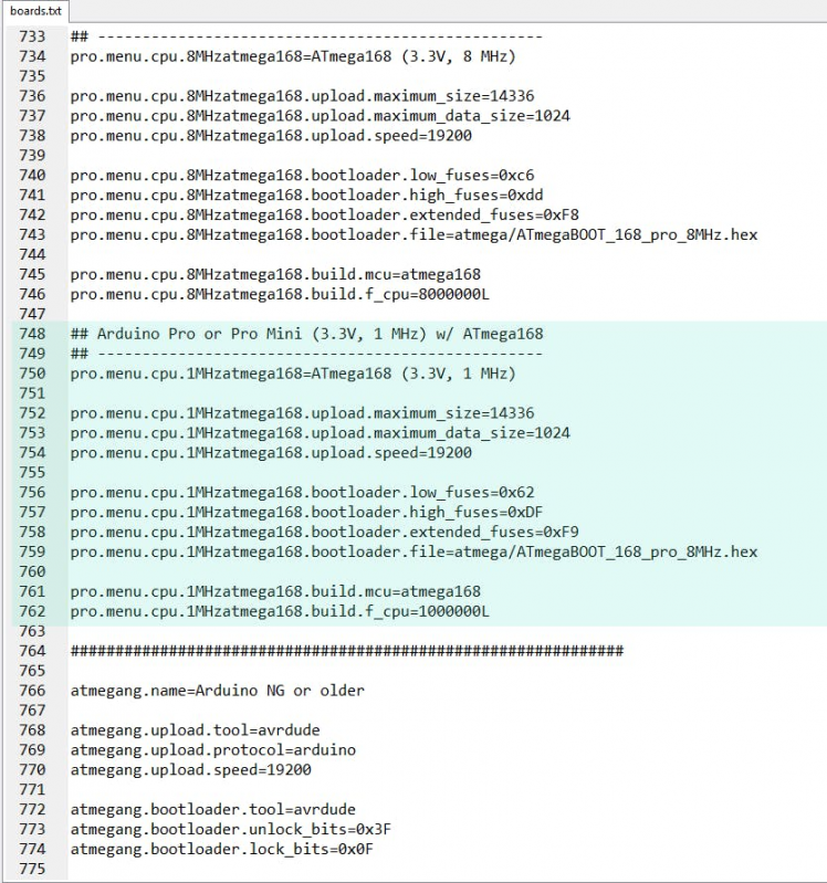 The highlighted part is the new board definition/variant
You need to edit the boards.txt while the Arduino is not running. Once you save the new boards.txt file and restart Arduino IDE you'll see the new board we just added in the list. Take a look at the screenshots below.
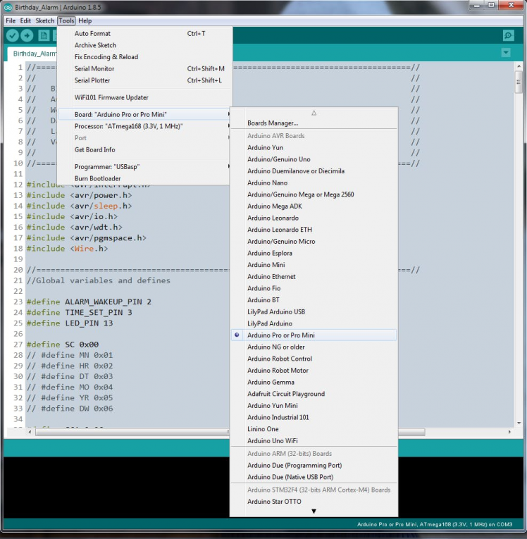 Select Arduino Pro or Pro Mini
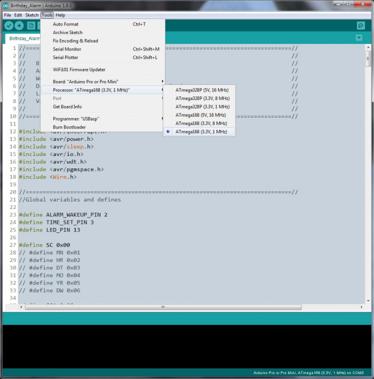 And then 3.3V, 1MHz version we just added
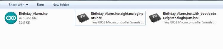
Now we're ready to compile Arduino codes for our new board. As we're not using the Arduino bootloader (BL), we need to create a hex file of the program and use USBasp and ProgISP to flash the microcontroller. We can do this using the "Export compiled binary" option from Sketch menu of the IDE or hit Ctrl + Alt + S. When we do that, two hex files (intel format) will be created in the same directory our sketch resides. One hex file is with BL, and the other is without BL.
Once we have the hex file, in the ProgISP choose the Load Flash option to load the hex file we want to flash the MCU with then hit Auto button. If uploading is success, it'll be printed to the ProgISP's console.
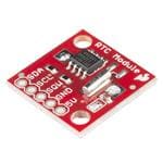
Step 4: Intersil ISL1208 I2C RTC
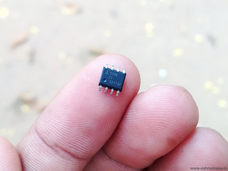
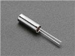
The Intersil ISL1208 is a low power RTC chip with I2C interface. It uses an external 32.768 KHz crystal to keep track of the time. Has month-date-hour-min-sec alarm registers. It only consumes around 400 nA at VBAT operation and a maximum of 1.2 uA at VDD. The operating voltage is from 1.8V to 5.5V. What makes this a good candidate are the power consumption and the month-date alarm feature. Normal RTCs such as DS1307 doesn't have a month setting in alarm register without which we can't generate a birthday alarm every year. It has an interrupt output pin which will generate a 250 mS active LOW signal when the current time matches the alarm date and time. We'll use this to wake the MCU up from sleep mode which I'll explain further below.
Features of ISL1208
- Real Time Clock/Calendar
- -Tracks Time in Hours, Minutes, and Seconds
- - Day of the Week, Day, Month, and Year
- 15 Selectable Frequency Outputs
- Single Alarm
- - Settable to the Second, Minute, Hour, Day of the Week, Day, or Month
- - Single Event or Pulse Interrupt Mode
- Automatic Backup to Battery or Super Capacitor
- Power Failure Detection
- On-Chip Oscillator Compensation
- 2 Bytes Battery-Backed User SRAM
- I2C Interface
- - 400kHz Data Transfer Rate
- 400nA Battery Supply Current
- Same Pin Out as ST M41Txx and Maxim DS13xx Devices
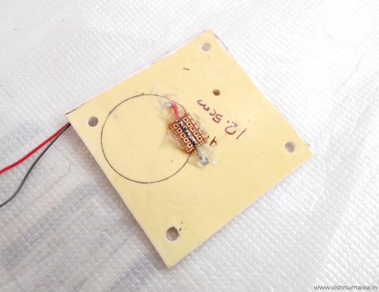
As I had an SMD version of the ISL1208 I had to make a breakout board in order to be plugged onto my main board. Below is what I made.
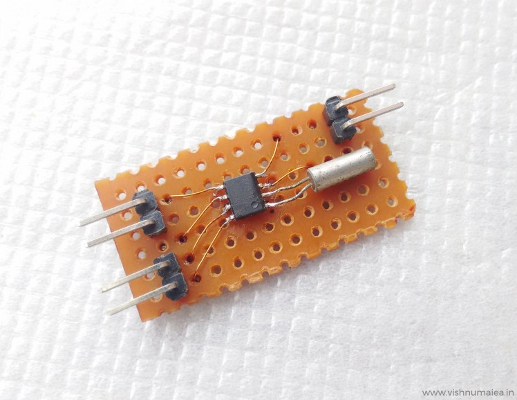 My little breakout board. I'll modify the berg connectors later.
 Make sure to clean the PCB after soldering.
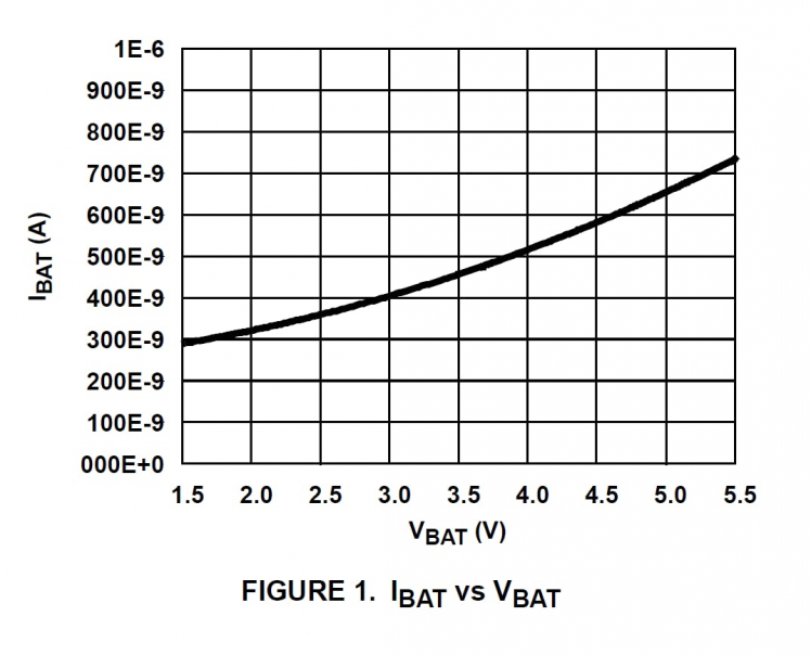 Time keeping current while on VBAT
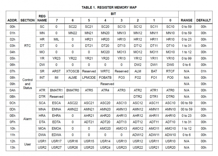 Register map of ISL1208
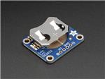
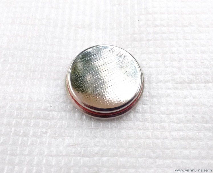
Step 5: CR2450N Coin Cell
; ; 1 / 2
1 / 2
Specifications
- Chemical System - Li / MnO2 (According to IEC 60086)
- Nominal Voltage - 3 V
- Rated Capacity - 540 mAh
- Standard Discharge Current - 0.8 mA
- Max. Cont. Discharge Current - 3.0 mA
- Average Weight - 5.9 g
- Operating Temperature* - -40 - +85 °C
- Self Discharge at 23°C - < 1% / year
- Shelf life - up to 10 years
Step 6 : Schematic
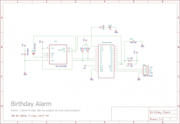
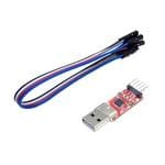
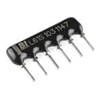
Use the above schematic to solder the modules on a perfboard. The two 4.7K resistors are the I2C pull-ups. The values can range from 3.3K to above 5.6K. The R2 and R3 are pull-ups for the interrupt pins. Arduino Nano has two hardware interrupt pins - digital pin 3 and 2. Digital pin 2 will be used for the alarm wake up interrupt from the RTC and digital pin 3 will be used to wake the MCU up when you need to set the time. Below is the CP2102 USB-to-Serial module I used.
 CP21012 USB-to-Serial Breakout from rhydoLabz
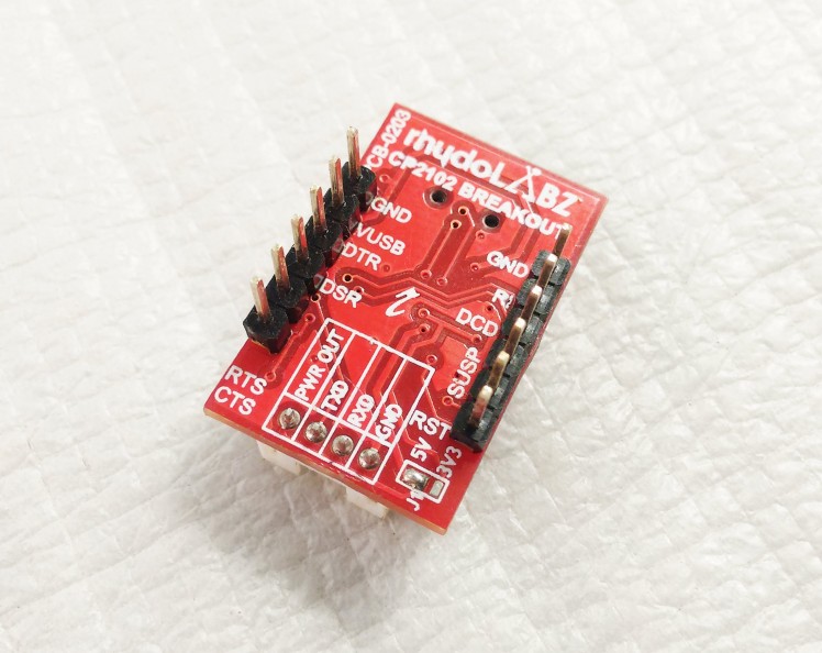 CP21012 USB-to-Serial Breakout from rhydoLabz
The USB-to-Serial module will be used to communicate over the serial monitor. The RX and TX pins of CP2102 are connected to RX and TX pins of Nano respectively. Note that you shouldn't connect the +5V from the USB to the main VCC voltage.
Step 7: How Does It Work?
The working of the device actually quiet simple. Let's see how the main algorithm works,
- Set the current time on the RTC via serial monitor.
- Set the alarm time and date on the RTC.
- The MCU goes to sleep mode after setting the time and alarm by disabling the internal peripherals including timers and ADC.
- When the current time matches the alarm date and time (MM, DD, hh, mm, ss, p) the RTC will generate and interrupt and wake the MCU up from sleep.
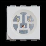
- Up on waking up, the MCU will enable the required internal peripherals and print a happy birthday message to the serial monitor. It also flashes the LED inside the dome in a certain pattern.
- After wishing you a happy birthday, the MCU will go to sleep mode again and will only wake up on your birthday next year.
- But you can see the time and update it whenever needed by turning the time update switch ON.
When powered up for the first time, all RTC registers will be zero and it doesn't increment until we first write to any of them. To set the time on the RTC,
- Turn the time update switch ON (connect the digital pin 3 to GND). We can not set time without pulling the pin 3 LOW.
- First connect the device to your computer with a USB cable. A COM port will be established on your PC to communicate.
- Find the COM port of the device from device manager.
- Open any serial monitor software or Arduino serial monitor with the COM port of the device.
The MCU will print the below message to the serial monitor.
Serial Established.
Ready to update time.
- Sending "t" command will print the current time, "a" will print the alarm date and time, and "c" will cancel the time setting operation and put the MCU into sleep mode after 6 seconds.
- You need to send the current time in the format shown below,
TYYMMDDhhmmssp#
Where:
- T = indicates time information
- YY = least significant digits of a year (eg. 18 for 2018, range is from 00 to 99)
- MM = month (eg. 01 for January, range is 01 to 12)
- DD = date (eg. 24, range is 01 to 31)
- hh = hours (eg. 06, range is 01 to 12 for 12 hour format)
- mm = minutes (eg. 55, range is 00 to 59)
- ss = seconds (eg. 30, range is 00 to 59)
- p = period of the day for 12 hour format (0 = AM, 1 = PM)
- # = delimiter
For example, to set the time and date "08:35:12 AM, 05-01-2018", we should send:
T1801050835120#
To the device where:
- T = indicates time information
- 18 = the year 2018
- 01 = month January
- 05 = date
- 08 = hours
- 35 = minutes
- 12 = seconds
- 0 = AM
- # = delimiter
If the operation is successful the MCU will print the received time to the console as:
Time update received = T1801050835120
Date and Time is 8:35:12 AM, 5-1-18
If the time string you entered is invalid, the below message will be printed:
Invalid time input - <original string>, <length of original string>
Once you successfully set the time, the RTC will keep track of it as long as there's power available to it. You can verify the time you just set by sending the "t" command. Setting the alarm is similar to this except the data format is different. To set the alarm you need to send it as:
AMMDDhhmmssp#
Where:
- A = indicates alarm information
- MM = month
- DD = date
- hh = hours
- mm = minutes
- ss = seconds
- p = time period (0 = AM, 1 = PM)
- # = delimiter
Note that there's no year information with the alarm string because obviously we don't need it. For example to set my birthday "08:00:00 AM, 28-08" I need to send:
A08240800000#
You can check the alarm time anytime with the command "a". Once the alarm time and date is set it's time to put the MCU into sleep. So the device will print the following message:
Everything's set. Please disable the time set pin now.
Now you need to turn the time setting switch OFF ie, pull the digital pin 3 HIGH (the 10K pull-up will do that). The system won't sleep until you do this. When the time setting switch is turned OFF, the device will enter into sleep mode in 6 seconds and print the below message before it.
Well done! Sleeping in 6 seconds..
So that's how you set the time and alarm. Now whenever you need to check the time or update it, you can turn on the timer setting switch and the system will wake up, establish serial communication and prompt you to send the time. It will print the following message up on waking up,
Serial Established.
Time update wake up.
Ready to update time.
If you're just checking if time is correct and don't want to change anything, send "c" command to cancel the operation and put the system into sleep again. You need to also disable the time setting switch at this point.
When the current time matches the alarm time ie. your birthday, the RTC will generate a 250mS interrupt signal to the digital pin 2 of the Nano. This signal will wake up the system. Up on waking up, the device will know that it's your birthday and will establish serial communication (only if you have the USB connected) and print the following message,
Tada! It's your birthday! Happy B'Day <your name> :)
See you on your next birthday! TC. Bye!
Sleeping in 6 seconds..
And it'll also flash the LED connected to digital pin 13. Here's a screenshot of the Arduino serial monitor while I was testing the system.
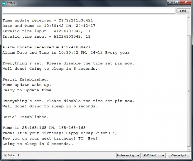 The discrepancy in the messages is because this was taken while testing and it still had bugs!
So that's how you operate this device. To understand this in the code level read the next section.
Step 8: Code
This project is completely open source and therefore I've published the source code for the firmware on my GitHub at https://github.com/vishnumaiea/Birthday-Alarm/ under MIT License. You're free to adapt, modify and redistribute without any restrictions. If you would add a backlink to this project from your modified one, that'd be appreciated. I've thoroughly commented the code and made it straight forward wherever possible.
We have total 13 functions/procedures in the code. They are:
1. void setup()
This is the Arduino's setup function that'll initialize everything and set the configuration registers of the ISl1208 RTC.
2. void loop()
The main loop function.
3. void sleepNow()
This function terminates all communications, disables the MCU's internal peripherals, attaches the interrupts to digital pins 3 and 2, and puts the system into deep sleep mode. Up on any interrupt, the program execution continues from the line after sleep_mode() . Note that before this normal program execution resumes, the MCU would've completed the interrupt service routines associated with the interrupt pins which are alarmInterrupt() and timeUpdateInterrupt()
4. void alarmInterrupt()
The ISR associated with the INT0 interrupt on digital pin 2.
5. void timeUpdateInterrupt()
The ISR associated with the INT1 interrupt on digital pin 3.
6. void fetchTime()
fetchTime() reads the time registers of the RTC and will print the current time to the console.
7. void blinkLED()
Blinks the LEDs obviously.
8. bool establishSerial()
Establishes serial communication with the help of USB-to-Serial module.
9. bool endSerial()
Ends serial communication.
10. byte bcdToDec(byte)
Accepts a BCD (Binary Coded Digits) value and translate it into corresponding decimal value. We need this because the RTC registers only stores and accepts BCD values. So we need to convert to and from BCD occasionally.
11. byte decToBcd(byte)
Accepts a decimal value and translates it into corresponding BCD value.
12. void printTime()
Reads the RTC time registers and prints the current time to the console when "t" command is received.
13. void printAlarmTime()
Reads the RTC alarm registers and prints the alarm time and date to the console when the "a" command is received.
Step 9: Testing
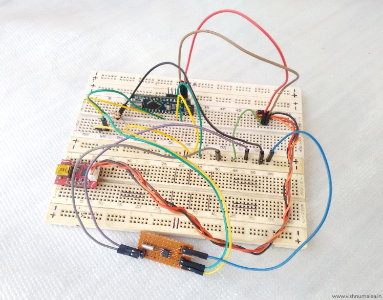 Good friend breadboard!
This would be the most interesting part of this project where you'll know how I ended up making a device that run for 50 years on a coin cell! I first protyped the entire circuit on a breadboard and finalized the design. I used a Li-Ion battery (3.6V) for testing purpose so as to save my brand new coin cells. I used my Fluke 87 True RMS multimeter for the current measurements. It has a 0.1 uA precision for the micro ampere range.
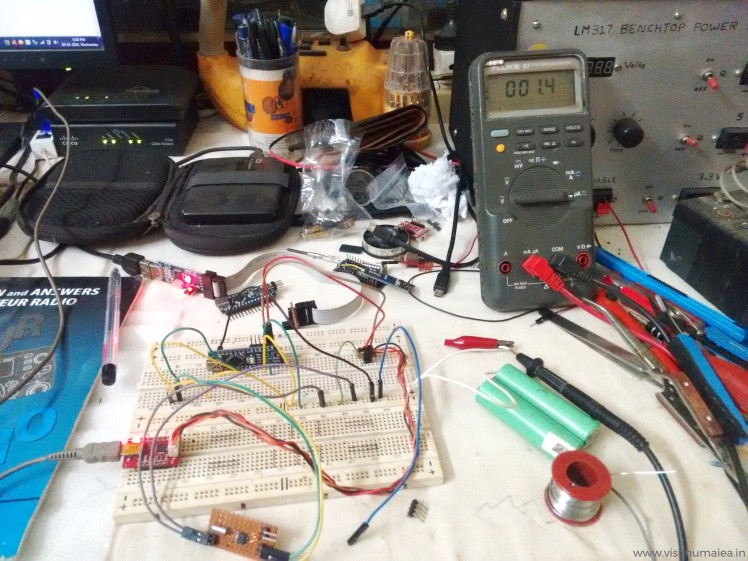 This is my table like when I was testing this - all basic stuff!
Let's see how we can put the Atmega168P into deep sleep mode and reduce the current consumption drastically.
noInterrupts (); //temporarily disable interrupts
set_sleep_mode(SLEEP_MODE_PWR_DOWN); // Choose our preferred sleep mode:
sleep_enable(); // Set sleep enable (SE) bit:
ADCSRA = 0; //disable ADC
power_all_disable(); //disables all modules
digitalWrite(LED_PIN, LOW);  //turn LED off to indicate sleep
interrupts(); //re-enable interrupts
sleep_mode(); //goes to sleep
As I've said before, this is the first time I used sleep modes in a microcontroller (MCU) because I've never needed it before. Most of the information related to AVR sleep modes was found from this forum thread and the AVR library documentation.
ATmega168P has five sleep modes.
-
SLEEP_MODE_IDLE– least power savings
SLEEP_MODE_ADC
SLEEP_MODE_PWR_SAVE
SLEEP_MODE_STANDBY
-
SLEEP_MODE_PWR_DOWN– most power savings
More info on the sleep modes can be found here and in this video. We're using the SLEEP_MODE_PWR_DOWN mode as you can see there. At this mode, the current consumption at 3.6V is only around 0.2 uA See the below graph from the ATmega168PA datasheet that shows the relation between active current vs supply voltage and power down current vs supply voltage.
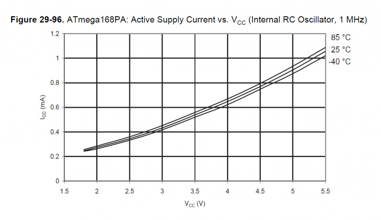 Around 0.5uA at 3.6V (we're using internal OSC)
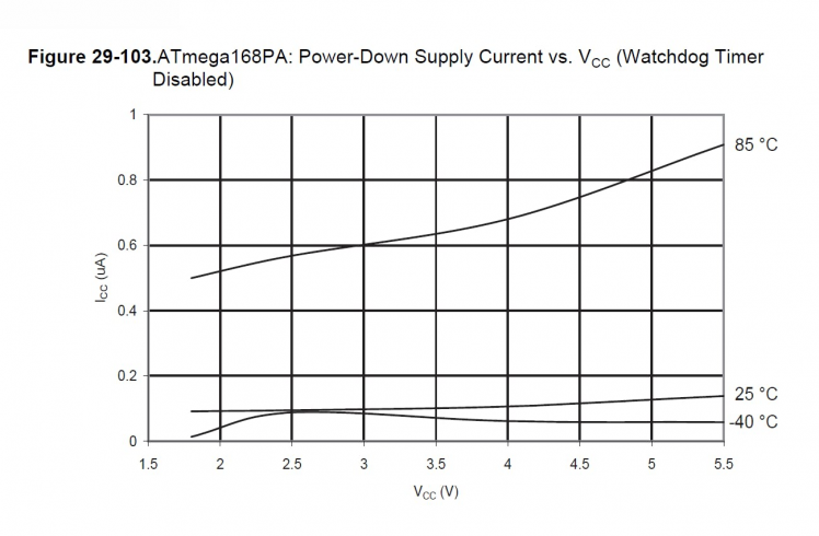 Between 0.1 to 0.2uA at 3.6V
Here's the actual reading of the current consumed by sleeping ATmega168P @1MHz.
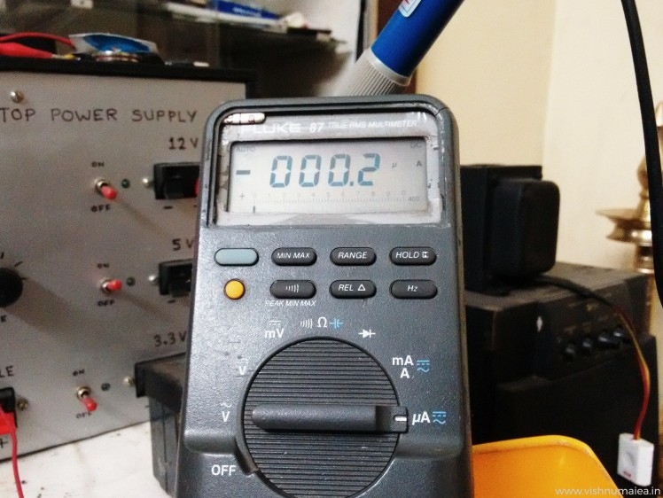 The minus sign is because I've connected the terminals in reverse
The value hops between 0.1 uA and 0.2 uA due to the lack of precision. But such a precise measurement isn't necessary but would've been interesting to see.
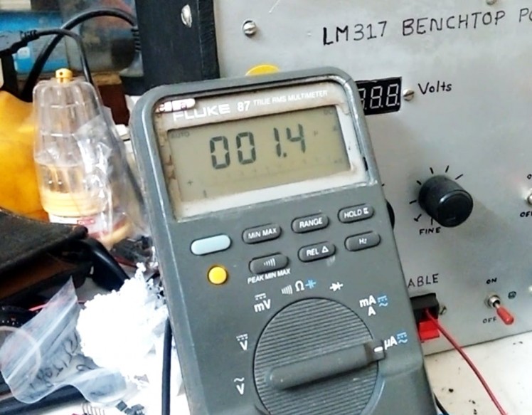
The power consumption of ISL1208 RTC at max is 1.2 uA. So if we add this with the power down mode current consumption of the MCU we get 1.2 + 0.2 = 1.4 uA. My meter measured between 1.4 uA and 1.6 uA which justifies the calculations. The variations is only due to the lack of precision and our approximation or rounding of numbers.
 Screenshot taken from the video below
Here's an unlisted video from my YouTube channel where I show the testing.
Shot on my Moto G2. Sorry for the low quality and the doge in the background.Now let's do the simple math to find how long we can the system on a coin cell. The CR2450N from Reneta has a nominal capacity of 540mAh. I have two red SMD LEDs on the system which consume about 6 mA (even with two LEDs) with when turned ON. So that's the peak current consumption of the device at worst. How long these LEDs light up can be summarized as,
1. As long as the time setting switch is activated while you're setting the time (but you don't have to do this every year)
2. The 6 second delay before sleep.
3. LED flashes on your birthday and stay ON for about 19 seconds.
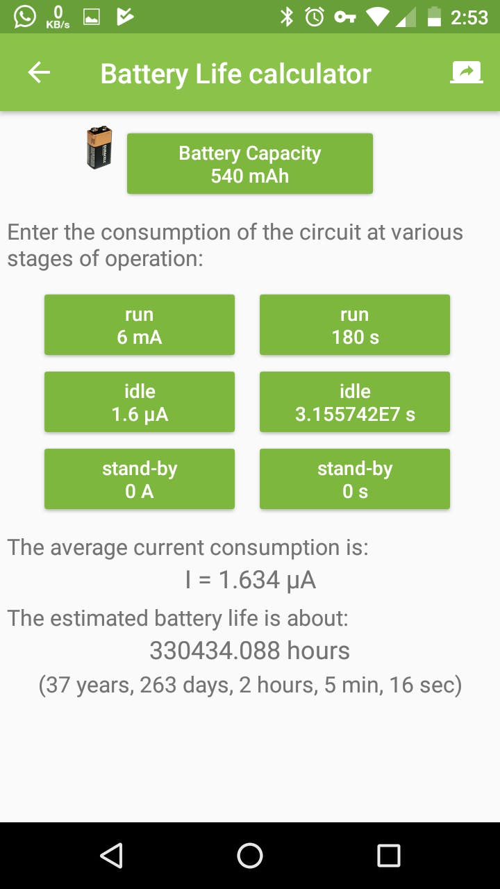
Let's not be accurate here but just make an approximation. Let's assume the time setting requires 2 minutes (LEDs will be ON for 2 mins) and and additional 1 minute ON time for other things including the birthday flashing. So it's total 3 minutes or 180 seconds for which the system consumes 3 mA current. Let's take the sleep or idle current as 1.6 uA, though it's lower actually. There's 31557600 seconds in a year of 365.25 days. If LEDs stay ON for 180 seconds in a year and OFF for (31557600 - 180) seconds, then the average current consumption will be,
Average Current = [((6 x 10^-3) x 180) + ((1.6 x 10^-6) x 31557420))] / 31557600
                     = (1.08 + 50.491872) / 31557600
                     = 51.571872 / 31557600
                     = 1.634 x 10^-6 = 1.634 uAh
If the average current consumption is 1.634 uAh, then the 540 mAh cell can run the device for:
Time Span (approx) = (540 x 10^-3) / (1.634 x 10^-6) = 330477.3562 hours
                         = 13769.88 days
                         = 37.699 years
Note than this approximation is do not consider self-discharge of the battery. It'll be taken into account later. You can also use the ElectroDroid app to calculate battery life. Here's a screenshot of the calculations we just did.
BUT WAIT...
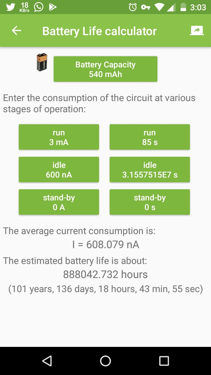
Can we reduce the current consumption further ? YES WE CAN! I made further optimizations to my design to limit the average current consumption to 0.6 uA, yes I did that. Not let's see what optimizations I did,
1. To remove the extra red SMD LED to reduce the current when the system is active/running. Before it was 6 mA at max with two LEDs. So with one LED, it'll be reduced to half, ie 3 mA.
2. To reduce the current consumption of RTC, we need to disconnect the VDD pin of the ISL1208 RTC from the VBAT pin. Previously the VDD pin was connected to the VBAT pin where I supplied the 3V from the cell (you can see this in the schematic). In that configuration, I also had the LOW_POWER mode bit (LPMOD) of the RTC set to 1 activating the low power mode. So now you might think if the low power mode is set, then the chip might be consuming the lowest current. But that's not the case when we have the VDD tied to VBAT. Because low power mode bit is only useful if we have VDD > VBAT all the time. At such situation, the RTC's internal power switch will select VBAT as power source reducing the current further by 600 nA when VDD >= VBAT (from typical 1.2 uA which I've mentioned before). But if we can run the RTC in VBAT only with VDD = 0, the current consumption can be reduced to the minimum ie, 400 nA as per the datasheet. So what I did is, first I disabled the low power mode by setting LPMOD to 0. Then added a jumper to the RTC breakout board to disconnect the VDD pin from VBAT when I don't need it. Why need the jumper is because, the VDD pin must be greater than or equal to VBAT in order for the I2C to work. So I can connect the jumpers when I need I2C while I'm setting the time, and can disconnect it after. This will let the RTC to consume the targeted 400 nA current. Tada! We did it!
 Here's what the ISL1208 datasheet says about the low power mode - warns about the I2C problem. I encountered this once
Here's the current consumption test video after the optimizations and mods.
If we put those new values to the ElectroDroid's battery life calculator, we get, 101 years and 136 days. A theoretical operating time of more than a century! The average current consumption is now only 608 nA. Here's the screenshot.
Okay, What's the actual operating time ?
Batteries aren't perfect, nor anything we design. So let's also consider the 1% self discharge of the cell into account.
1% of initial capacity of 540 mAh CR2450N = 5.4 mAh
Self-discharge current = 5.4 mA per year or 616.4 nAh (5.4 mA / hours in a year)
Adding this 616.4 nAh with the 600 nAh sleep current = 1.216 uAh
Expected operating time with average current of 1.224 uAh = 50 years, and 131 days.
That's the actual operating time if the cell will be fine
Here's a table of actual operating times of different types of coin cells with the 1% self-discharge of initial capacity every year.
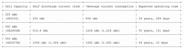 *Average current is calculated with 3 mA active current and (Isd + 600 nA) sleeping current and doing the same math we previously did.
The main practical concerns associated with running the device for such long periods are,
1. Will the battery retain the charge and voltage for that long ?
2. The effects of environmental variations on the circuit and battery performance.
3. And you screwing up things! XD (don't drop it, chew it, sit on it, run your car through it or launch it into space!)
Coin cells are usually made to last for 10 years, which is their shelf life, and some even last longer than that. But that doesn't mean they'll start to disintegrate to an useless state after that. If the cell is physically fine, it can still power things. As per Renata >this datasheet from Energizer, that 1% figure is of the fresh capacity. Below is a chart that shows the standard discharge time in years (this doesn't consider the self-discharge or other exceptions). It clearly shows the theoretical expected operating time is way too longer than 10 years.
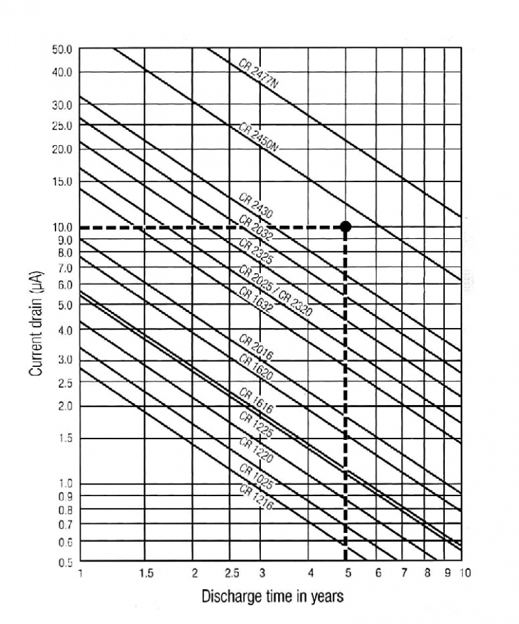 Source : Renata
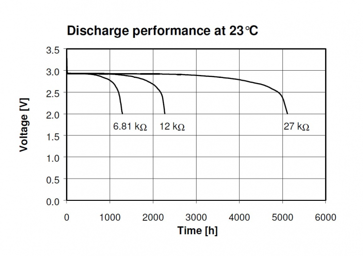 Discharge performance of CR2450N. Source : Renata
Self-discharging not only reduces the capacity but also reduces the voltage. Both ATmega168P and ISL1208 are designed to be operated fine at voltages as low as 1.8V. So the reduction in voltage might not be a problem. You can learn more about running systems with coin cells here.
To ensure long operating span, we must make sure the device is properly concealed against much of the environmental changes such as temperature, humidity, corrosion etc. These are some things you can do to protect your circuits,
1. Coat the PCB with long lasting conformal coating.
2. Place a pack of silica gel inside the enclosure.
3. Seal the enclosure with less temperature conductive materials and make it air tight.
4. Place it somewhere safe from naughty hands!
Step 10: Building
I used a perfboard to solder everything as per the schematic. I used berg connectors for the battery, switch and LED so that it'll be easy to remove them if needed. Below are the some images of the PCB.
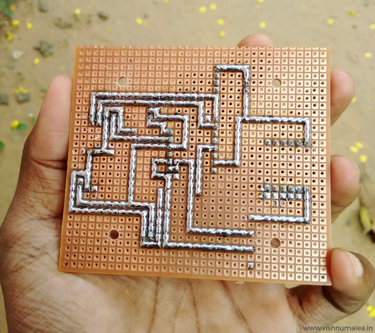
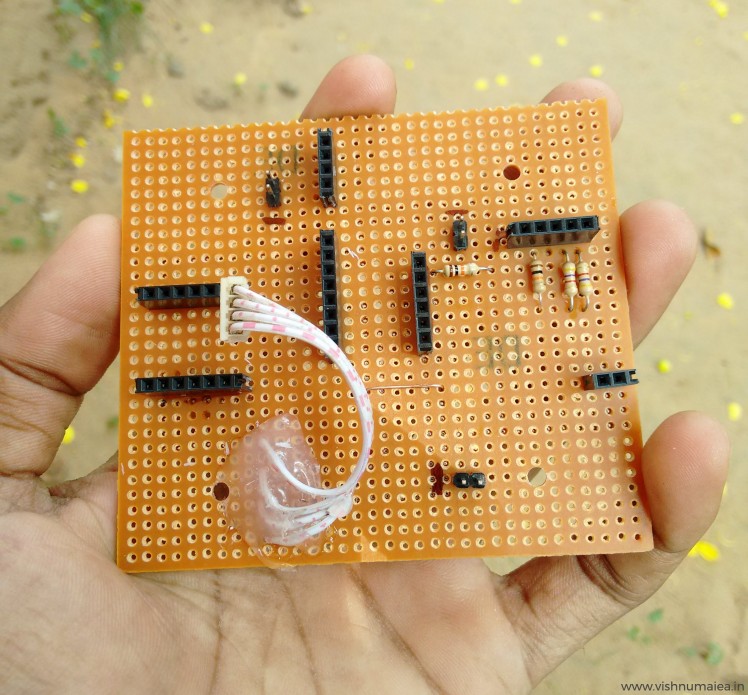 One jumper was needed
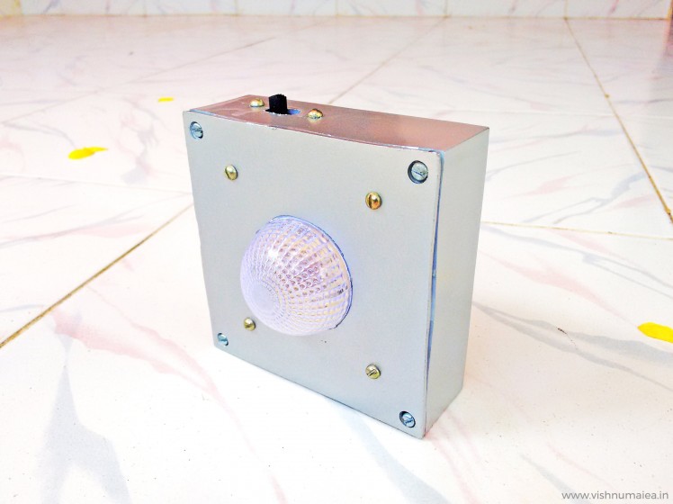
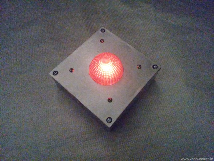
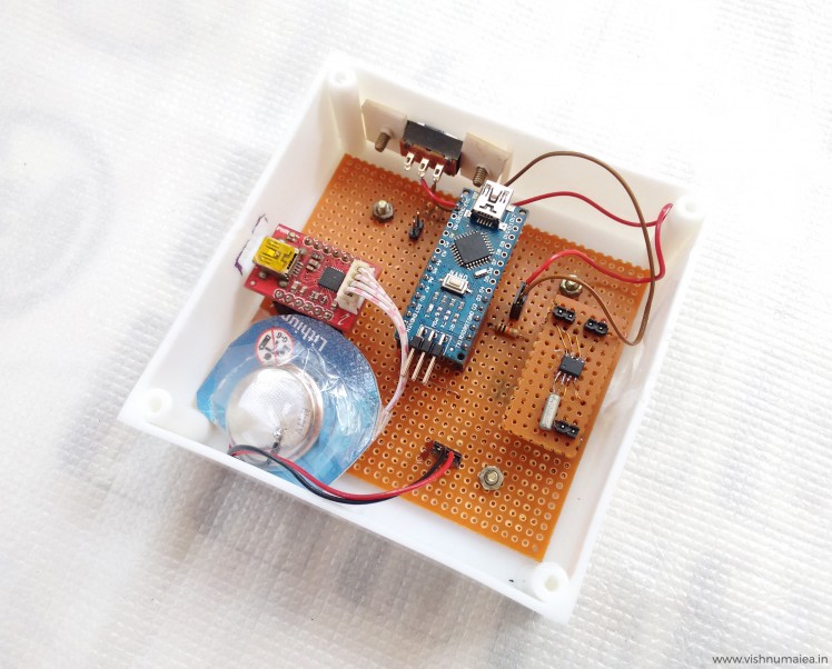
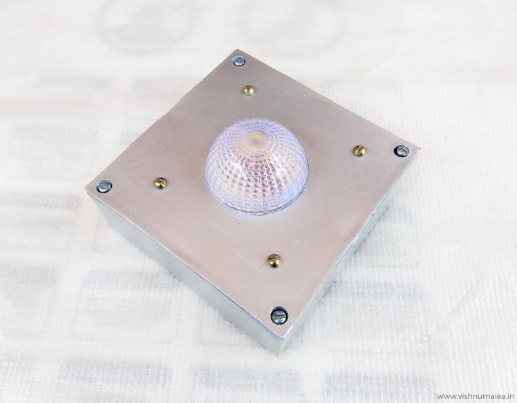
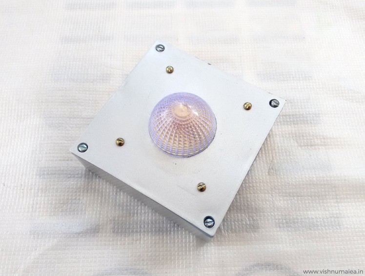
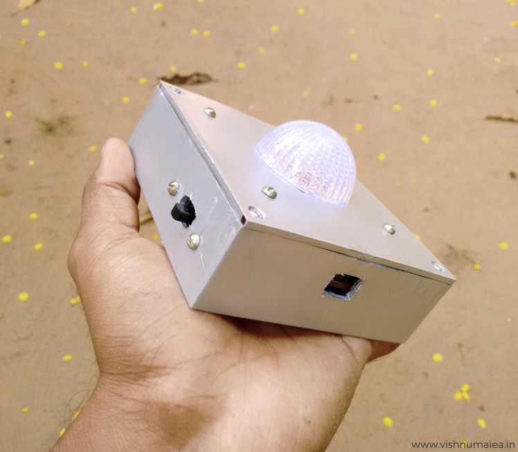
To build the enclosure I used a 4" x 4" switch box which I bought from an electrical shop. I made two rectangular holes for the switch and USB. You can 3D print an enclosure if you want; sadly I don't have one. The dome was snatched from a cheap LED light and used super glue to fix it on the box. I painted it with silver spray paint.
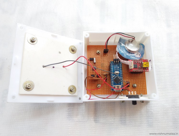 Modular design
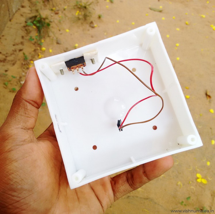
 The LED
Use your ingenuity to build it.
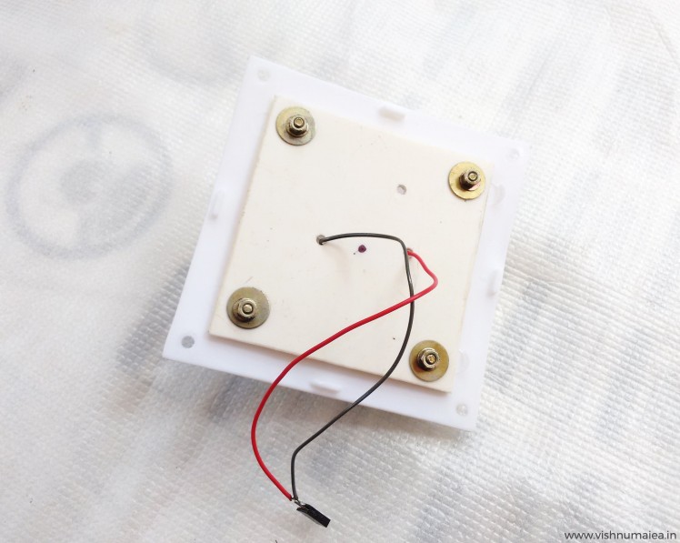 Top cover
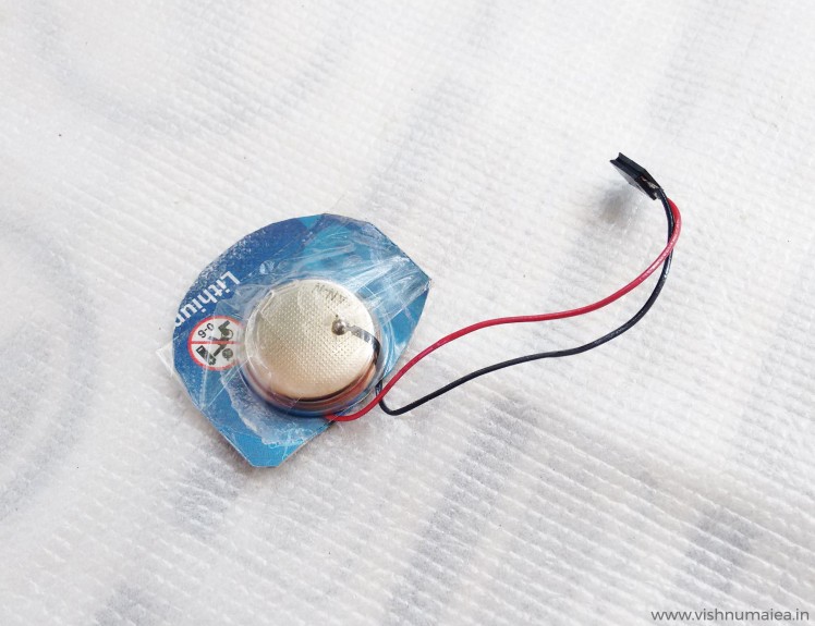 Simply the battery - CR2450
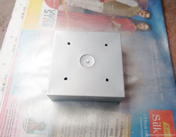 Painting
 It needs some decorations I know
What missing is some decorations. I'm not good at decorating things. If you are going to gift this to someone, you know what to do.
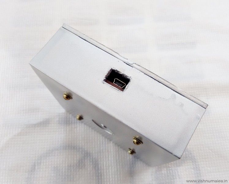 USB
USB
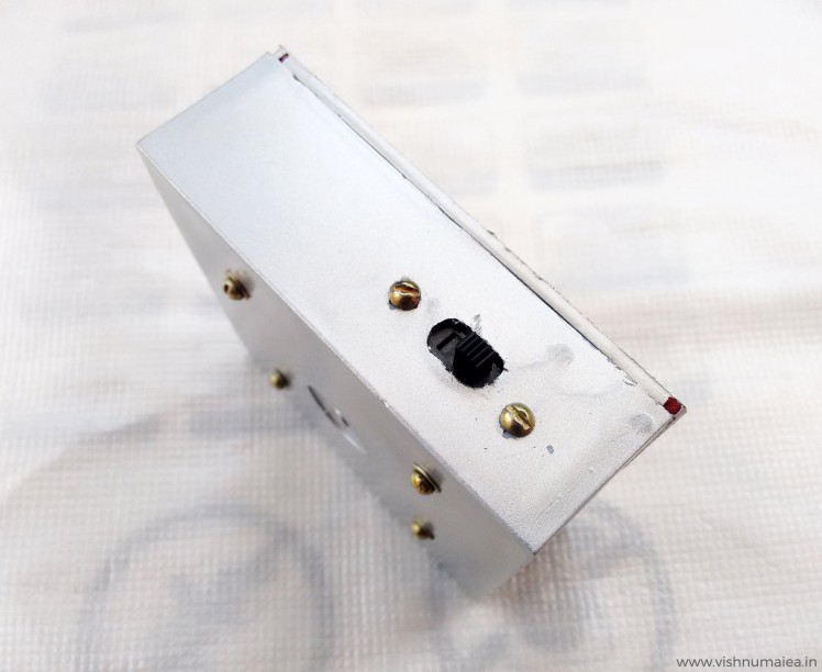 Time Setting Switch (SPST)
 Not the best paint job
The final output is satisfying to the extend of my hardwork. I might find someone else to decorate it.
Step 11 : Improvements
There's always room for improvement. Some of my suggestions are,
1. Using a Nokia 5110 LCD with or instead of the LED bulb. The LCD controller only consumes a couple of 100 uA at normal operating modes without the LED backlighting of course. Monochrome LCDs only consume extremely low currents. So using it would be better than a flashing LED, where you can actually print the happy birthday message on the screen itself. I might do this in future because I have couple of them lying around here.
2. A software that runs on the computer that'll set/sync the time accurately and automatically. I'm thinking of developing a simple one using Processing.
3. Flashing the LEDs to indicate the current age - for example if it's your 5th birthday (OMG are you're reading this ?!), it'll flash a sequence for 5 times. Currently you can not set the current age in the system. You may add this.
4. Designing a dedicated PCB in eagle (planned).
5. If blinking LED isn't your thing you can actually make this more exciting with for example using an opto-coupler you can turn on an AC alarm, music player, lights or anything you want to blink, move and scream on the birthday of the one you wish. You can even exclude the microcontroller and only use the interrupt from the RTC. Everything's possible!
So what are you waiting for ? Make one, decorate it with stickers, color papers, glitter or anything and gift to your loved ones or even yourself! And tell them to wait for this magical device to wish them happy birthday.
What you see here is actually a prototype of a device that'll refine and release in future. So stay tuned. Please feel free to share if you have found any errors with this documentation or have any improvement suggestions. Happy making :)
Schematics, diagrams and documents
Code
Credits
Related products


Leave your feedback...