

Average Speed Head-up Display Unit - Giantboard

Made by Al / Automotive / Bikes / Vehicles
About the project
GPS to HUD for in-car use. To make sure a road's average speed cameras do not send you a letter in the post!
Project info
Difficulty: Moderate
Platforms: Linux
Estimated time: 5 hours
License: GNU General Public License, version 3 or later (GPL3+)
Items used in this project
Hardware components

Software apps and online services
Hand tools and fabrication machines
Story
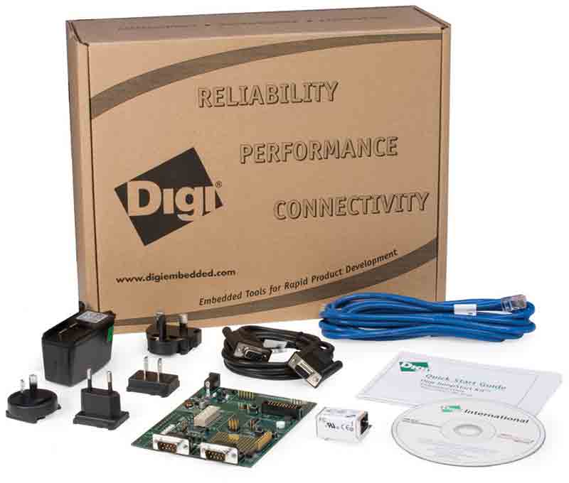
Giant Board arrived 14th April 2020.
Someone else was having loads of trouble so I measured the current consumption of a bare Giant Board with an 8GB SD inserted. During the two minutes or so it took to boot up, the 5V USB current varied from 30mA to 80mA according to my Thurlby PSU's meter, subsequently discovered to be somewhat innaccurate.
The LEDs showed this:
Green: Fully on, showing power.
Yellow: Flashes at about 4Hz during first 25 seconds of boot-up.
Orange: Intermittent flashing. After boot-up, very brief flashes at 1 second intervals then brighter flash at 30s intervals.
GPS/GNSS Average Speed HUD - Giant Board project
Average speed-limited areas are now more common, both along stretches undergoing road maintenance and there are also permanent areas, one of which is on the road to the Office!
Cars and sat-navs indicate current speed, but not average speed. HUD means head-up display or heads-up display and the original plan was to reflect the display off the windscreen. Speed data comes from a satellite navigation receiver. Originally called GPS but it is now referred to as GNSS (Global Navigation Satellite System), which covers GPS, GLONASS, Galileo, Beidou etc. I have mostly used the term GPS because this project happens to use a very old receiver!
Components:
a. GNSS/GPS receiver
b. Giant Board
c. SSD1306 128x64 pixel OLED 3V I2C-bus display
d. DIP switch
e. Press button
f. NPN transistors (2), LED and some resistors.
g. micro-USB power/data lead.
h. FTDI232 module
I. 9-way D-type connector if required.
Component Notes:
a. GNSS/GPS receiver. I happen to have bought a Garmin GPS18LVC puck-style one at my local radio club's junk sale, therefore it was used.
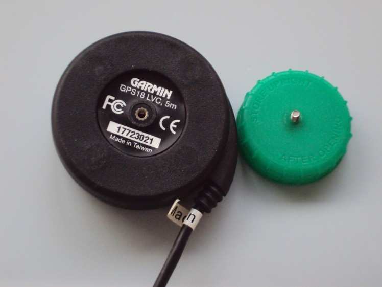
There are better choices available e.g. the smaller PCB-mounted devices with integrated antenna are ideal providing they offer serial data with TTL levels, and can be powered from 3.3 or 5V. The 4,800Bd data from my Garmin is similar to RS232 but without the +/- 12V voltages therefore it requires inverting to get the correct resting logic high state, hence the two transistor interface. My transistor interface circuit also reduces the 5V signalling levels from the GPS receiver down to 3.3V with a potential divider.
For a previous project, 'Teddy in Space' (HAM-1 hab), we used a Lassen receiver connected to an Arduino.
Other receivers may not require inversion and/or voltage reduction.
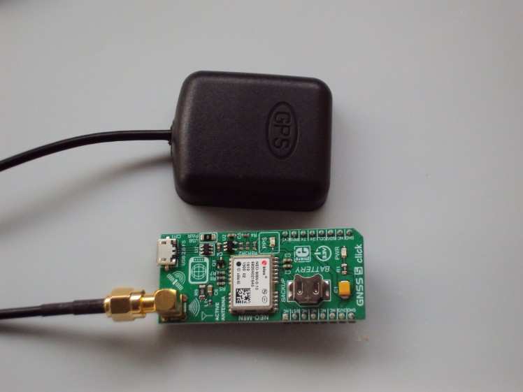
I have experimented with a GNSS 5 Click Board (shown above) and an external active GPS antenna; it works very nicely. With only a micro-USB lead between the Click board and my PC, to provide both power and data, I could immediately get serial data at a default 9,600Bd on COM6: using Putty. It streams default sentences, but not the GPRMC one that I use on the Garmin. Because the Click board is a GNSS receiver it uses slightly different sentences, so GPRMC is renamed GNRMC. Its GNRMC sentence has an extra comma towards the end, so I have modified my software GPS_AV1.py accordingly and it will decode both. Oddly its speed reporting is not zero but dithers around 0.02kts when the antenna is stationary. Another comparison between receivers is that the Click board reports speed with ten times the resolution. The Click board may need setting up to decode the other satellites. I have yet to try that, and I have not trained the Click unit to send just one sentence.
A test this morning shows the Click board takes under 10mA at 5V.
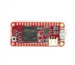
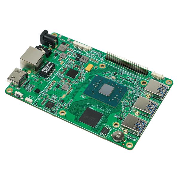
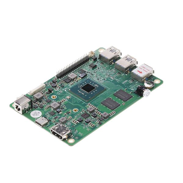
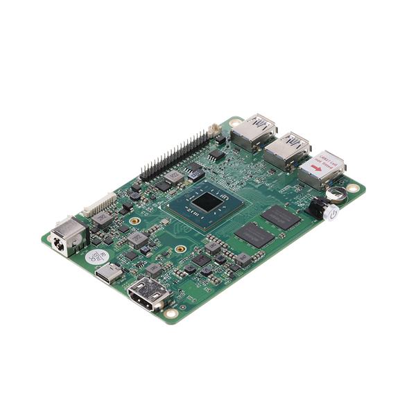
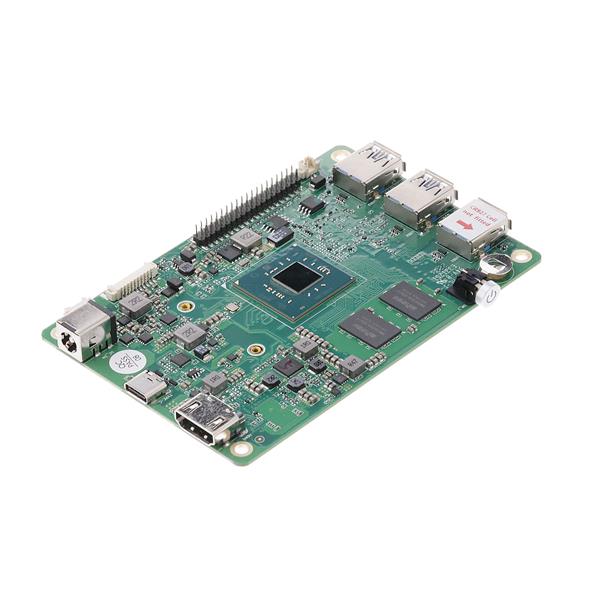
b. Giant Board.
This requires an SD card with a special image containing an ATSAMA5D27 version of Debian/Blinka/CircuitPython. Note that no connectivity via Wi-Fi/Ethernet is catered for in my project, therefore I use the software that came on the SD-card image exactly 'as-is', giantboard-debian-9.7-1GB-1-17-2020, and no extra library code has been added. I have also not attempted to modify the Linux kernel.
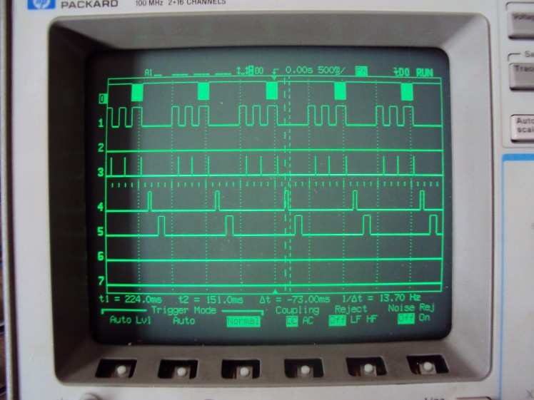
The Giant Board’s SD card is used for booting and logging all GPRMC data, its I2C port drives a display, its secondary UART gets GPS data and two digital inputs are used for switches. Digital outputs are used for testing. Here is a photo of my MSO showing these digital outputs being toggled as various software methods run in relation to GPS data, the top trace:
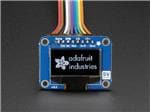
c. SSD1306 OLED. The 128x64 blue monochrome display seems to work nicely and consumes very little power. It has an internal 3 to 5V inverter and the adafruit_ssd1306 library code is happy, using default settings, to initialise the board's internal registers including the inverter controller.
For a previous Raspberry-Pi-based teleprompter project I used PyGame which was great as it allowed a display surface to be flipped and rotated. However the built-in libraries for the SSD1306 do not appear to do this, so I added my own large character fonts and python code to write pixels directly to the frame buffer either normally or in reflected mode. These fonts are available from here: A link to Fonts etc
Unfortunately, experiments have shown that the OLED is simply not day-readable when reflected off a car's windscreen; it is just not bright enough. A UK source of OLED displays is plusopto.co.uk
To make a reflected display appear at infinity requires a small lens but I have not investigated this. It would need some careful thought to prevent sunlight from setting fire to the OLED...
d. DIP switch. This selects normal or reflected display mode. The CPU has internal pull-up resistors but the built-in libraries do not give access to this facility so external pull-up resistors are fitted as that is considerably easier to do as opposed to trying to fork the kernel. Only one section of my dual-switch is actually connected. The spare half is for 'future-proofing'.
e. Press button input. This multi-function button is used to clear the average speed accumulators, select average or current speed, and exit the program. Once the program has stopped, power can be removed or a PC connected perhaps to copy log files to its SD card's /boot/uboot, or software changes made and the program re-run. Again, an external pull-up resistor has been fitted. The push button may be duct-taped to the gear stick.
Originally the push button had two functions: if held for 5 seconds or more it clears the average speed.
If held for 10 seconds or more, it stops the program. But it was found on a test drive that displaying one's current speed to 0.1mph resolution could be another useful feature to add, because the car's (mechanical) speedometer accuracy is ultimately dependent on tyre/tire diameter, air pressure, temperature, a spring and a magnet.
My Button Logic is now: press and release for approximately half a second to clear average speed. A press and release over about 2 seconds toggles average to current speed display, and a hold down for >10 seconds hold exits the program.
f. Transistor interface. This is only required for serial data inversion and/or >=5 volt signalling. Often one can safely apply 5V signal levels to some I/O pins, via current-limiting resistors, as for example most 3.3V PICs have some 5V-tolerant input pins. Alas, the ATSAMA5D27 data sheet does not mention this. The transistors chosen were NPN types BC337 because they were in the junk box, but of course anything similar will work as they are not critical.
h. FTDI232 module. This item is optional. I added an FTDI232 module so that the Linux boot process could be monitored. The module converts 3.3V serial data from the Giant Board’s TX pin (ttyS0) at 115200Bd to USB, and my PC sees it as COM5. It is not required for normal operation. The RX pins is not connected.
Construction.
The project is built on a piece of Veroboard(tm) and some of the Giant Board's edge pins were wire-wrapped to strip-pins soldered onto the perf-board. This allows modifications to be made without needing to de-solder. All other components were soldered onto the Veroboard. My GPS cable happened to have a male 9-way ‘D’ connector, so I used a 9-way female connector as a convenient way to plug and unplug for testing. The wiring was non-standard. There is often confusion as to the sex of ‘D’ connectors. If a connector has 9 pins then I call it male.
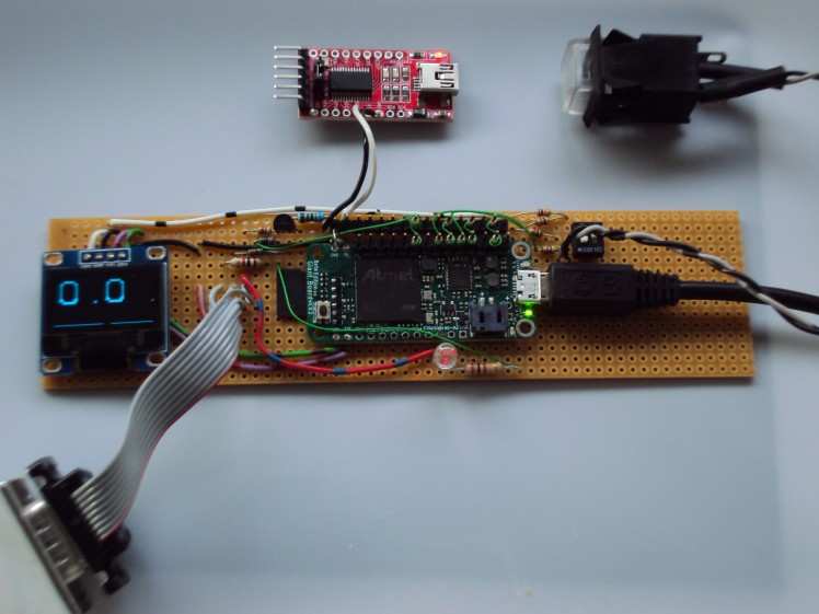
Eagle-eyed people will notice the lack of a driver transistor on the Veroboard implementation. My original interface was built in bird’s-nest style, in the ‘D’ connector’s shell. But that didn’t look neat. As I had set-up the GPS receiver already, I did not put the extra components on the Veroboard to save space.
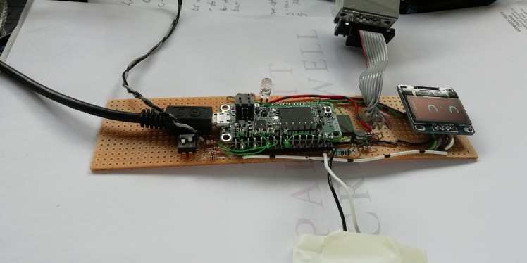
Viewed from the top:
Software Details.
This project takes an NMEA sentence, specifically the GPRMC one, from a GPS receiver and decodes current speed, averages it and displays the result on an OLED display.
The Garmin's default settings cause it to send loads of different sentences over a two second cycle. We only need one sentence so a Python script, GPSSetup.py, was written to allow the user to train the receiver to only send out one particular sentence at a much more useful one-second update rate. This is achieved by clearing all sentence reporting and enable the required one, GPRMC. Of course this could be automated in the main program but to make life easier I decided that, because it only runs once, use a separate Python script. The GPS receiver's NV ram stores the settings.
All code is here: https://app.box.com/s/8e6okfii3m20sz3rgg7s5ogb9pfs8nye
More modern receivers may not offer the GPRMC sentence but there will be an equivalent e.g. GNRMC, that outputs date, time, lat, long and speed. It is very easy to modify this program as required. All the relevant information on each field is freely available on-line.
It took the Giant Board about 2 minutes 30 seconds to boot up its Linux OS. To reduce this try:
sudo systemctl disable connman-wait-online.service.
I have modified /etc/rc.local to call my GPS_AV1.py software on power up so a keyboard is not necessary. That is the *nux equivalent of Autoexec.bat. This starts the app in about 27 seconds.
Here is rc.local
#!/bin/sh -e
python3 /home/debian/GPS_AV1.py &
exit 0
Conversely, in order to run the program from the Gadget Port's terminal (ttyGS0), type this from Putty on your PC, obviously once you have logged in first(!):
sudo python3 GPS_AV1.py
Because the program uses hardware features it must be run under sudo. When the program starts, its software version 'AV1' is displayed on the OLED for a second.
After setting up the UART and I/O pins, the main program then waits until the GPS unit replies with valid data. GPS serial data is fed from the Garmin via a transistor interface into the Aux serial port /dev/ttyS1 on pin AD3. Even though the Giant Board has pins marked TX and RX, this port /dev/ttyS0 is only useable to display Linux boot output, at 115kBd, and cannot be used to receive data due to permissions errors. Unfortunately the kernel would require forking to sort that issue out.
The OLED initially shows GV which means no GPRMC block and Invalid data. Here is a typical GPRMC sentence, note the status is 'V' which means Not Valid(!?!):
$GPRMC,093812,V,5103.6172,N,00018.1755,W,,,270420,002.5,W*65
It may take a few more minutes for the first fix data to become valid.
Now this is a valid sentence; status is now 'A':
$GPRMC,155022,A,5103.6184,N,00018.1797,W,000.0,019.8,010620,002.5,W*7A
For comparison, the Click Board's NEO-M8N module replies:
$GNRMC,153523.00,A,5103.62214,N,00018.17904,W,0.021,,160620,,,A*7B
The main reason to use the Giant Board, as opposed to perhaps a PIC, is the ability to use Python3. A few lines of that can do loads of useful work, and one does not have to worry about cross-compilers, (in)correct libraries etc.
The incoming valid GPRMC sentence is read by this line:
- line_in = tty1.readline() # get the sentence
The data (in CSV format) is split by commas. This is one of the many very powerful Python functions and makes life so easy!
- str_in = str (line_in) # convert to a string
- data = str_in.split(',') # split at each comma
- speed = data[7] # for example, this is speed.
It doesn't get easier than that! Those 4 lines of code are the nuts and bolts of the software. Full code is to be found at the end of this story.
Speed is accumulated in spd_acc and a number of samples counter, spd_ctr, incremented. Because Python3 doesn't care about an object's length (i.e. byte or word or long) this number can get larger and larger; it will still work, yet another advantage of Python.
Invalid blocks do not get counted e.g. when in a tunnel. GPS speed info comes in as a 4 digit floating point number starting at 000.0 in knots. Thus it is quite accurate and is even useful at walking speeds. GNSS receivers such as the Click's NEO offer even higher resolution.
In Run mode, the main loop runs every 200ms, very approximately. The 200ms consists of a non-blocking 100ms wait time for serial data and a 100ms sleep time at the end of the loop. I used my HP MSO to see how long each method took by bit-banging output pins, and the data splitting etc. takes 50ms and the oled.show() method takes 100ms.
The OLED displays 3 large digits and will show walking speeds to a resolution of 0.01mph or driving speeds to 0.1mph below 100mph. Sadly I have not been able to test above a ton. The decimal point moves automatically. My fonts are on a 32 bit x 32 bit matrix. To fit the OLED's 64 pixel height. I scale each character in the disp_txt method. That method writes pixels either normally or inverted.
Each time a new average speed sample is displayed, a moving line of 64 pixels is rotated clockwise around the display's border. A video of this is here: YouTube link to Average Speed display
Then it is possible to know if GPS updates have stopped or Linux has gone AWOL. When the current speed mode is operational, the border toggles between two vertical lines or two horizontal lines so it is immediately obvious whether the display is showing average or current speed. A video of this is here: YouTube link to Current Speed display
As another feature, each incoming sentence is logged on the SD card in the directory /home/debian/logs. The log filename is taken from the GPS date, so up to 24 hour's worth of data can be appended to one file. That limits its size to a sensible level. Invalid blocks are also logged, but to a different file; the filename has an ‘x’ appended to the date.
Now when plugged into a PC, via the USB Gadget serial port, the SD card is visible as /boot/uboot. If Putty is used on that PC, at 115,200Bd, one can use the terminal and copy log files over from /log to the common /boot/uboot directory. The uboot directory has a size of about 40MB and that is more than adequate to transfer a single day's log because they cannot get that large. A spreadsheet programme running on the PC can then plot all sorts of useful stuff about the day's trips by simply importing this CSV data.
Current consumption of the Giant Board, Garmin receiver and OLED varies from 80 to 100mA during the boot process and may be powered from a car's cigar lighter socket with one of those USB power adaptors. Conversely a 5V/4000mAh mobile phone power bank works well and has the capacity to run the project for several days continuously. This means a back-pack person-portable version is feasible.
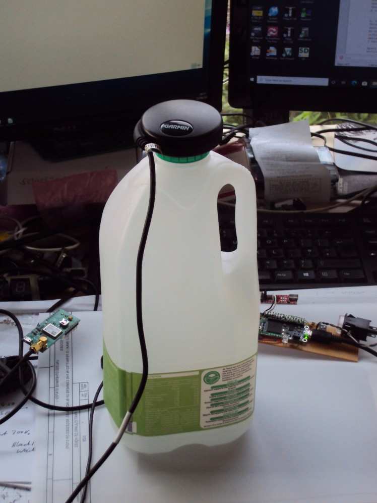
At the start of this project, we were having restrictions on car use that limited one to essential journeys only, so for testing purposes a back-pack version was built so I could take a hike and test the software for bugs. This worked really well and my average walking speed was 3.71mph.
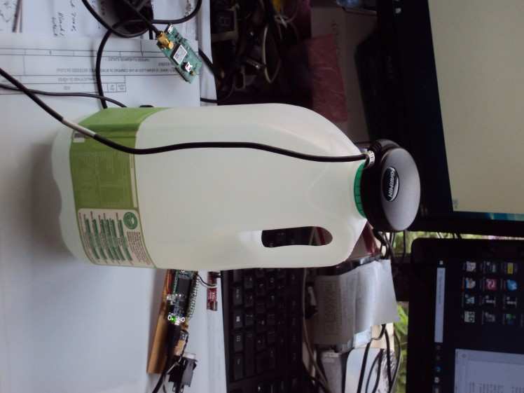
To keep the puck upright I modified a polythene 2.272L/4pint milk container which could then be placed inside a rucksack. A short (5mm) M3 bolt holds the GPS puck onto the lid, then the lid is screwed back onto the container. This could also be used by cyclists. Note my board sitting on the right hand side and Click GNSS module on left.
Conclusions.
The use of Python3 is very powerful and enjoyable to learn. A few lines of Python can do lots of work. I have not written the code in 'Pythonic' language so it may be easily understood and modified by all. Debug info can be printed from the program via the Gadget serial port. The software starts with
- Debug_mode = False # could be True to print debug messages
My program was typed in with Nano, as it is not that long, under 300 lines. Home-made font files were copied over from a PC using the boot directory. The Giant Board plus OLED take only about 80-120mA from the USB power supply during boot-up, and the current drops dramatically once my app starts. It then takes only 60mA with no GPS device attached, and 130mA for the Giant Board, OLED and GPS. My loop ends with
- time.sleep(0.1)
and that may well power-down the CPU to its 200uA figure. (Figures supplied by Groboard seem to show minimum power is over 20mA)
On the downside, a boot time of 27 seconds is not very good. I know that some versions of embedded Linux can boot in 10 seconds but whether that is from an SD card or not I don't know. But the USB gadget port needed yet another 60 seconds before the login prompt appeared. That one is not yet sorted...
The lack of being able to use the pins TX and RX is worth fixing. The inability to enable internal pull-up/down resistors is not ideal especially for any large quantity production – resistors cost money! Again. these issues require forking the kernel I believe.
There are some notes by Microchip on using the various interfaces under Linux, but the CAN bus is not there.
Finally, the HUD mode has had to be abandoned due to the lack of visibility of the OLED. But if the OLED is placed in front of the windscreen it is easy to see. For a proper HUD it really need 3 high-brightness LEDs but there are not enough I/O pins on the Giant Board to run segments individually. I try to avoid multiplexing large currents because of the EMC problems that can be caused. One alternative is to use three latched 7447 BCD to 7-segment decoders and wire the LEDs up for an inverted display. That would need 7 I/O lines. But there is no easy way to invert the display should that be required.
A more elegant solution would be to drive the 3 LEDs from a 40 or 44-pin 5V PIC. The SPI port could communicate to the PIC. Then software could be used to invert the display and brightness could be controlled via PWM.
Many years ago I have used an MM5450 34-output LED driver and thought they were now obsolete, but a swift look at Farnell's website has proved me wrong, and they are still manufactured by Microchip. But the PIC solution would be very slightly cheaper.
The software has now been improved after many miles of testing. My GPS receiver is confused by heavy foliage and that results in invalid data blocks for up to 2% of the journey. The ability to see the 'V' displayed is handy; before that change was made, the display mysteriously froze for about 20 seconds, because sync was lost, and now I realise why that was.
The code for GPSSetup:
- #! /usr/bin/python3
- # above line is 'shebang line'
- # GPS Test Program
- # GPSX1.py APRW 29-04-2020
- # set Garmin to output only GPRMC NMEA sentence.
- # read data
- # generate average speed
- # display average speed
- # Gadget Port commands:
- # c = clear av speed
- # m = monitor GPS input
- # wr/w1 = write to GPS unit : r reset output/ 1 = allow RMC only
- # n = no monitor output
- # gga = send GPGGA sentences
- # gsv = send GPGSV
- # rmc = send GPRMC
- # f = flush input
- import serial
- # no module called: import getch
- sv_speed_kts=0.0
- av_speed_samples=0
- av_speed_acc=0.0
- def clear_av_speed():
- av_speed_kts=0.0
- av_speed_samples=0
- av_speed_acc=0.0
- print ('Averages cleared.')
- def reset_GPS():
- # send $PGRMO,,2<cr>,<lf> to ttyS1
- tty1.write(b'$PGRMO,,2*75rn')
- print ('Sent $PGRMO,,2*75 cmd')
- def send_RMC():
- # send $PGRMO,GPRMC,1<cr><lf> to ttyS1 ( tty1)
- tty1.write(b'$PGRMO,GPRMC,1*3Drn')
- print ('Sent PGRMO,GPRMC,1*3D cmd')
- def send_GSV():
- tty1.write(b'$PGRMO,GPGSV,1*23rn')
- def send_GGA():
- tty1.write(b'$PGRMO,GPGGA,1*20rn')
- #main
- tty1=serial.Serial('/dev/ttyS1',4800,timeout=1)
- print ('GPSX1 GPS Average Speed Program. rnOpening ttyS1...%s' %tty1.name)
- run_mode=True
- tty1.flushInput()
- while run_mode == True:
- print('Enter cmd: c/wr/w1/m/n/x/X:')
- cmd=input() # renamed input from raw_input
- if (cmd=='x' or cmd=='X'):
- run_mode=False
- elif (cmd=='c'):
- clear_av_speed()
- elif (cmd=='wr'):
- reset_GPS()
- elif (cmd=='gga'):
- send_GGA()
- elif (cmd=='gsv'):
- send_GSV()
- elif (cmd=='rmc'):
- send_RMC()
- elif (cmd=='f'):
- tty1.flushInput()
- line_in= tty1.readline()
- print ('Input: %s' %line_in)
- tty1.close()
The above only has to run once!
And GPS_AV1.py (latest version with fonts etc is here: https://app.box.com/s/8e6okfii3m20sz3rgg7s5ogb9pfs8nye
- #! /usr/bin/python3
- # GPS_AV1.py
- # Font ses QBI 24-point bitmap to display average speed.
- # Hardware: GPS on serial UART and SSD1306 on I2C bus, button on IO port
- # Feed GPS serial data into AD3.
- # Wed 13th May 2020 APRW
- # Mon 18th May 2020 APRW Add digital in on AD4.
- # Tue 19th May 2020 APRW Add button on AD1, log data into logs directory.
- # $GPRMC,time,A/V,Lat,Long,spd, dir, date, offsets, csum
- # 0 1 2 3 5 7 8 9 10 12 # split
- # display is 128 x 64 dots.
- # DIP Switch inverts display for HUD mode.
- # Press button clears average speed if pressed for a second or so
- # Press button exits program if held for 10 secs or so.
- # Tue 2nd June 2020 APRW New feature: toggle average/current speed display.
- # Tue 2nd June 2020 APRW Press button mods to change mode.
- # Wed 3rd June 2020 APRW try time.monotonic to check loop time.
- # Thu 4th June 2020 APRW Manifest constant Debug Mode to
- # stop/allow debug print
- # Thu 11th June 2020 APRW Add state machine.
- # Thu 11th June 2020 APRW Try digital outputs.
- # Sun 14th June 2020 APRW getline() mods for split data. L.
- # Mon 15th June 2020 APRW Check input is GPRMC and has >=11 commas
- # Tue 16th June 2020 APRW Store valid data in one file, junk in another.
- Debug_mode=False
- import board
- import adafruit_ssd1306
- import serial
- import busio
- import time
- import binascii
- import digitalio
- from enum import Enum
- class ModeEnum(Enum):
- START = 0
- RUN = 1
- END = 2
- # convert offset to 32-bit mask as my font is not in bit order.
- # Each 32-bit font row is in byte order e.g.
- # ....**** **...... .**...** *....... (left to right pixels)
- # 0x0F 0xC0 0x63 0x80
- lut_dict={0:0x80,1:0x40,2:0x20,3:0x10,4:0x8,5:0x4,6:0x2,7:1,
- 8:0x8000,9:0x4000,10:0x2000,11:0x1000,12:0x800,13:0x400,14:0x200,15:0x100,
- 16:0x800000,17:0x400000,18:0x200000,19:0x100000,20:0x80000,21:0x40000,22:0x20000,23:0x10000}
- # These constants relate to my 36-pt font and 24-pt font in a 32 bit x 32 bit matrix
- FontBytesPerRow = 4
- FontCharPitch = 128
- FontRowsPerChar = 4
- FontBitsPerCharRow = 24
- FontTopMargin = 24
- FontCharScanLines = 16
- row_offset = 1
- # display one large character at a time, xpos 0 for top left.
- # siz = 2 is 2 dots in row and 2 in column expansion
- # siz = 3 is 2 dots wide and 3 high expansion
- # inv_bool is true/false to invert characters
- def disp_txt(ch, xpos, siz, inv_bool):
- fhfont= open("/home/debian/24REGA.RES","rb") # full path required
- res_offset = ord(ch) # find offset into font file
- res_offset -= ord(' ') # remove space as font starts at ch = 20h
- res_offset *= FontCharPitch
- res_offset += FontTopMargin # now we know exactly where to seek
- # read out 4 bytes at this file offset, as there are 4 bytes per dot row.
- fhfont.seek ( res_offset, 0 ) # 0 is SEEK from start of file
- dat = fhfont.read(FontBytesPerRow)
- ldat = int.from_bytes(dat,"little", signed = False) # convert to a long
- # print (hex(ldat)) ...uncomment to see what top row looks like
- for row in range (0, FontCharScanLines,1):
- if (inv_bool == True ): row = FontCharScanLines - row
- row += row_offset # to fit smaller characters centrally
- for col in range (0, FontBitsPerCharRow,1):
- if (ldat & lut_dict[col]):
- if siz==1:
- oled.pixel((col+xpos), row, 1)
- if (siz==2):
- oled.pixel(xpos+col*2 + 1, row*2, 1)
- oled.pixel(xpos+col*2 + 1, row*2,1)
- oled.pixel(xpos+col*2, row*2 + 1,1)
- oled.pixel(xpos+col*2 + 1, row*2 + 1,1)
- if (siz==3):
- oled.pixel(xpos+col*2, row*3, 1) # these could be a pythonic
- oled.pixel(xpos+col*2, row*3 + 1, 1) # rewrite
- oled.pixel(xpos+col*2, row*3 + 2, 1)
- oled.pixel(xpos+col*2 + 1, row*3, 1)
- oled.pixel(xpos+col*2 + 1, row*3 + 1, 1)
- oled.pixel(xpos+col*2 + 1, row*3 + 2, 1)
- dat = fhfont.read(FontBytesPerRow) # read another 4 bytes
- ldat = int.from_bytes(dat,"little", signed = False)
- fhfont.close()
- def disp_curspd(cspd, invert): # display current speed
- # toggle horizontal or vertical border on and off
- global edge
- # global size
- oled.fill(0) # clear display buffer
- fcspd = float(cspd) # to a float from 000.0
- spd = fcspd*1.15078 # convert kts to mph
- if (spd>0.0):
- spd_str = str(spd)
- else:
- spd_str = '0.00' # convert to string
- digits = len (spd_str) # how many to display
- # print (spd_str+' '+str(digits)) # debug only
- if digits>4:
- digits=4
- for i in range (digits):
- if spd_str[i]=='.':
- disp_txt(spd_str[i],30*i+21,size, invert)
- else:
- disp_txt(spd_str[i],30*i+6, size, invert)
- if edge>1:
- edge=0
- oled.line(0,0,127,0,1) # top line
- oled.line(0,63, 127,63,1) # bottom line
- else:
- oled.line(0,0,0,63,1) # left line
- oled.line(127,0,127,63,1) # right line
- # do later in state_machine 11-6-2020 oled.show() as it takes 100ms
- edge+=1
- def disp_av(acc, ctr, invert): # display average speed
- global edge
- x1=(0,64,127,63,0,0) # 4 tuples for edge border
- x2=(64,127,127,127,63,0) # so oled.line can be used to
- y1=(0,0,0,63,63,0) # draw the moving border
- y2=(0,0,63,63,63,63)
- oled.fill(0) # clear the display
- if (ctr==0):
- ctr=1 # prevent divide by zero
- av_spd_kts = acc/ctr # divide accumulator by number of samples
- av_spd_mph = av_spd_kts * 1.15078 # convert from knots to mph
- av_spd_str = str(av_spd_mph) # Convert float to string
- digits = len(av_spd_str) # how many digits to display?
- if digits>4:
- digits=4
- for i in range (digits):
- if (av_spd_str[i]=='.'):
- disp_txt(av_spd_str[i],30*i+21,size, invert)
- else:
- disp_txt(av_spd_str[i],30*i+6,size,invert)
- if (edge >5):
- edge = 0
- oled.line(x1[edge],y1[edge],x2[edge],y2[edge],1)
- edge += 1 # move the 64 pixel border line along for next time
- # in state_machine 11-6-20 oled.show() # display digits plus border line
- def log_data(date, strdata):
- logf = open('/home/debian/logs/'+date, "a+") # generate absolute path
- logf.write(strdata) # must be str not bytes...
- logf.write("n") # whack a newline at the end of each row
- logf.close()
- #
- # void main(void) # start here!...
- #
- i2c = busio.I2C(board.SCL, board.SDA)
- oled = adafruit_ssd1306.SSD1306_I2C(128, 64, i2c)
- oled.fill(0) # clear the display buffer
- # GPS serial data input on this port...
- tty1 = serial.Serial('/dev/ttyS1',4800,timeout=0.1) # timeout 100ms
- # operator push button...
- button = digitalio.DigitalInOut(board.AD1)
- button.direction = digitalio.Direction.INPUT
- # button.pull = digitalio.Pull.UP ! error not implemented !
- # button.switch_to_input(pull=digitalio.Pull.UP) ! ditto !
- # invert display switch on AD4...
- inv_sw = digitalio.DigitalInOut(board.AD4)
- inv_sw.direction = digitalio.Direction.INPUT
- PWM1_Out = digitalio.DigitalInOut(board.PWM1) # to time functions
- PWM1_Out.direction = digitalio.Direction.OUTPUT
- PWML1_Out = digitalio.DigitalInOut(board.PWML1)
- PWML1_Out.direction = digitalio.Direction.OUTPUT
- PWM2_Out = digitalio.DigitalInOut(board.PWM2)
- PWM2_Out.direction = digitalio.Direction.OUTPUT
- PWM3_Out = digitalio.DigitalInOut(board.PWM3)
- PWM3_Out.direction = digitalio.Direction.OUTPUT
- oled.rect(0,0,127,63,1) # a border...
- # Show s/w version on oled...
- invert = inv_sw.value
- size = 3
- edge = 0 # display rotating border when running using edge
- disp_txt("A",6, size, invert)
- oled.show()
- time.sleep(1)
- disp_txt("V",36, size, invert)
- oled.show()
- time.sleep(1)
- disp_txt("1",64, size, invert)
- oled.show()
- time.sleep(1)
- disp_txt("N",90, size, invert)
- oled.show()
- time.sleep(1)
- # flush GPS serial buffer as lots of stuff could be in queue...
- tty1.flushInput()
- time.sleep(1)
- spd_acc=0.0 # accumulate speed, kts
- spd_ctr=0 # count samples
- run_mode = ModeEnum.RUN
- oled.fill(0) # clear oled
- disp_txt("*",6,size,invert)
- oled.show()
- disp_mode=0 # for av speed (0) or current speed (1)
- button_down_ctr = 0 # see how long button is pressed.
- state_machine = 0 # split read data / print / update OLED
- str_in='' # clear line in so it can be concatenated
- while run_mode == ModeEnum.RUN:
- if button.value == 0: # first of all check the push button
- button_down_ctr += 1
- # print (str(button_down_ctr))
- if button_down_ctr>=30 : # 10 seconds - ish! 3 loops per second
- run_mode = ModeEnum.END # end program if button held for > 10 secs
- oled.fill(0) # clear the display
- oled.show()
- else:
- if button_down_ctr>0: # had been pressed so check time
- if button_down_ctr<3: # under 1 second so clear average speed
- spd_acc=0
- spd_ctr=0
- if Debug_mode: print ("Clr...")
- elif button_down_ctr>=6: # 2 seconds at 250ms per loop - ish!
- disp_mode^=1 # XOR current speed bit
- if Debug_mode: print ("Disp"+str(disp_mode))
- button_down_ctr = 0
- # end of read button section.
- # Now see if serial data sentence in from GPS unit...
- if state_machine == 0:
- PWML1_Out.value = True # time the function
- line_in = str(tty1.readline())
- PWML1_Out.value = False
- if len(line_in)>1:
- PWM1_Out.value = True # time when data rxd
- if Debug_mode:
- disptime = time.monotonic()
- print('d')
- print (disptime) # see how long sections take to run
- print (line_in)
- str_in=line_in # no need to concatenate
- if len(str_in)>60:
- if str_in.find('$GPRMC')>0: # or str_in.find('$GNRMC')>0: # or GNRMC of course!
- state_machine = 1
- else:
- str_in='' # clear and start again
- PWM1_Out.value = False
- elif state_machine ==1: # we have got a sentence so split on commas
- PWM2_Out.value = True # time this function with MSO
- invert = inv_sw.value
- line_in=''
- # print ( str_in) # uncomment to print all GPS info to GadgetPort
- # print ('commas='+str(str_in.count(','))) # should be 11 commas
- if str_in.count(',') < 11:
- oled.fill(0)
- disp_txt("C", 6, size, invert) # 'C' means comma count error
- state_machine = 2 # display it
- else:
- data = str_in.split(',')
- if data[2]=='A': # A=valid data
- spd_acc+= float(data[7]) # speed in knots from GPS
- spd_ctr+=1 # (1 second per) sample
- if disp_mode & 1:
- disp_curspd(data[7], invert)
- else:
- disp_av(spd_acc, spd_ctr, invert)
- state_machine = 2 # display on next loop
- log_data(data[9], str_in) # log good blocks here
- duff_data = False
- # log_data(data[9],str_in) # log valid data, log filename = date
- elif (data[2]=='V'): # debug only!!! ZZZ
- oled.fill(0) # clear display
- disp_txt("V", 6, size, invert) # invalid data
- state_machine = 2
- duff_data = True
- else:
- oled.fill(0)
- disp_txt("?", 6, size, invert) # something wrong!
- state_machine = 2 # get more data as sentence not valid.
- duff_data = True
- # log_data(data[9],str_in) # log all rxd data. Filename = date (data[9])
- PWM2_Out.value = False # end timing, MSO says 50ms
- if duff_data is True:
- log_data(data[9]+'x',str_in) # attempt to log in date+x file
- elif state_machine ==2:
- PWM3_Out.value = True # see how long oled.show takes
- oled.show() # MSO says this takes exactly 100ms at 100kHz I2C speed
- PWM3_Out.value = False
- str_in = ''
- state_machine = 0
- time.sleep(0.1) # delay of 100ms for a loop time of 200ms
- if Debug_mode: # remember wait for serial data is blocked for up to 100ms.
- looptime=time.monotonic()
- print (looptime)
- tty1.close()
- # the end...
Schematics, diagrams and documents
Code
Credits
Al
Been a keen radio amateur for many years. HF CW activity when I get the chance...homebrew radios and gadgets from valve amplifiers using EL84s etc in the past to a TV sound-bar using an Arduino and Class-D amplifier. I have been trying to build an electronic organ for a while but technology changes before I get anywhere!
Related products


Leave your feedback...