

Autonomous Vehicle
Made by 911Eirb / 3D Printing / Sensors / Vehicles
About the project
The goal of the NXP CUP challenge is to design an autonomous car equipped with camera, microprocessor and sensors to perform different circuits. The car must be able to follow the circuits, avoid obstacles, accelerate and slow down autonomously.
Project info
Difficulty: Difficult
Platforms: NXP
Estimated time: 3 months
License: GNU General Public License, version 3 or later (GPL3+)
Items used in this project
Hardware components


View all
Story
The goal of the NXP CUP challenge is to design an autonomous car equipped with camera, microprocessor and sensors to perform different circuits. The car must be able to follow the circuits, avoid obstacles, accelerate and slow down autonomously.
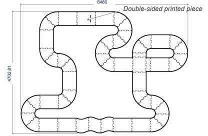
Figure 1- Example circuit of the competition
In addition, the circuits are composed of patterns that the camera must recognize:
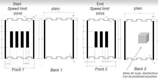
Figure 2- Circuit Reasons
Patterns to delimit speed zones, objects and the end of the circuit can be placed on the different circuits.
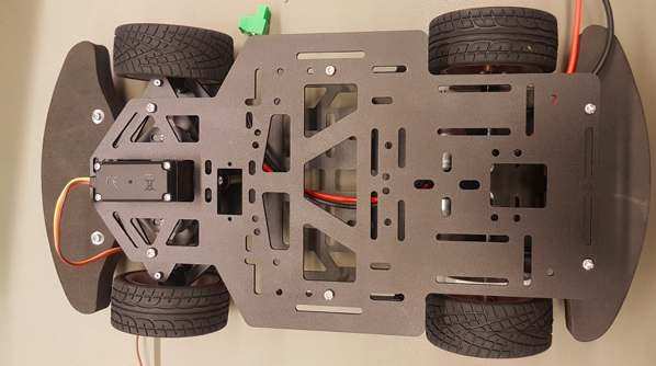
For this challenge we decided to order the new kit made available for this competition consisting of the chassis and the propulsion and steering motors.
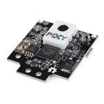
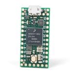
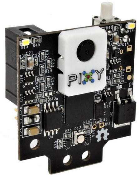
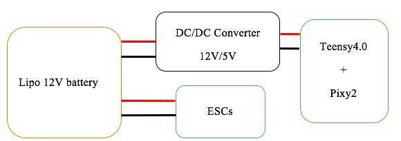
Similarly, we decided to use the pixy2 camera recommended by the NXP. On the other hand, for the software part we chose to use the Teensy4.0 card, which is largely powerful enough in computing speed to steer the car and easy programming using the Arduino IDE. To power everything, we use a Lipo battery (3 cells) or 12V.
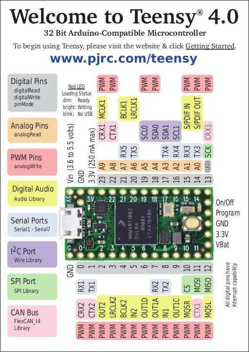
The Teensy4.0 programming board works in 5V while the motors operate in a voltage range from 7V to 12V. To adapt this voltage difference we decided to use a DC/DC converter from 12V to 5V. We could then power the motors and the programming board with the same battery.
In order to operate the steering and propulsion motors of the car from the Teensy4.0 board, we develop two programs one for steering and one for propulsion:
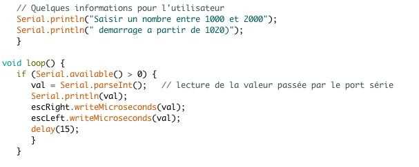
Figure 3- Propulsion Test Schedule
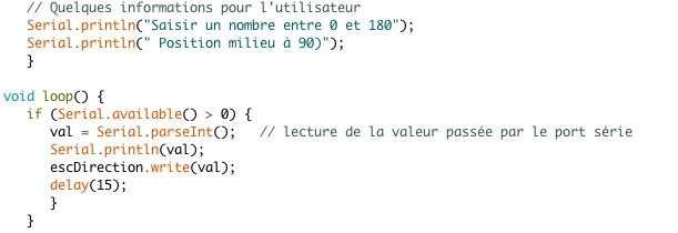
Figure 4- Steer Test Program
However, to be able to operate the propulsion engines we need to initialize the ESC using the BlHeli suite software. The ESC boards are the intermediate boards between the motors and the programming board that drives the motors by sending a PWM signal, which is the control of the speed of the motors according to the value sent by the Teensy4.0 board.
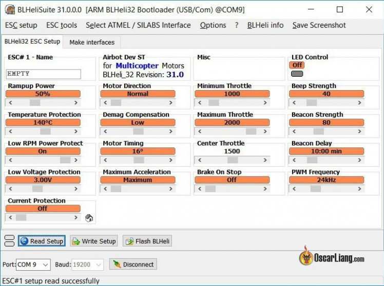
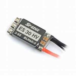
Figure 5- ESC Configuration Software
2.3 HOW THE PIXY2 CAMERA WORKS
The Pixy2 camera has several operating modes, mainly two of which interest us:
- The recognition of forms that would allow us to recognize motives on the circuit.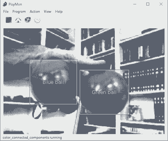
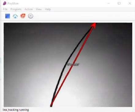
- The recognition of lines in the form of vectors, the camera returns us the coordinates of all the vectors it perceives.
However, the major problem is that you cannot use both modes of operation at the same time. So we only use line recognition to steer the car.
To program this car autonomously using the camera, we manipulate the coordinates of the line vectors around the car and depending on the readings we refocus the car so that it is always in the middle of the track. In addition, when detecting a turn we decrease the speed of the car in order to cross the turn without leaving the circuit.
As the camera sends us about ten readings per second, we also perform a averaging on it in order to guarantee a certain precision on the trajectory error to be corrected.
Thus, according to the values of the coordinates obtained by the camera we actuate the servomotor to turn right or left and different speed levels of the motors depending on the error to be corrected.
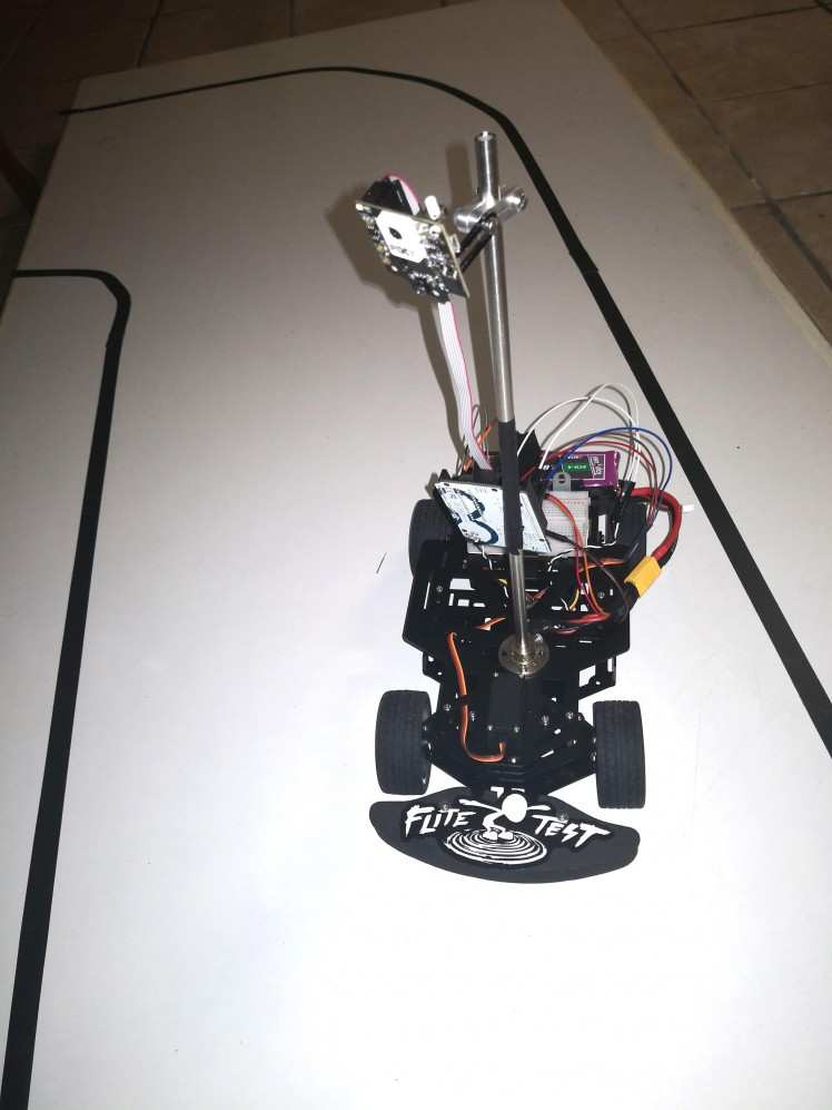
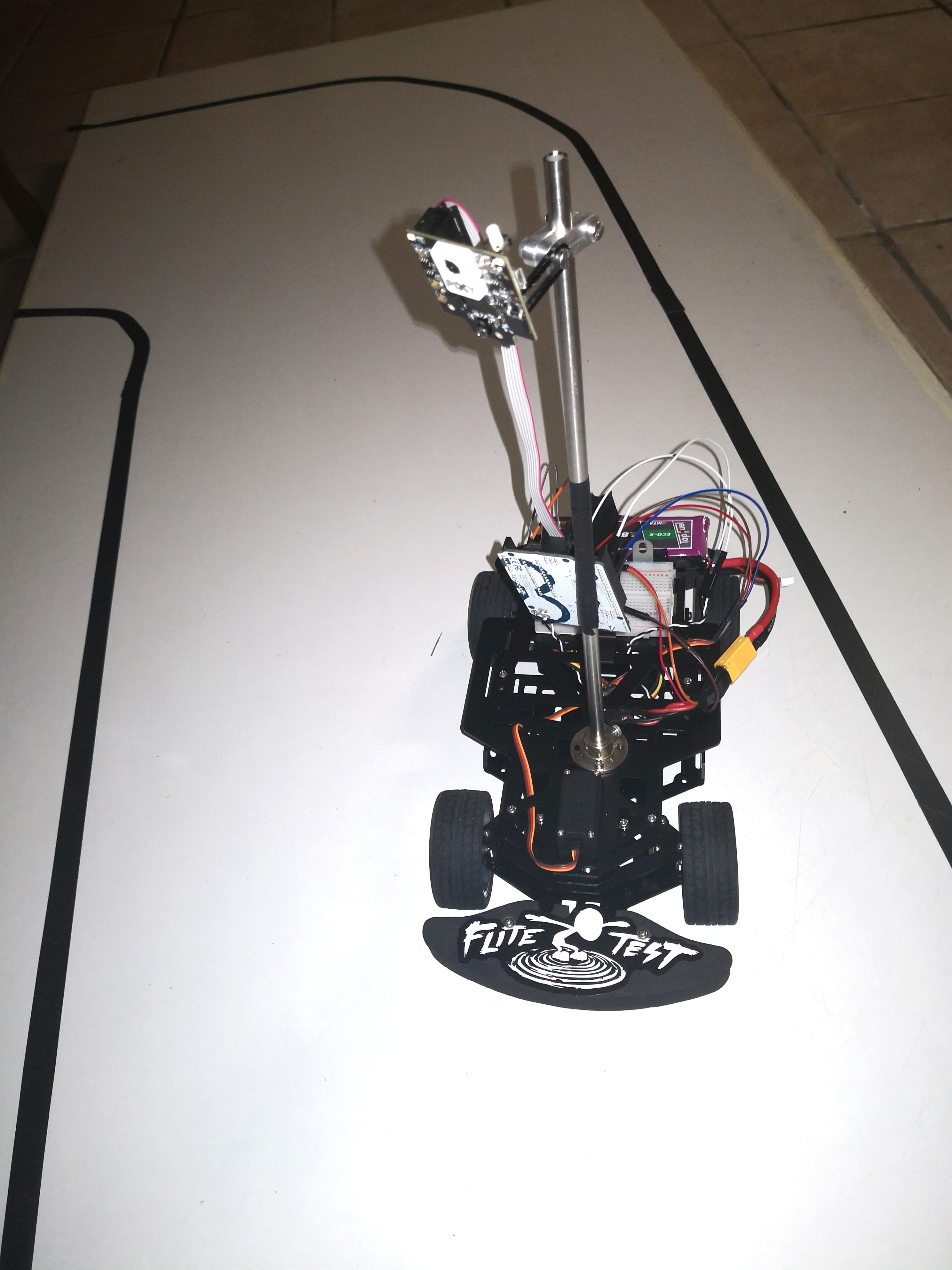
Figure 6- Car during initial solution
After a battery of tests, we realized several problems of this method of tracking trajectory:
-The camera can see a multitude of vectors in real time that it randomly numbers, so it is difficult to recognize the vectors desired or not.
- Recognition of circuit patterns is not easy when using the camera vector mode.
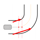
- The major problem is the field of view of the camera. Indeed, during special turns or with strong curvature the camera makes readings of coordinates not usable. As here, it is difficult to correct at the program level so that the car does not cross the limits of the circuit.
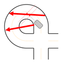
The only possible solution to this problem would be to tilt the camera as much as possible so that it does not see a full turn, only the camera’s shooting width for a maximum allowable height is not sufficient to see the two circuit lines.
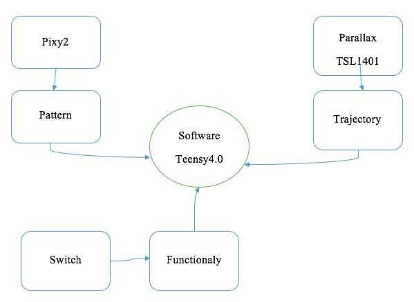
To solve the problems of the Pixy2 camera we thought to add a second camera. We then share the work of autonomy of the car following two cameras:
- The Pixy2 camera in form recognition mode. Knowing the shapes beforehand, this camera will allow us to accelerate, stop or even circumvent an object.
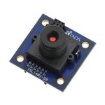
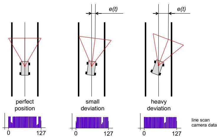
- The Parallax TSL1401 linear camera is a 1D camera that allows viewing over a larger width (often 128 pixels). It returns an intensity value per pixel, that is, it differentiates the contrast between a black line and a white background. Thus, we will correct the trajectory error of the car according to the return of the linear camera as below.
4.2 IMPROVED LINE CAMERA DATA CAPTURE
However, the linear camera has a big defect, the intensity values are disturbed by the change of the lighting during the race, since the calibration of the environmental lighting is done at the beginning of the race.
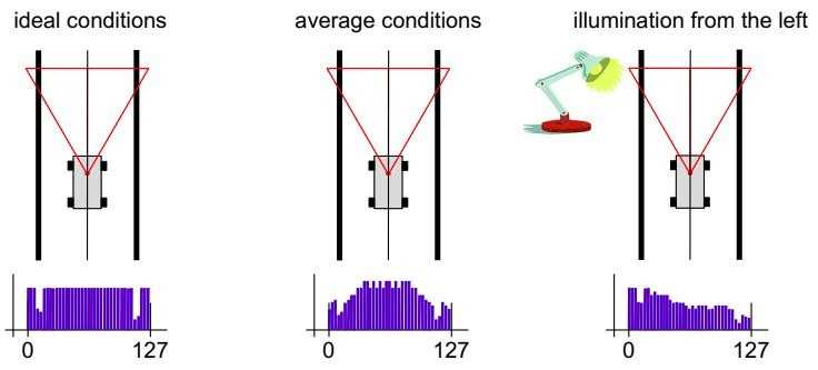
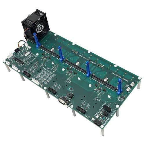
To help against this problem we decided to design a bench of led led directed on the circuit with Kicad, which will allow a constant homogenization of the lighting throughout the race.
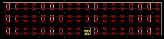
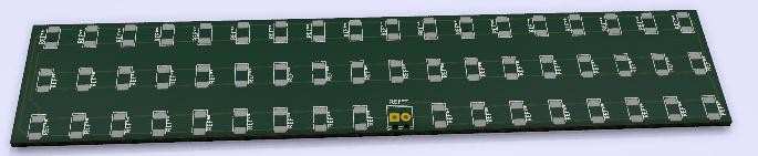
Figure 7- Test Bench PCB
4.3 FIXING OF CAMERAS AND LED BENCH
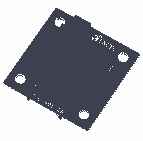
To be able to fix the cameras and the test bench, we decided to make a part with a 3D printer and FreeCAD. This part allows its attachment to the mast of the car and a hook on which will rest the cameras and the test bench. In addition, a tilt system will allow us to manually adjust the tilt desired for the cameras and the led bench. This inclination is one of the most important points for the proper functioning of our system.
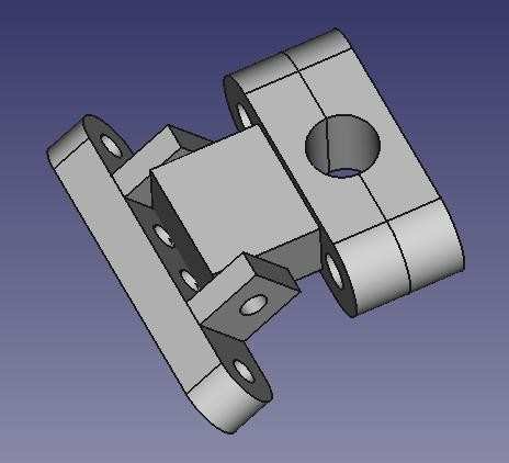
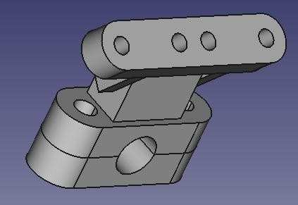
Figure 8- Camera attachment and LED bench
4.4 POWER AND SIGNAL ADAPTER BOARD
To industrialize our system, we designed a printed circuit board composed of the DC/DC converter, the Teensy4.0 board, buttons and terminal blocks. The terminal blocks allow us to wiring different signals and motors. The buttons that have been added will be very useful to the structure of the program, so we can activate the features of our car like different speed regimes or the use of one or both cameras. Then, we created a clean and disconnectable system, which makes it easier to change parts or solve problems.
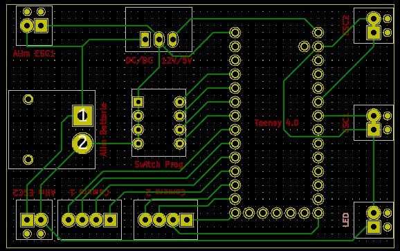
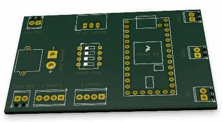
Figure 9- Signal Adaptation Board PCB
4.5 IMPROVEMENT OF THE SOFTWARE PART
Note: following the COVID-19 containment, we have not yet completed this part.
We might think that the software part would be more difficult to develop but it is quite the opposite. However, it takes longer to achieve, it is easier because we separate the lenses with several devices as with the two cameras.
In addition to calculating the trajectory error of the car, we aim to add to the trajectory control a Proportional Derived corrector:

This will allow to be faster on the correction of the trajectory of the car.
During this project we realized an autonomous car allowing to follow a circuit and to manage itself when turning or presence of object.
We could add some sensors such as ultrasonic obstacle sensors and speed sensors on the wheels to optimize the speed of our car around the circuit.
CAD, enclosures and custom parts
Code
Credits
Related products


Leave your feedback...