





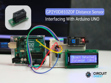
Arduino Proximity Alert Using Gp2y0d80z0f Sensor

Made by electroscope_archive / Artificial intelligence / Robotics / Sensors
About the project
Build a fast, digital 10 cm proximity detector using the Sharp GP2Y0D80Z0F sensor, Arduino Uno, and an I2C LCD — perfect for robotics.
Project info
Items used in this project
Hardware components


Story
In this beginner-friendly project, you’ll learn how to interface the GP2Y0D80Z0F distance sensor with Arduino Unoto detect objects within ~10 cm and display status on a 16×2 I2C LCD and Serial Monitor. This is perfect for basic obstacle detection, presence sensing, or safety triggers.
GP2Y0D80Z0F Distance Sensor with Arduino Uno
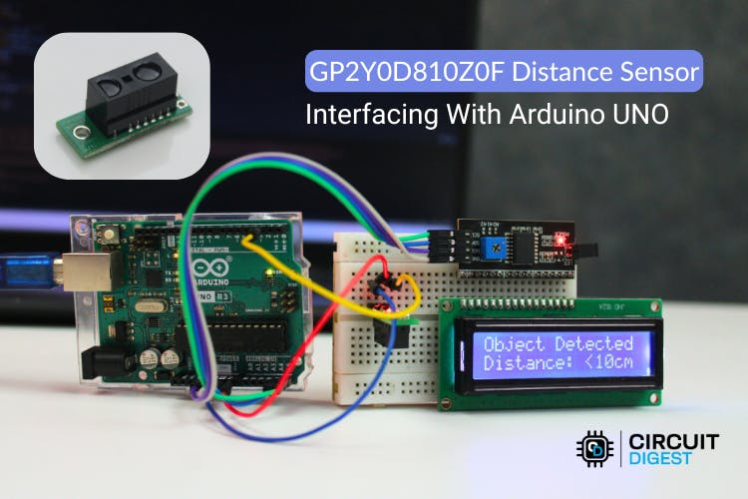
GP2Y0D80Z0F Distance Sensor with Arduino Uno
What You’ll BuildYou’ll wire the GP2Y0D80Z0F sensor to an Arduino, read its digital output to determine whether an object is detected in front of it, and then show real-time status on both the LCD and serial output.
Components
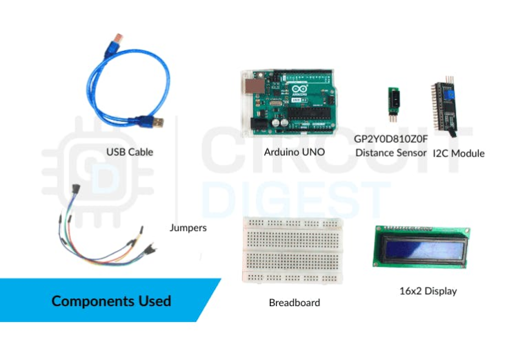
Components
How the Sensor WorksThe GP2Y0D80Z0F uses infrared to detect nearby objects:• When an object is within ~10 cm, the sensor output goes LOW.• When no object is detected, the output stays HIGH.
This digital signal makes it very easy to use with Arduino — no complex voltage mapping or analog interpretation is needed.
Wiring GuideConnect your components like this:
GP2Y0D80Z0F → Arduino Uno
GND → GND
- GND → GND
VIN → 5V
- VIN → 5V
OUT → Digital Pin 2
- OUT → Digital Pin 2
I2C LCD → Arduino Uno
GND → GND
- GND → GND
VCC → 5V
- VCC → 5V
SDA → A4
- SDA → A4
SCL → A5
- SCL → A5
Wiring Diagram
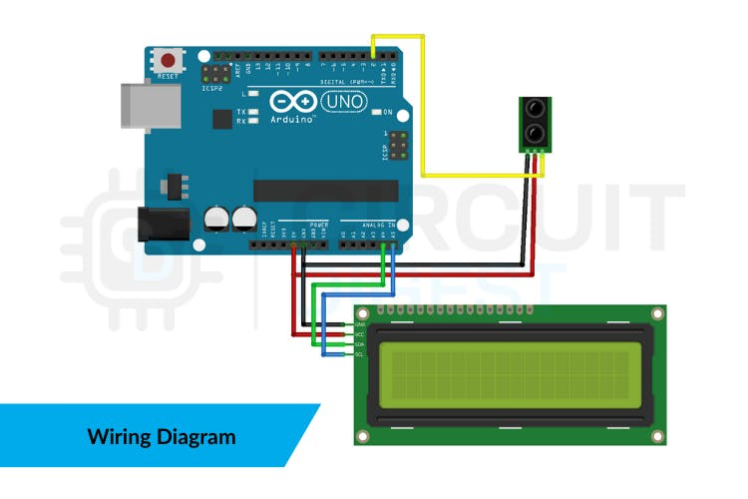
Wiring Diagram
Tip: Use consistent wire colors (e.g., black for GND, red for 5V) to make your build easy to follow.
Tip: Use consistent wire colors (e.g., black for GND, red for 5V) to make your build easy to follow.Arduino Sketch
This sketch reads the sensor and updates both the LCD and Serial Monitor:
#include <Wire.h>
#include <LiquidCrystal_I2C.h>

// GP2Y0D80Z0F sensor output pin
const int SENSOR_PIN = 2;

// Initialize LCD (I2C address 0x27, 16×2)
LiquidCrystal_I2C lcd(0x27, 16, 2);

void setup() {
  Serial.begin(9600);
  pinMode(SENSOR_PIN, INPUT);

  lcd.begin();
  lcd.backlight();

  lcd.setCursor(0, 0);
  lcd.print("Proximity Sensor");
  lcd.setCursor(0, 1);
  lcd.print("Initializing...");
  delay(2000);
  lcd.clear();
}

void loop() {
  int state = digitalRead(SENSOR_PIN);

  lcd.clear();
  if (state == LOW) {
    lcd.setCursor(0, 0);
    lcd.print("Object Detected");
    lcd.setCursor(0, 1);
    lcd.print("Distance < 10cm");
    Serial.println("Status: Object detected (<10cm)");
  } else {
    lcd.setCursor(0, 0);
    lcd.print("No Object");
    lcd.setCursor(0, 1);
    lcd.print("Distance > 10cm");
    Serial.println("Status: No object (>10cm)");
  }
  delay(200);
}
The sensor continuously sends an infrared signal and monitors reflections.
- The sensor continuously sends an infrared signal and monitors reflections.
When a reflective object is close, the output goes LOW, which the Arduino reads as “detected.”
- When a reflective object is close, the output goes LOW, which the Arduino reads as “detected.”
The sketch updates the display with clear text and prints status to the Serial Monitor for debugging.
- The sketch updates the display with clear text and prints status to the Serial Monitor for debugging.
Hardware Set up
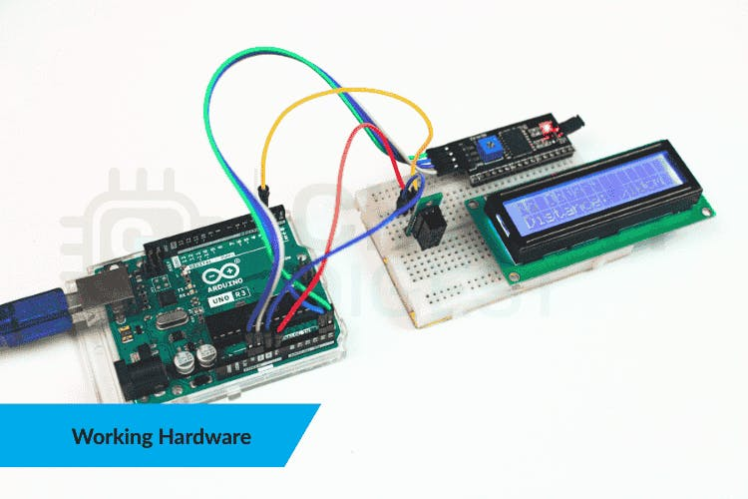
Hardware Set up
Practical Applications✔ Obstacle detection for small robots✔ Touchless presence switches✔ Simple automation triggers✔ Safety proximity alerts
Troubleshooting TipsHere are a few common issues and fixes:• Blank LCD: Check I2C address (try 0x27 or 0x3F).• Incorrect readings: Verify wiring — loose grounds and sensor output wiring can cause false detections.• Flickering display: Update the screen only when the sensor state changes.
Project Wrap-UpThis quick Arduino projects shows how easy it is to add digital proximity sensing to your build with the GP2Y0D80Z0F. Whether you’re starting with sensor interfacing or making interactive installations, this setup gives you reliable detection and a clean user interface.
Working Video
Schematics, diagrams and documents
Code
Credits
Related products





Leave your feedback...